• One 24v power supply with power leads
• One 12” or 17” UVC Lamp
• Two lamp mounting screws
• One light shield
• One lamp lead
• Six self tapping screws
• One lamp mounting gasket
• Two wire nuts
• Viewport
• One lamp mounting plate
• UVC warning label
• Replacement lamp log sheet
• Viewport label
• Warranty card
6 power cord (some models)
Package Contents:
Safety Precautions:
It is recommended that this unit be installed and maintained by a trained technician.
WARNING: UV Hazard. Always protect eyes from ultraviolet light. NEVER look at UV
lamps in operation. Unplug or disconnect power before re-lamping or servicing.
WARNING: Severe eye damage or temporary blindness may occur.
WARNING: DO NOT operate outside of air handler. Mount product in preferred
location rst.
WARNING: No openings should be allowed which would give direct line-of-sight to the
UV light.
In the event of accidental breakage or replacement of the ultraviolet lamp, please ensure
that the lamp is disposed of in accordance with local and state environmental laws re-
garding uorescent lamps containing mercury.
Notice:
All wiring inside of the air handler in direct line of site of the UV lamp must be shielded
with aluminum foil tape or equivalent non-combustible material. When installing this
unit, select a mounting location that prevents ultraviolet light exposure to synthetic or
other plastic components with unknown resistance to ultraviolet light. Ultraviolet light
may cause color shi or structural degradation of plastic internal components.
Second Lamp Option:
Installation :
1. Determine a suitable location to install unit housing. Mounting location should be of sucient
strength as to support the unit, otherwise reinforcement of the duct work may be necessary. Fasten
the unit in place with two self-tapping screws (supplied). if mounting internally mount in the elec-
tronics section of the AHU , do not mount the power supply inside the air stream duct.
2. Select location for UV lamp module. for external installation Drill a 1” hole. Mount mount-
ing plate over drilled hole with four self-tapping screws (supplied). Insert UV lamp module into
in hole. Attach to HVAC system with two self-tapping screws (supplied). To utilize the internal
mounting bracket, rst install the bracket inside the air handler in a location that will position
the UV lamp such that it bathes the entire surface to be treated. Plug the lamp connector onto the
lamp, (and snap into the bracket internal mounting).
e rectangle pin pattern allows connection in two positions.
3. Connect power wires to the secondary (24VAC) of a UL Listed Class 2 dedicated transformer
(minimum 40VA) with the primary of the transformer connected to the appropriate voltage (see
transformer instructions). is should be done in accordance with all state and local electrical
and building codes.
Ultravation supplies two types of power supplies. Both power supplies have identical features and
output strength. the dierence is in the incoming power connection. One style is 2 input wires that
will connect directly to the 24 VAC transformer. e other type is a 6 foot cable that connects to
the power supply and plugs into the power supply.
Disclaimer: e health aspects associated with the use of this product and its ability to aid
in disinfection of environmental air have not been investigated by UL.
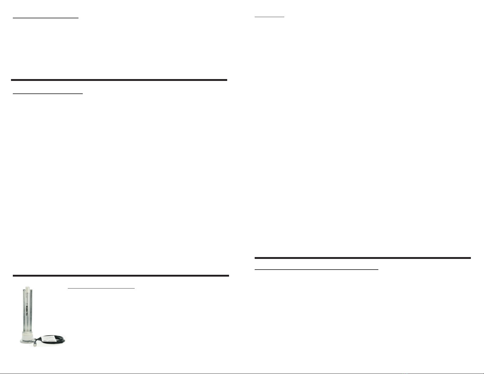
Some HVAC equipment can benet from additional UV lamps.
e Ultravation EZUV power supply will operate a second
UV lamp to disinfect additional areas inside the HVAC system
such as the blower fan. e EZ-Light 6P is designed specically
for second lamp applications or add odor control capabilities.
See literature included for details of all available
upgrades.
Installation steps for UV viewport:
1. Find a location on the air handler or duct work that will be visible and be in direct line
of sight of UVC light.
2. Ax UV viewport label to air handler or duct work.
3. Drill a 3/8’’ hole through the label and air handler or duct work in marked location on
label.
4. Press in UV viewport until it snaps into place.


