Ulvac G-Tran Series User manual

Y005-0931-EI-003-13
G-TRAN Series
Pirani Vacuum Gauge Sensor Unit
SW1-1 Standard Type
SW1-2 Serial Communication Type
Instruction Manual
This manual is for the sensor units of the
following serial numbers:
Serial Nos. 00001 and higher.
Read this manual before operation and keep
it at hand for immediate reference.
Components Division,
ULVAC, Inc.


i
Prior to Operation
Upon receipt of this detector, make sure that it is the correct model you ordered and that it is not damaged
in transit.
Read this instruction manual before installing, operating, inspecting, or
maintaining the product and fully understand the safety precautions,
specifications and operating procedures regarding the product.
The copyright of this instruction manual is held by ULVAC, Inc.
You are prohibited from copying any portion of this instruction manual without
the consent of ULVAC Inc.
You are also prohibited from disclosing or transferring this instruction manual
to third parties without the express written consent of ULVAC Inc.
The contents described in this instruction manual are subject to change without
prior notice because of changes in specifications or because of product
improvements.
Safety Notations
Safety symbols are used throughout this instruction manual to call the operator's
attention to safety. The terminology used in safety symbols is classified below.
Indicate status of urgency of danger when failure to comply with DANGER
results in serious personal injury or death
The work ignoring this warning will lead to serious damage to human life or
factory facility (including this equipment) at a high probability.
Indicate status of danger when failure to comply with WARNING results in
serious worker’s injury or death.
The work ignoring this warning will cause possibility leading to serious damage
to human life or factory facility (including this equipment)
Indicate status of danger when failure to comply with WARNING results in
minor injury or moderate damage.
The work ignoring this warning will cause possibility leading to minor damage
to worker or breakage to equipment or necessary to adjust.
Direct hazard is not existed, describe the necessity to know
from the viewpoint of worker’s safety or correct and safe operation of
equipment
✔Note

ii
Safety Precautions
For safe operation of this unit, read this manual and the following safety precautions.
Servicing
For repair and servicing, contact your local ULVAC representative or
Components Division, ULVAC, Inc., Japan.
Turn OFF power.
If the unit fails, immediately turn OFF the power.
Use of a failed unit may cause a fire or electric shock.
Turn OFF power.
If the unit gets unusually hot or gives off smoke or unusual smell, immediately
turn OFF the power. Otherwise, fire can result.
Line voltage
Before turning on the power to this unit
, make sure that the operating voltage
and supply power are in agreement. If incorrect power is connected, this unit and
devices connected to this unit may fail or fire may result. The over-voltage
comes under Category 1.
Power source
The unit may only be connected to supply and measurement units that confirm
to the requirement to the requirements of a grounded protective extra-low voltage
(SELV-E according to EN 61010). The connection to the unit has to be fused.
Protective grounding
Always connect this unit
to a grounded vacuum chamber. Use a conductive
metal clamp for the KF flange. If it is not correctly grounded, instrument will not
only indicate a correct pressure, but also lead to damage to connected devices or
fire.
When isolated with the vacuum chamber, ground the case section (D-sub
connector shell section) with a class D (class 3) ground.
Check connection
See to it that the cable connected to each pin is not in contact with other pin and
the case. Also do not mistake pin assignment. Incorrect connection may cause
failure or fire of this unit or device connected to this unit.
Over-pressure of vacuum chamber
Do not connect the instrument to a chamber where the pressure in the sensor
head is higher than atmospheric pressure. If the pressure in the sensor head
exceeds atmospheric pressure, the sensor head may be broken and may pop out
from the connection, causing harm to the surrounding, including humans. If the
pressure exceeds atmospheric pressure, install a separation valve so that the
pressure in the sensor head does not exceed atmospheric pressure.
Relativity property on gas type
The pressure value and
sensitivity of this unit varies by the types of gases
exposed to. The sensitivity values on this document are based on Nitrogen gas
application, therefore please be aware of excess pressure for other gas
applications.
Do not disassemble.
Do not disassemble this unit. Fire or electric shock can result. If it is modified,
its actions are out of warranty.
Do not modify.
Do not modify the instrument. If it is modified, fire or electric shock can result
and its actions are not warranted.
Turning on power
Before turning on the power to this unit
, connect the sensor head, display,
evaluation unit, cables and others. Otherwise, this unit and devices connected to
it may be damaged or fire can result. Also the filament may break.

iii
Operating environment
Use this unit within the scope of the environment set forth in the specifications.
Operating environment
Do not use this unit in a place where it may be splashed with water or where
temperature is so high that dew may condense. If water is admitted into this unit,
failure and electric leak or fire can result.
Keep out foreign object
Keep the instrument free from metal, combustibles and other foreign objects,
which may be admitted into the instrument through the opening
Ensure ventilation
Do not set the instrument in a sealed container, but set it where ventilation is
ensured. If it is set in a sealed container, electronic parts will be heated, resulting
in short life.
Operating environment
If the instrument is exposed to active gas chemically (halogen gas, halogen
system gas, etc), the filament may burn out or pressure characteristics may
change. If the instrument is to be used in such an environment, provide an
isolation valve between the instrument and vacuum chamber and
seal the
isolation valve so that the instrument is not exposed to the gas.
Operating environment
If the instrument is exposed to the oil mist from rotary pump or depositing gas
or CVD raw material gas, the filament may burn out or pressure characteristics
may change. If the instrument is to be used in such an environment, provide an
isolation valve between the instrument and vacuum chamber and seal the
isolation valve so that the instrument is not exposed to the gas.
Moisture and fouling
If there is
a large quantity of fouling in the gauge head from the gradual
vaporization of moisture or organic matter, the ZERO point-
side pressure
accuracy and response speed will be affected. Review installation locations and
methods so that fouling does not occur.
Pressure reading check
Immediately after use, check the pressure readings, especially the pressure for
the atmospheric pressure-side and ZERO point-side. Adjust the atmospheric
pressure and ZERO point as necessary.
The pressure reading is affected by the environmental temperature due to the
principle of the Pirani gauge. The atmospheric pressure and ZERO point
adjustments may also deviate because of vibrations during transport.
Magnetic field influence
The atmospheric pressure-side pressure reading
of the sensor is particularly
affected (about 10%) by the influence of magnetic fields of 0.01 T (100 G). If the
sensor is affected by magnetic fields, install a magnetic shield.
Temperature fluctuations
The ambient temperature of the gauge head affects the measured value due to
the principle of the Pirani gauge. If the ambient temperature dramatically
deviates from the temperature during calibration (approx. 25°C), adjust the
atmospheric pressure and ZERO point.
Contact capacity
Use a capacity for externally installed contacts greater than the input power
supply voltage and 30 VDC or higher.
Contact leak current
Be aware of contact leak current. If a current of 0.1mA or higher flows between
the input signal pin to the GND terminal, that may be treated as signal input.
Laying cables
When laying transmission lines for communication, see to it that they are not in
the proximity of , or parallel to, power lines, high voltage lines, high frequency
lines, etc. Otherwise, malfunction can result.

iv
Remote host
Use the isolation type remote host that is highly immune to noise for PC and
PLC.
Impact
Do not give an impact to this unit. It can be a cause of filament breakage or leak
of the gauge head or damage of the fixing screw.
Leak test
Perform a leak test when the gauge head is replaced or removed. There is a
possibility of leaking from impacts to the pin section.
Packing for transit
If the instrument is to be transported, restore it to the condition before it was
shipped from the ULVAC plant. If it is transported bare or as installed in a
system, it may be damaged.
Maintenance
Aluminum electrolytic capacitor is used in the electric circuit of this unit. The
life of the aluminum electrolytic capacitor becomes shorter with increase of the
ambient temperature, To prevent devices from being damaged, it is
recommended to conduct maintenance about once every 3 years.
Discarding
If this unit
is discarded, follow the regulations of your local government. If the
sensor head was used in an environment that can cause danger to human body,
dispose of it through a specialized refuse disposal agency. Incidentally, expenses
for discarding the instrument are on the user’s account.

v
Revision History
Date
No.
Reason
Aug. 24, 2009
04
First edition S/N:00001~
Aug. 24, 2009
05
Added “EC Declaration of Conformity (Chapter 14)”
Apr. 1, 2011
06
Added “China RoHS (Chapter 13)”
Oct. 6, 2011
07
Correction of errors
May 21, 2013
08
Added manual(CD) and Quick manual (Section 1.2)
July 7, 2014
09
Correction of errors
Oct. 20, 2014
10
The color of Power LED changes from green to blue.
Added “bakeout 150
°
C (without electronics unit) (Section 1.1)”
Apr. 15, 2015
11
Added sensor head SWP-R1/8
Added Fig.11.3 (Section 11.1)
Apr. 20, 2016
12
Correction of errors
Nov. 21, 2017
13
Added “Output pressure range (Section 1.1)”
Added “measurement unit conversion factor (Section 5.1.1)”

vi
Contents
Page
Prior to Operation.............................................................................................................................................i
Safety Notations...............................................................................................................................................i
Safety Precautions...........................................................................................................................................ii
Revision History.............................................................................................................................................. v
Contents ........................................................................................................................................................vi
1. Specifications ..................................................................................................................................1
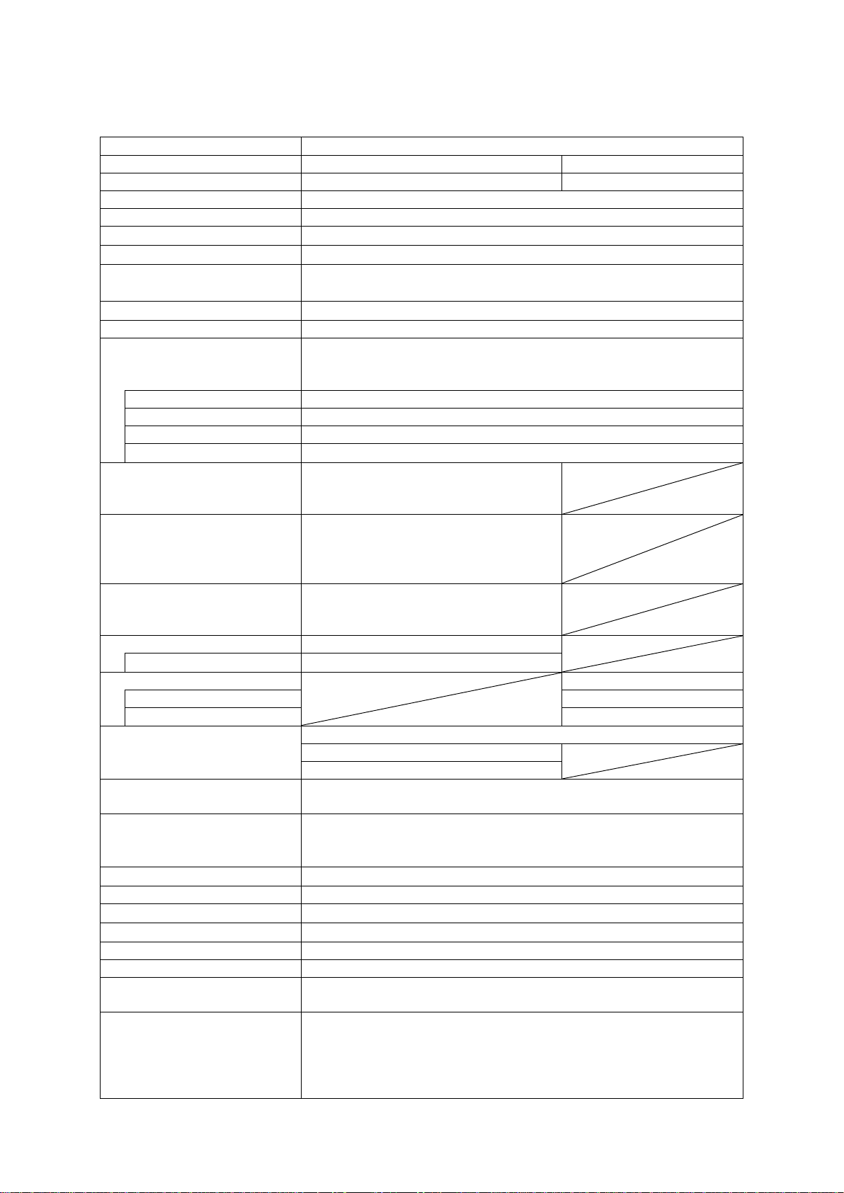
1.1. Standard Specifications...................................................................................................................1
1.2. Unpacking and quantity check ........................................................................................................2
1.3. Option..............................................................................................................................................2
1.4. Dimensional Drawings....................................................................................................................3
1.4.1. SW1-1/SW1-2 Dimensional Drawings.................................................................................3
1.4.2. SWP-16 Dimensional Drawings...........................................................................................4
1.5. Unpacking and Quantity Check ......................................................................................................4
2. Cautions in Operation......................................................................................................................5
2.1. Checks immediately after operation................................................................................................5
2.2. Cautions on Operating Environment...............................................................................................5
2.3. Cautions in Operation......................................................................................................................6
2.4. Installing the Instrument..................................................................................................................6
2.4.1. Sensor installing environment ..............................................................................................6
2.4.2. Installing the sensor head......................................................................................................7
3. Names of Components and Description of Functions..................................................................... 8
3.1. Controller Unit ................................................................................................................................8
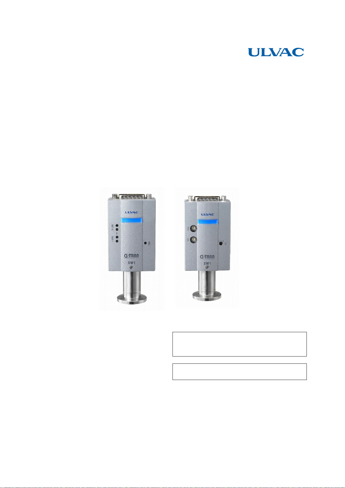
3.2. Front Panel Standard Type SW1-1............................................................................................9
3.3. Front Panel Serial Communication type SW1-2...........................................................................10
3.4. Input / Output Connector Standard type SW1-1 ........................................................................11
3.5. Input/Output Connector Serial Communication type SW1-2.....................................................12
4. Circuit in the power supply........................................................................................................... 13
5. Signals...........................................................................................................................................14
5.1. Pressure Signal Output (SW1-1 and SW1-2)................................................................................14
5.1.1. Pressure converting equation..............................................................................................14
5.1.2. Output of measurement value in each state ........................................................................14
5.2. I/O Signal Output (Standard Type SW1-1 only)...........................................................................15
5.2.1. Sensor error signal (Standard Type SW1-1 only)...............................................................15
5.2.2. Setpoint actuating signal (Standard Type SW1-1 only)......................................................15
5.3. I/O Input Signal (Standard Type SW1-1 only)..............................................................................16
6. Setting the Setpoint (Standard Type SW1-1 only)........................................................................17
6.1. Set point ON/OFF pressure...........................................................................................................17
6.2. Wiring in setting Setpoint..............................................................................................................17
6.3. Setting of Setpoint.........................................................................................................................18
7. How to use Serial Communication (Serial communication type SW1-2 only).............................19
7.1. Communication Specifications......................................................................................................19
7.2. Various Settings ............................................................................................................................19
7.2.1. Connection diagram............................................................................................................19
7.2.2. Baud rate setting.................................................................................................................20
7.2.3. Address setting....................................................................................................................20
7.3. Standard Data Format....................................................................................................................21
7.3.1. List of commands ...............................................................................................................21

vii
7.3.2. When receiving is normal...................................................................................................21
7.3.3. When receipt is not normal.................................................................................................21
7.4. Command ......................................................................................................................................22
7.4.1. Reading the measurement value/status...............................................................................22
7.4.2. Zero point adjustment command ........................................................................................22
7.4.3. Atmospheric pressure adjustment command ......................................................................22
7.4.4. Zero point and atmospheric pressure adjustment clear command......................................22
7.4.5. Status reading......................................................................................................................22
7.4.6. Reading software version....................................................................................................22
7.4.7. Reading setpoint 1 set value ...............................................................................................23
7.4.8. Reading the setpoint 2 set value .........................................................................................23
7.4.9. Writing the setpoint 1 set value ..........................................................................................23
7.4.10. Writing the setpoint 2 set value ..........................................................................................23
7.5. Checksum......................................................................................................................................24
7.6. Status.............................................................................................................................................25
7.6.1. SH (Higher case of status)..................................................................................................25
7.6.2. SL (Lower case of status) ...................................................................................................25
7.7. ASCII Code Table.........................................................................................................................26
8. Zero Point Adjustment and Atmospheric Pressure Adjustment.................................................... 27
8.1. Checking the Completion of Adjustment......................................................................................27
8.2. Adjusting Method..........................................................................................................................27
8.3. Zero Point, ATM Adjustment, adjustment resetting .....................................................................28
8.4. Zero Point Adjustment ..................................................................................................................28
8.5. Atmospheric Pressure Adjustment................................................................................................28
8.6. Resetting........................................................................................................................................28
8.7. Memory Function..........................................................................................................................28
9. Replacement of Sensor Head ........................................................................................................29
9.1. Tool...............................................................................................................................................29
9.2. Removing the Sensor Head...........................................................................................................29
9.3. Installing the Sensor Head.............................................................................................................30
9.4. Leak test ........................................................................................................................................30
9.5. Adjustment after Replacement of Sensor Head.............................................................................30
10. Troubleshooting ............................................................................................................................31
10.1. Troubleshooting.......................................................................................................................31
10.2. Checking the Filament and Temperature Sensor for Burnout..................................................34
10.3. Insulation between Sensor Head Pin and Case ........................................................................34
11. Technical Data...............................................................................................................................35
11.1. Dependence on Gas Specie......................................................................................................35
11.2. Zero Point Adjustment and Atmospheric Pressure Adjustment...............................................36
11.3. Scheduled Adjustment .............................................................................................................36
12. Warranty........................................................................................................................................ 37
13. China RoHS Declaration...............................................................................................................38
14. EC Declaration of Conformity......................................................................................................39
15. Certificate of decontamination......................................................................................................40

1
1. Specifications
1.1. Standard Specifications
Name
Pirani vacuum gauge
Type
Standard type
Serial communication type
Model name
SW1-1
SW1-2
Compatible sensor head
1 pc.
Applicable sensor head
SWP-16, SWP-R1/8
Measurable pressure range
5.0 ×10⁻² to 1.0 ×10+5 Pa
Output pressure range
1.0 ×10⁻² to 1..2 ×10+5 Pa
Measurement accuracy *1
(N2)
±10% from 1 ×10⁻¹ Pa to 1 ×10+4 Pa
±20% from 1 ×10
+4
Pa to 1 ×10
+5
Pa, 5 ×10
-2
Pa to 1 ×10
-1
Pa
Repeatability
±2% from 1 ×10⁻¹ Pa to 1 ×10+4 Pa
Sampling time
50 ms 5 times of moving average processing
Measurement value output
Output voltage 0 to 10 VDC
Output indication 1.7 V to 8.0 V ( Output pressure range 1.0V to 8.1V)
Log output 1 V/div
Update time
50 ms
Resolution
4 mV
Output error
±3 mV
Output impedance
10 Ω
Adjustment
ADJ: one switch
Zero point adjustment, atmospheric
pressure adjustment, adjustment reset
Control input signal
Zero point adjustment, atmospheric
pressure adjustment, adjustment reset
Actuated with open collector input,
negative logic
Control output signal
Sensor error signal, setpoint 1/2
Open collector output, negative logic
Rating: 30 VMAX, 50 mAMAX, 70 mW
Monitor for setpoint
Setpoint 1/2: 0 to 10 VDC LOG output
Output impedance
10 Ω
Serial communication
RS-485/RS-232C
Baud rate
9600/19200/38400 bps
Memory function
Backed up with EEPROM
LED display
POWER/ERROR: Power error LED
SET1: Setpoint 1 LED
SET2: Setpoint 2 LED
Sensor head material
Filament: Pt
Others : SUS304, FeNiCo, Ni, Au, glass, ceramic
Sensor head pressure max
2 ×10+5 Pa (absolute)
The breakdown pressure of the flange and clamp are to be considered
otherwise.
Operating temperature range
10°C to 40 °C
Operating humidity range
15% to 80% (not condensing)
Storage
-20 to 65 °C
Bakeout
150°C (without electronics unit)
Mounting position
Free
IP protection class
IP30
Line voltage
18 V to 30 VDC (ripple, noise <1%)
2 watts(4.8 watts when power is turned on)
CE standard
Low voltage directive EN61010-1:2001(2nd Edition)
Radiation field intensity measurement:
EN55011:2007, A2:2007 group1 ClassA (Radiated)
Radiation electromagnetic field test: EN61000-4-3:2006
Static electricity test: EN61000-4-2:1995, A1:1998,A2:2001

2
Transient burst test: EN61000-4-4:2004
Lightening surge test: EN61000-4-5:2006
Conduction test: EN61000-4-6:2007
Commercial magnetic field test: EN61000-4-8:1993, A1:2001
Over-voltage category
Category I: Connected to a circuit that holds down transient
over-voltage at a sufficiently low level
Input/output connector
D-sub15 pin Connector ( male, 2.6 mm screw)
Sensor head inner volume
Approx. 7.3 cm3(SWP-16)
Basic unit weight
Controller approx. 105 g, sensor head (SWP-16) approx. 45 kg
Outside dimensions
70 ×46 ×28 (controller unit)
*1: The accuracy after atmospheric pressure and ZERO point adjustment. Please carry out atmospheric
pressure and ZERO point adjustment before use especially. Moreover, since calibration gas is N2,
when other gas is measured, be careful of an error of measurement.
1.2. Unpacking and quantity check
Instruction manuals
(CD)
1
Quick manual
(Paper)
1
1.3. Option
Display unit
1CH Digital
ISG1 (24VDC power supply type)
4CH Digital
IM1R1(24VDC power supply type)
1M2R1 (100VAC power supply type)
Sensor Head
See Key Specifications "Compatible sensor head" .
Display cable
2 m, 5 m, and 10 m (between measuring unit and display unit)
D-sub 15 Pin Connector (Female, 2.6mm Screw)
JCSS alibration certificate
General proofreading test
Inspection certificate
Calibration certificate

3
1.4. Dimensional Drawings
1.4.1. SW1-1/SW1-2 Dimensional Drawings
30 70
60
(R 50)
(100)
28
46
51
(5)

4
1.4.2. SWP-16 Dimensional Drawings
1.5. Unpacking and Quantity Check
Upon receipt of the instrument, unpack it and check it to see that it is not damaged in transit and that
accessories are supplied as specified.
SW1 Pirani gauge basic unit (with sensor head)
1 pc.
Instruction manual(CD)
1 copy
Quick Manual (paper)
1copy
(45.9)
(39.5)
φ30
NW16
キー溝
(59.9)
(66.3)
SWP-16 SWP-R1/8

5
2. Cautions in Operation
Check the following before starting operation.
2.1. Checks immediately after operation
Relativity property on gas type
The pressure value and sensitivity of this unit varies by the types of gases
exposed to. The sensitivity values on this document are based on Nitrogen gas
application, therefore please be aware of excess pressure
for other gas
applications.
Check pressure indication
Check the pressure indication immediately after operation, particularly the
atmospheric pressure and the zero point pressure. Adjust atmospheric pressure
and zero point as and if necessary. Because
of the operating principle of the
Pirani gauge, the pressure indication is affected by the environment temperature
and others. Also the atmospheric pressure and zero point adjustments may
change because of the vibration during transportation.
2.2. Cautions on Operating Environment
Over-pressure in vacuum chamber
Do not connect the sensor head to a chamber where the pressure in it exceeds
atmospheric pressure. The sensor head may be damaged or may pop out from the
connector, causing damage to the surroundin
g, including human body. If the
pressure in the chamber exceeds atmospheric pressure, provide an isolation valve
so that the pressure in the sensor head does not exceed atmospheric pressure.
Operating environment
Do not use the instrument in a place
where it may be splashed with water or
where humidity is so high as to cause condensation. If water is admitted into the
instrument, failure, power leak or fire can result.
Water and incrustation
The ZERO point pressure sensitivity and reaction speed can be influenced by
presence of water and organic deposition inside sensor head. Please consider the
location or any measure to reduce incrustation upon use.
Operating environment
The filament may break or the pressure characteristics may change if the
instrument is exposed to gas, such as halogen or halogen-
based gas. If the
instrument is used in such an environment, seal the isolation valve during
operation so that the instrument is not exposed to such gases.
Operating environment
If the instrument is exposed to the oil mist from the rotary pump or CVD raw
material gas, the pressure characteristics may change. If the instrument is used in
such an environment, provide an isolation valve and seal it so that the instrument
is not exposed to such type of gas.
Magnetic field influence
The atmospheric pressure-
side pressure reading of the sensor is particularly
affected (about 10%) by the influence of magnetic fields of 0.01 T (100 G). If
the sensor is affected by magnetic fields, install a magnetic shield.
Keep out foreign objects
Protect the instrument so that metals or combustibles are not admitted into the
instrument through the opening
Temperature change
Because of the principle of the Pirani gauge, the measurement value is affected
by the sensor head ambient temperature. If the ambient temperature at the time
of calibration deviates noticeably from calibrating temperature (approx. 25°C),
make zero point adjustment
Operating environment
Use this unit in the environment as set forth in the specifications.

6
Impact
Do not give an impact to this unit. It can be a cause of filament breakage or leak
of the gauge head or damage of the fixing screw.
2.3. Cautions in Operation
Line voltage
Before turning on power, make sure that the operating voltage and the supply
voltage are in agreement. If the instrument is connected to an incorrect power,
not only the instrument fails but also devices connected to this unit
may be
damaged or fire can result. Do not apply a voltage in excess of 30 VDC.
Check connection
See to it that the cable connected to each pin is not in contact with other pin or
case. Also do not mistake the pin assignment. Incorrect connection may damage
this unit or components or may cause fire.
Operating power
Always connect this unit to a power supply or evaluation unit that is compatible
with the EN61010 SELV-
E standard. Also install a fuse in the 24V power
supply.
Turning on power
Before turning on the power to this unit
, connect the sensor head, display,
evaluation unit, cables and others. Otherwise, this unit and devices connected to
it may be damaged or fire can result. Also the filament may break.
• Fix the cable so that undue force is not applied to cable connections.
• Tighten the connector fixing screws securely.
• Start measurement more than 20 minutes after turning on power.
2.4. Installing the Instrument
2.4.1. Sensor installing environment
Protective grounding
Always connect this unit
to a grounded vacuum chamber. Use a conductive
metal clamp for the KF flange. If it is not correctly grounded, instrument will not
only indicate a correct pressure, but also lead to damage to connected devices or
fire.
When isolated with the vacuum chamber, ground the case section (D-sub
connector shell section) with a class D (class 3) ground.
Temperature change
Because of the principle of the Pirani gauge, the measurement value is affected
by the sensor head ambient temperature. If the ambient temperature at the time of
calibration deviates noticeably from calibrating temperature (approx. 25°C),
make zero point adjustment
Magnetic field influence
The atmospheric pressure-
side pressure reading of the sensor is particularly
affected (ab
out 10%) by the influence of magnetic fields of 0.01 T (100 G). If the
sensor is affected by magnetic fields, install a magnetic shield.
• This unit measures the static pressure in the position where the sensor head is connected. If the
instrument is installed in an environment where there is a flow in the vacuum system or where there
is a source of outgas or high intensity electrons or ions or magnetic field in the vacuum system,
select the measuring position carefully and install the instrument in a position where measurement is
least affected.

7
2.4.2. Installing the sensor head
• Install the sensor head in such a way that the plane of the sensor head mounting port is parallel to the
gas flow. See to it that gas does not enter the sensor head in a beam.
• Do not use the instrument in a place where vibration is at a high level because the Pirani gauge
sensor head filament is as small as 25 µm in diameter. Also be careful in selecting the installation
place and in handling the instrument because, in most cases, mechanical impact is responsible for
filament breakdown.
• O-rings to be used in installing the sensor head should be as free from outgas as possible. Use of a
rubber pipe or grease which releases much outgas can be a cause of outgas or short service life.
On the structure of the sensor, it is vulnerable to
vibration in the X/Y direction. It must be installed
so that the vibration in the X/Y
direction is not
applied.
Gas flow direction
Vertical
direction

8
3. Names of Components and Description of Functions
3.1. Controller Unit
Fig. 3-1 Schematic diagram for mechanism
Component
Function
①
I/O connector
I/O connector for power supply and various types of data.
(D-sub 15 pin connector male)
②
Mating screw
Mating screw (M2.6mm screw) for the clamp hood of I/O connector
③
Sensor head fixing
screw
Screw for fixing the sensor head (M3 mm screw)
④
Lid fixing screw
Screw (M3 mm screw) that fixes the lid of the case.
2
1
3
4

9
3.2. Front Panel Standard Type SW1-1
6
1
5
4
3
2
Fig. 3-2 Front panel of standard type SW1-1
Component (inscription)
Function
①
POWER/ERROR light
Lit blue when this unit is operating normally.
If the sensor head filament burns out, the red light comes on.
If ZERO point adjustment or atmospheric pressure adjustment is
made, the blue light blinks.
②
SET-1 setting trimmer
Adjust the setpoint 1 set voltage with a trimmer.
③
SET-1 LED
Lit when setpoint 1 is actuated.
④
SET-2 setting trimmer
Adjust the setpoint 1 set voltage with a trimmer.
⑤
SET-2 LED
Lit when setpoint 2 is actuated.
⑥
ADJ switch
Switch for adjusting atmospheric pressure and zero point.

10
3.3. Front Panel Serial Communication type SW1-2
1
2
3
4
bps
LSDMSD
Fig. 3-3 Front panel of serial communication type SW1-2
Component (inscription)
Function
①
POWER/ERROR light
Lit blue when this unit is operating normally.
If the sensor head filament burns out, the red light comes on.
If ZERO point adjustment or atmospheric pressure adjustment is made,
the blue light blinks.
②
Address setting MSD
Sets the address of the RS-485 in the ten’s place.
③
Address setting LSD
Sets the address of the RS485 in the one's place.
④
Baud rate
Sets baud rate.

11
3.4. Input / Output Connector Standard type SW1-1
Fig. 3-4 I/O connector pin assignment of standard type SW1-1
D-sub 15 pin connector male, 2.6mm screw
Terminal No.*
This unit
Function
1
Power supply
Power supply for actuating this unit
(18 to 30 V DC)
2
Sensor error
Outputs a signal when the filament has burn out or at other
times (Lo output)
3
Setpoint 1
Outputs a signal when setpoint 1 is actuated. (Lo output)
5
ADJ adjustment input
Input a signal when adjusting atmospheric pressure or zero
point. (Lo input)
7
Setpoint 1 set value
Outputs the voltage for setting setpoint 1. (0 to 10 V DC)
8
Pressure signal output
Outputs a pressure signal (0 to 10 V DC).
9
Power supply GND
Ground of the power supply for actuating this unit.
11
Setpoint 2
Outputs a signal when set point 2 is actuated (Lo output).
14
Setpoint 2 set value
Outputs the voltage for setting setpoint 2. (0 to 10 V DC)
15
Signal GND
Ground for output signal
Case
FG
Frame ground
CAUTION
Wiring
Terminals that are not denoted here are not used. Do not make wiring arrangement for
the internal circuit not used.
Other manuals for G-Tran Series
11
This manual suits for next models
2
Table of contents
Other Ulvac Accessories manuals
Popular Accessories manuals by other brands

Sensopart
Sensopart FT 50 RLA Series Mounting and operating instructions

Bresser
Bresser 4910200 instruction manual

Playback Designs
Playback Designs USB-XIII user manual

XS Power Batteries
XS Power Batteries Powersports Bank PB-6.0 user guide

Ellia
Ellia ARM-120 manual

Anker
Anker EUFY T8200 quick start guide