Ulvac G-Tran Series User manual

No. SK00-8431-EI-013-04
G-TRAN SERIES
SENSOR UNIT
MODEL SP1 PIRANI VACUUM GAUGE
INSTRUCTION MANUAL
This manual is for the Pirani vacuum gauges of the
following serial numbers.
Serial No. 00001 and higher
Read this manual before operation and keep it at
your hand for immediate reference.
Components Division,
ULVAC , Inc.
2500 Hagisono, Chigasaki City, Kanagawa-ken, Japan
http://www.ulvac.co.jp/


I
Prior to Operation
Thank you for purchasing this ULVAC product.
Upon receipt of the product, verifythat is the correct model ordered and that it has not been damaged during
transport.
Read this instruction manual before installing, operating, inspecting, or
maintaining the product and fully understand the safety precautions,
specifications and operating procedures regarding the product.
The copyright of this instruction manual is held by ULVAC, Inc.
You are prohibited from copying any portion of this instruction manual without
the consent of ULVAC Inc.
You are also prohibited from disclosing or transferring this instruction manual to
third parties without the express written consent of ULVAC Inc.
The contents described in this instruction manual are subject to change without
prior notice because of changes in specifications or because of product
improvements.
Safety Denotations
Safety symbols are used throughout this instruction manual to call the
operator's attention to safety. The terminology used in safety symbols is
classified below.
Indicate status of urgency of danger when failure to comply with DANGER
results in serious personal injury or death
The work ignoring this warning will lead to serious damage to human life or
factory facility (including this equipment) at a high probability.
Indicate status of danger when failure to comply with WARNING results in
serious worker’s injury or death.
The work ignoring this warning will cause possibility leading to serious
damage to human life or factory facility (including this equipment)
Indicate status of danger when failure to comply with WARNING results in
minor injury or moderate damage.
The work ignoring this warning will cause possibility leading to minor damage
to worker or breakage to equipment or necessary to adjust.
Direct hazard is not existed, describe the necessity to know
from the viewpoint of worker’s safety or correct and safe operation of
equipment
✔Note

II
Safety Cautions
For safe use of this vacuum gauge, carefully read this manual and comply with the warnings and cautions
given in the manual.
Servicing
For repair and
servicing, contact your local ULVAC representative or
Components Division, ULVAC, Inc., Japan.
Turn OFF power.
If the unit fails, immediately turn OFF the power.
Use of a failed unit may cause a fire or electric shock.
Turn OFF power.
If the unit gets unusually hot or gives off smoke or unusual smell, immediately
turn OFF the power. Otherwise, fire can result.
Line voltage
Before turning on the power to this instrument, make sure that the operating
voltage and supply power are in agreement. If incorrect power is connected,
this instrument and devices connected to this instrument may fail or fire may
result. The over-voltage comes under Category 1.
Over-pressure of vacuum chamber
Do not connect the instrument to a chamber where the pressure in the sensor
head is higher than atmospheric pressure. If the pressure in the sensor head
exceeds atmospheric pressure, the sensor head may be broken and may pop out
from the connection, causing harmto the surrounding, including humans. If the
pressure exceeds atmospheric pressure, install a separation valve so that the
pressure in the sensor head does not exceed atmospheric pressure.
Relativity property on gas type
The pressure value and sensitivity of this unit varies by the types of gases
exposed to. The sensitivity values on this document are based on Nitrogen gas
application, therefore please be aware of excess pressure for other gas
applications.
Do not disassemble.
Do not disassemble this instrument. Fire or electric shock can result. If it is
modified, its actions are out of warranty.
Do not modify.
Do not modify the instrument. If it is modified, fire or electric shock can result
and its actions are not warranted.
Installing the sensor head
Please note when installing the measuring element to the Pirani gauge SP1.This
is a risk of breakage of gauge head in case of wrong use.
Power source
The unit may only be connected to supply and measurement units that confirm
to the requirement to the requirements of a grounded protective extra-low
voltage (SELV-E according to EN 61010). The connection to the unit has to be
fused.
Turning on power
Before turning on the power to this instrument, connect the
sensor head,
display, evaluation unit, cables and others. Otherwise, this instrument and
devices connected to it may be damaged or fire can result. Also the filament
may break.
Operating environment
Use this instrument within the scope of the environmen
t set forth in the
specifications.
Operating environment
Do not use this instrument in a place where it may be splashed with water or
where temperature is so high that dew may condense. If water is admitted into
this instrument, failure and electric leak or fire can result.

III
Keep out foreign object
Keep the instrument free from metal, combustibles and other foreign objects,
which may be admitted into the instrument through the opening
Ensure ventilation
Do not set the instrument in a sealed container, but set it where ventilation is
ensured. If it is set ina sealedcontainer, electronic parts will be heated, resulting
in short life.
Operating environment
If the instrument is exposed to active gas chemically (halogen gas, halogen
system gas, etc), the filament may burn out or pressure characteristics may
change. If the instrument is to be used in such an environment, provide an
isolation valve between the i
nstrument and vacuum chamber and seal the
isolation valve so that the instrument is not exposed to the gas.
Operating environment
If the instrument is exposed to the oil mist from rotary pump or depositing gas
or CVD raw material gas, the filament may burn out or pressure characteristics
may change. If the instrument is to be used in such an environment, provide an
isolation valve between the instrument and vacuum chamber and seal the
isolation valve so that the instrument is not exposed to the gas.
Check connection
See to it that the cable connected to each pin is not in contact with other pin
and the case. Also do not mistake pin assignment. Incorrect connection may
cause failure or fire of this instrument or device connected to this instrument.
Laying cables
When laying transmission lines for communication, see to it that they are not
in the proximity of , or parallel to, power lines, high voltage lines, high
frequency lines, etc. Otherwise, malfunction can result.
Impact
Do not give an impact to this instrument. It can be a cause of filament breakage
or damage of the fixing screw.
Packing for transit
If the instrument is to be transported, restore it to the condition before it was
shipped from the ULVAC plant. If it is transported bare or as installed in a
system, it may be damaged.
Maintenance
Aluminum electrolytic capacitor is used in the
electric circuit of this
instrument. The life of the aluminum electrolytic capacitor becomes shorter
with increase of the ambient temperature, To prevent devices from being
damaged, it is recommended to conduct maintenance about once every 3 years.
Discarding
If this instrument is discarded, follow the regulations of your local
government.
If the sensor head was used in an environment that can cause danger to human
body, dispose of it through a specialized refuse disposal agency.
Incidentally, expenses for discarding the instrument are on the user’s account.

IV
Revision History
Date
No.
Reason
May. 30, 2006
00
1st version
Apr. 14, 2011
01
・
Added SAFETY CAUTIONS
・Section 1.1. Revised Overview of G-TRANS Series.
・Section 5.2.1. Added that Sensor head is fully inserted.
・
Chapter 13. Added China RoHS Declaration.
Nov. 08, 2013
02
・
Changed description of safety symbol.
・Section 1.1. Revised Overview of G-TRANS Series.
・Section 3.1. Changed accuracy description.
・Section 3.2. Added Quick manual to standard accessories.
・Chapter 11. Change Warranty.
・
Chapter 12. Added Certificate of Decontamination.
Apr. 28, 2016
03
・
Section 1.1. Revised Overview of G-TRANS Series.
・Section 5.2. Added precautions prevent sensor head leak due to clamp
tightening.
・Section 5.2.1.
In order to prevent filament breakage due to vibration
clearly indicate the direction weak to vibration.
Dec. 02, 2019
04
・
Section1.1. Delete Revised Overview of G-TRANS Series.
・Section 3.2. Do not attach instruction manuals from standard accessories.
・Section 3.3. Added calibration certificate and traceability certificate to
options.

V
Contents
Page
Prior to Operation..................................................................................................................................I
Safety Denotations ................................................................................................................................I
Safety Cautions ....................................................................................................................................II
Revision History................................................................................................................................. IV
Contents................................................................................................................................................V
1. Explanation of Terms................................................................................................................... 1
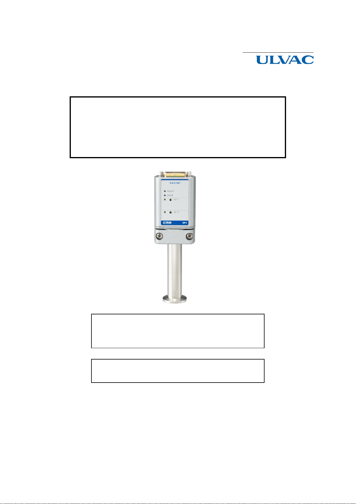
2. FEATURES OF SP1.................................................................................................................... 1
3. SPECIFICATIONS AND COMPONENTS ................................................................................ 2
3.1. Key Specifications ....................................................................................................... 2
3.2. Standard Accessories ................................................................................................... 3
3.3. Options......................................................................................................................... 3
4. NOMENCLATURE AND FUNCTIONS.................................................................................... 4
4.1. Assembly...................................................................................................................... 4
4.2. Front Panel ................................................................................................................... 5
4.3. Input/Output Connector ............................................................................................... 6
5. INSTALLATION......................................................................................................................... 7
5.1. Preparations.................................................................................................................. 7
5.2. Installation.................................................................................................................... 7
5.2.1. Installing the sensor head to the sensor unit......................................................... 7
5.2.2. Installing the sensor unit ...................................................................................... 8
5.2.3. Electrical connection.......................................................................................... 10
6. CAUTIONS IN HANDLING .................................................................................................... 11
7. OUTPUT SIGNALS.................................................................................................................. 12
7.1. Setpoint actuating signal [SET-1 ON/OFF][SET-2 ON/OFF]................................... 12
7.2. Filament open signal [ERR ON/OFF]........................................................................ 12
8. SETTING OF SETPOINT ......................................................................................................... 13
9. FUNCTIONS ............................................................................................................................. 15
9.1. Setpoint [SET-1 ON/OFF] [SET-2 ON/OFF]............................................................ 15
9.1.1. Setpoint .............................................................................................................. 15
9.1.2. Setting of setpoint .............................................................................................. 15
9.1.3. Setpoints of measuring unit and display unit ..................................................... 15
9.2. Open Detection [ERR ON/OFF]................................................................................ 15
9.2.1. What is open detection? ..................................................................................... 15
9.2.2. Confirmation of open filament........................................................................... 15

VI
9.2.3. When the display unit is used............................................................................. 15
9.3. Measurement Value Output ....................................................................................... 16
9.3.1. Measurement value voltage output form............................................................ 16
9.3.2. Measurement value outputs in each condition ................................................... 16
10. TROUBLESHOOTING..................................................................................................... 17
11. WARRANTY..................................................................................................................... 19
12. CERTIFICATE OF DECONTAMINATION.................................................................... 20
13. China RoHS Declaration.................................................................................................... 21
14. APPENDIX........................................................................................................................ 22
14.1. Principles of Operation .............................................................................................. 22
14.2. Types of Gas Measured and Indication...................................................................... 23
14.3. Pressure-Measurement Value List ............................................................................. 25
14.4. Related Drawings....................................................................................................... 27
Fig. 4-2 Front panel........................................................................................................................... 5
Fig. 4-3 Input/output connector pin arrangement.............................................................................. 6
Fig. 5-1 Installing the sensor head..................................................................................................... 7
Fig. 5-2 Installing SP1....................................................................................................................... 9
Fig. 5-3 Equivalent circuit in the power supply .............................................................................. 10
Fig. 7-1 Signal output internal circuit diagram................................................................................ 12
Fig. 9-1 Sensor head (WP-01, 02, 03, 16) filament connection diagram ........................................ 15
Fig. 9-2 Pressure-measurement value output graph ........................................................................ 16
Fig. 14-1 Indications of various types of gas................................................................................... 24
Fig. 14-2 Compatible sensor heads ................................................................................................. 27
Fig. 14-3 Dimensional drawing....................................................................................................... 28
Fig. 14-4 Connection reference drawing (1) ................................................................................... 29
Fig. 14-5 Connection reference diagram (2) ................................................................................... 30

- 1 -
1. Explanation of Terms
In this manual, the following terms have the same meanings.
Setpoint
SETPOINT
SET
Filament
FILAMENT
FIL
Open signal
ERROR
ERR
Communication mode
Remote mode
RS-MODE
CAL function
Calculating function
CAL
2. FEATURES OF SP1
• This sensor unit is a constant temperature type Pirani vacuum gauge that utilizes thermal
conduction of gas.
• The measurable pressure range is 0.4 Pa to 3000 Pa.
• The sensor head and the main unit are integrated in one unit.
• Simple structure having only measuring section. Best suited to applications that require no indicators
if data and signals can be taken out.
• Dedicated indicators are available as option.
• The unit has independent setpoints (two).
• Small in size and does not take up much space for installation.

- 2 -
3. SPECIFICATIONS AND COMPONENTS
3.1. Key Specifications
Name
Pirani vacuum gauge sensor unit Model SP1
Connectable sensor head
One pc.
Compatible sensor head
(See Fig. 14-2 for more information.)
WP-01, WP-02, WP-03, WP-16
Measurable pressure range
4.0 ×10⁻¹ to 3.0 ×10³Pa
Measurement accuracy
(when shipped from factory)
4.0×10⁻¹ Pa
~
1.0×10+1 Pa : ±50%
1.0×10+1 Pa ~5.1×10+1 Pa : ±30%
5.1×10+1 Pa ~7.6×10+2 Pa : ±15%
7.6×10+2 Pa ~1.0×10+3 Pa : ±30%
1.0×10
+3
Pa
~
2.7×10
+3
Pa : ±50%
Sensor head interchangeability
Within ± 3% at filament resistance value
Operating temperature range
10 to 40°C
Control input signal
None
Data output
0 V to 10 VDC, non-linear
Measurement data
Setpoint actuating set value -1: data
Setpoint actuating set value -2: data
Control output signal
Open collector output, negative logic
[24 VMAX, 50 mAMAX, saturation voltage is 1V]
Open signal [ON/OFF]
Setpoint actuating signal -1 [ON/OFF]
Setpoint actuating signal -2 [ON/OFF]
LED display
POWER
SET-1
ERROR
SET-2
Power supply
24 VDC ± 2 V, 90 mA (sensor unit alone)
Input/output connector
D-sub 15-pin (M2.6 screw)
Weight of main unit
190 g (not including sensor head)
Outside dimensions
See Fig. 14-3 Dimensional drawing.

- 3 -
3.2. Standard Accessories
Sensor head
See 3.1 Key Specifications "Compatible
sensor head (Fig. 14-2)".
1 pc
Compatible sensor head
WP-01, WP-02, WP-03, WP-16
Filament material
Pt
Other materials
BS/Ni-plating
Ni
、
Kovar
、
Glass
、
SnSbCu
Permitted leak ratio
1
×
10-8Pa
・
m3/s max
Weight(g)
WP-01
:
about 26
、
WP-02
:
about 45
WP-03
:
about 63
、
WP-16
:
about 77
Internal volume(cm3)
WP-01
:
about 19
、
WP-02
:
about 17
WP-03
:
about 17
、
WP-16
:
about 22
Pressure max
※
1
< 2
×
10+5Pa(abs)
Bakeout
※
2
80
℃
max
Connector
D-sub 15 socket (M2.6 screw)
1 pc
Clamp hood
1 pc
Quick manual
(Ordinary paper)
1 copy
※1:The breakdown pressure of the flange and clamp are to be considered otherwise.
※2:Bakeout temperature is a temperature of the sensor unit. Please remove the electronics or the conversion
cable
※3:WP-04 and WP-05 discontinued producing in August, 2012.
3.3. Options
Display unit
1CH Digital
Model ISG1( 24VDC power supply type)
End of sale: ISP1, ISP2, IAP2
4CH Digital
Model IM1R1(24VDC power supply type)
Model IM2R1(100VAC power supply type)
Display cable
2 m, 5 m, and 10 m (between measuring unit and display unit)
Test results certificate
Calibration certificate
Calibration certificate, JCSS Calibration certificate
Traceability certificate
Calibration certificate, JCSS Calibration certificate

- 4 -
4. NOMENCLATURE AND FUNCTIONS
4.1. Assembly
Fig. 4-1 Assembly
No.
Component
Function
①
I/O connector
I/O connector for power supply, data and signal (D-sub 15-pin)
See Fig. 4-3 for pin No.
②
Screw
Screw for clamp hood (M2.6)
③
Clamp screw
Sensor head clamping screw (M4)
④
Sensor head clamp
Clamp that clamps and fixes the sensor head

- 5 -
4.2. Front Panel
Fig. 4-2 Front panel
No.
Component
Function
①
POWER lamp
(POWER)
Lights when power is supplied to the sensor unit.
②
ERROR lamp
(ERROR)
Lights when the sensor head filament has burnt out.
③
SET-1 lamp
(SET-1)
Lights when setpoint 1 is actuated.
④
SET-2 lamp
(SET-2)
Lights when setpoint 2 is actuated.
⑤
SET-1 setting trimmer
(SET-1)
Sets the value of setpoint 1 by adjustment of trimmer.
⑥
SET-2 setting trimmer
(SET-2)
Sets the value of setpoint 2 by adjustment of trimmer.

- 6 -
4.3. Input/Output Connector
Fig. 4-3 Input/output connector pin arrangement
Terminal
No.
*
Sensor unit Direction of signal Connected to
1
Power supply +24 V
Power
2
Open signal
Remote host display
unit
3
Setpoint actuating signal 1
4
Measuring unit connection check
signal
7
Setpoint 1 set value
8
Measurement value
9
Power ground
Power
10
OUT-COM (Ground)
Remote host display
unit
11
Setpoint 2 actuating signal 2
14
Setpoint 2 set value
15
Ground
* Terminals not mentioned here are not used. Do not make wiring connection to terminals not mentioned
above.

- 7 -
5. INSTALLATION
!
CAUTION
Turn OFF power.
!
CAUTION
Please note the following three points when installing the measuring element
to the Pirani gauge SP1.There is a risk of breakage of gauge head in case of
wrong use.
5.1. Preparations
(1) Unpack the unit and check quantities. (See 3.2 for accessories.)
(2) Check components for possible damage.
5.2. Installation
5.2.1. Installing the sensor head to the sensor unit
Turn the clamp screw to loosen the clamp. Install the sensor head according to the following procedure.
①Insert the sensor head in the direction of pin, as shown in the figure.
②Hold the sensor head with the clamp.
③Tighten the screw to fix the sensor head.
Fig. 5-1 Installing the sensor head

- 8 -
Please note the following three points when installing the measuring element to the Pirani gauge
SP1.There is a risk of breakage of gauge head in case of wrong use.
1 Please tightening the Clamping screw till eliminate the rattling. Do not tighten more when is enough
tight. Recommend torque : 0.4N・m or less
2 Please tighten the clamping screw in parallel with the same torque tight.
Do not tight the screw till the end, one by one. Tighten both clamp screw with same torque.
3 Install the sensor head to the sensor unit SP1, caution under 3 points. If don’t caution, Sensor head
may be damaged.
Install the sensor head up to the mechanical stop, causing the sensor to leak.
Connecting is insufficient
=>the sensor to leak
Connecting is sufficien
5.2.2. Installing the sensor unit
Install the sensor head to the gauge port of the vacuum system.
!
NOTICE
Provide ventilation.
!
NOTICE
Keep out foreign matter.
!
NOTICE
Pay attention to operating environment.
!
NOTICE
Check connection.
(1) Measuring position
This gauge measures the static pressure in the position where the sensor head is installed. If
there is a gas flow, source of outgas or intense electrons or ions in the vacuum system, carefully
select the measuring position so that measurement is least affected by them.
Because of the principles of the Pirani gauge, the measurement value is affected by the ambient
temperature of the sensor head. Be careful that the ambient temperature deviates noticeably
from the temperature at the time of calibration (25°C).
(2) Installing the sensor head
• Install the sensor head in such a manner that the plane of the sensor mounting port is parallel to
gas flow. Ensure that gas does not enter the sensor head in the form of beam. (See Fig. 5-2)
• Please attached to the vertical direction as much as possible. (See Fig. 5-2.)
• The sensor head filament is as thin as 25 µm. Avoid use in a place where vibration is at a high
level. Mechanical impact is responsible for filament burnout in most cases.
On the structure of the sensor, it is vulnerable to vibration in the X direction of Figure 5-2. It
must be installed so that the vibration in the X direction is not applied.

- 9 -
• O-rings to be used in installing the sensor head should be as free from outgas as possible. Use
of rubber pipes or grease that release much outgas can be a cause of error.
On the structure of the sensor, it is vulnerable to
vibration in the X direction. It must be installed
so that the vibration in the X direction is not
applied.
Fig. 5-2 Installing SP1

- 10 -
5.2.3. Electrical connection
Make electrical connection referring to the pin arrangement on page 6.
!
CAUTION
Check line voltage.
!
NOTICE
Pay attention to operating conditions.
Cautions:
• Install the sensor head first and then make electrical connection.
• The power GND [9-pin], OUT-COM [10-pin] and GND [15-pin] are common after being filtered
inside. Use power +24 V [1-pin] and power GND [9-pin] for connection of the power line. If
other GND is used, the instrument may be subject to noise.
• Fix the cable so that undue force is not exerted to the connection of the cable.
• Securely tighten the connector fixing screws.
• In supplying power to the sensor unit, do not mistake pin numbers. (See Fig. 4-3 for pin
arrangement.)
Fig. 5-3 Equivalent circuit in the power supply
+5V
+24V
A
12
A
12
A
12
A
12
11:Setpoint-2 signal_ON/OFF
3:Setpoint-1 signal_ON/OFF
4:Measuring unit connection
15:GND
10:OUT-COM
2:ERROR_signal-ON/OFF
PLC or Computer
Interior
G-TRAN_interior
check signal-OK/NG

- 11 -
6. CAUTIONS IN HANDLING
• Make measurement more than one minute after turning on power and the output is stabilized.
• For precision measurement, wait for more than 10 minutes after turning on power and the
temperature equilibrium of the sensor head is established.
• Do not turn off the power to the sensor head during a sequence of measurements.
• The characteristics of the sensor head may change if it is exposed to a chemically active or highly
adsorptive gas. In that event, fill the sensor head with nitrogen or inert gas or dry air with the sensor
head energized with power and pump it. Repeat this operation (purging). It may be restored to
the original condition. However, do not spray such gas to the opening of the sensor head for purging.
If there is no prospect of the characteristic being restored, replace the sensor head with a new one.
• The Pirani gas is sensitive to all types of gas, but the sensitivity varies with the type of gas. The
unit displays pressure by assuming gas to be air.

- 12 -
7. OUTPUT SIGNALS
Signals are outputted from the connector at the top of the sensor unit in the open collector format. Fig.
7-1 shows its internal circuit.
7.1. Setpoint actuating signal [SET-1 ON/OFF][SET-2 ON/OFF]
The internal transistor is actuated when the measured value is lower than the set pressure. (Lo output
when setpoint is ON.)
See Fig. 4-3 for the pin numbers. (→See page 15 for functions.)
7.2. Filament open signal [ERR ON/OFF]
Transistor is actuated if the sensor head filament burns out (Lo output when open). At this time, the
setpoint output is off.
See Fig. 4-3 for the pin numbers. (→See page 15 for functions.)
Output rating [24 VMAX, 50 mAMAX, saturation voltage is 1V]
Fig. 7-1 Signal output internal circuit diagram
+5V
+24V
A
1 2
A
1 2
A
1 2
A
1 2
11:Setpoint-2 signal_ON/OFF
3:Setpoint-1 signal_ON/OFF
4:Measuring unit connection
15:GND
10:OUT-COM
2:ERROR_signal-ON/OFF
PLC or Computer
Interior
G-TRAN_interior
check signal-OK/NG
Other manuals for G-Tran Series
11
This manual suits for next models
1
Table of contents
Other Ulvac Accessories manuals