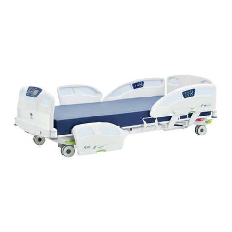
Umano Medical OOK Snow FL36 User manual

2022/03 | 74-36121-ENG R2
User manual
FL36
FL36-SC
MH


2022/03 | 74-36121-ENG R2
User manual
FL36
FL36-SC
MH

Copyright 2022 Umano Medical Inc.
All Rights Reserved.
No part of this publication may be reproduced, distributed, or transmitted in any form or by any means, including photocopying, recording,
or using electronic or mechanical methods, without the prior written permission of the publisher, except in the case of brief quotations
embodied in critical reviews and certain other noncommercial uses permitted by copyright law. For permission request, write to the publisher
at the address below.
Original instructions
The authorized representatives for the following markets can be contacted at:
European Union:
EMERGO EUROPE
Prinsessegracht 20
2514 AP The Hague
The Netherlands
UK Responsible Person Contact:
Emergo Consulting (UK) Limited
c/o Cr360 - UL International
Compass House, Vision Park Histon
Cambridge CB24 9BZ
United Kingdom
Phone: +44(0) 1223 772 671
Email: [email protected]
Australia:
AUSTRALIAN SPONSOR
Emergo Australia Level 20, Tower II
Darling Park 201 Sussex Street
Sydney, NSW 2000 Australia
This manual is used for different markets/jurisdiction and the information covers various features and options for the ooksnow MH bed.
This publication is also available in other languages.
Use of the masculine form in this document refers to both men and women.
Printed in Canada
EC REP UK RP

USER MANUAL — 74-36121-ENG R2 3
TABLE OF CONTENTS
INTRODUCTION.......................................5
Product description .....................................5
Product intended use ..................................5
Contact .........................................................6
Application environments and
limitations .....................................................7
Product illustration ......................................8
Technical specications..............................9
EMC information ..........................................11
Symbols and denitions .............................13
Pictograms and denitions.........................15
Safety measures ..........................................19
Gradation and denition of safety
measures.................................................19
Safety measures......................................19
GETTING STARTED...............................23
Steps list for set up......................................23
Zeroing procedures .................................24
Conguration steps for server connection
settings (optional) ....................................26
OPERATING INSTRUCTIONS.........27
Power up and modes of operation .............27
System signals and messages ................29
Transporting bed..........................................29
Base, frame and litter ..................................30
Brake, neutral and steer ..........................30
Safe lock braking system (optional).........30
Floor mount (optional) .............................31
Foot control system (optional) .................31
Motion interrupt (optional)........................31
Drainage bag support ..............................31
Accessory and equipment sockets ..........32
Accessory socket caps (optional) ............32
Covered restraint points (optional) ..........32
Motion key lock (optional)........................32
Patient restraint location ..........................33
Bumpers ..................................................34
Bumpers with side view lights
(optional)..................................................34
Power cord support brackets...................34
Short power cord (optional) .....................34
CPR release (optional) ............................35
Control on frame (optional)......................35
Nightlight (optional)..................................36
Bed extender (optional) ...........................36
Connectors, ports and outlets....................37
Nurse call connector (optional)................37
Nurse call bell port (optional)...................37
Communication port (optional) ................37
Auxiliary power outlets and USB port
(optional)..................................................38
Head and foot ends siderails ......................39
Filled siderails and boards (optional).......39
Backrest section angle degree
indicator ...................................................39
Positioning siderail ..................................39
Patient mobilization helper (optional) ......40
Patient siderail controls ...........................41
Caregiver siderail controls .......................42
Patient control (optional)..........................43
Headboard and footboard ...........................44
Built-in transport handles.........................44
Headboard...............................................44
Boards blocking fasteners (optional) .......44
Integrated pump holder ...........................44
Footboard control ....................................45
Footboard control with display screen .....48
Bed exit detection levels .............................48

TABLE OF CONTENTS
4USER MANUAL — 74-36121-ENG R2
SMART SCREEN DISPLAY ...............49
ACCESSORIES .........................................69
Mattress extension for bed extender -
DM64505 and DM64506 ...............................70
Siderail pads - DM64515 and DM64516......71
Fixed IV pole 3/4" diameter - FA64506 .......73
Folding IV pole 3/4" diameter - FA64507....74
1" xed IV pole for 3/4" socket - FA64522 .75
1" xed IV pole for 1" socket - FA64508 ....76
Left 1" folding IV pole for 1" socket -
FA64521 ........................................................77
Right 1" folding IV pole for 1" socket -
FA64523 ........................................................78
1/2" IV pole adapter - FA64514....................79
Oxygen bottle holder - FA64505 .................80
Oxygen bottle holder with clamp -
FA64527 ........................................................81
Patient helper - FA64504 .............................82
PREVENTIVE MAINTENANCE........83
Preventive maintenance annual
checklist........................................................84
CLEANING....................................................85
Cleaning........................................................85
Disinfection ..................................................85
Mattress, mattress extension and
siderail pads cleaning and care..................85
WARRANTY.................................................87
Shipment receipt......................................87
Product return..........................................87
Limited warranty ......................................87
Parts and service.....................................87
INDEX ..............................................................88

USER MANUAL — 74-36121-ENG R2 5
INTRODUCTION
This manual includes instructions and information that are necessary for a normal and secure use of the
ook<snow>>MH bed designed for mental health environment, model FL36 and FL36-SC. Reading and
understanding of instructions and information included in this manual, or other documents supplied with the
product, are required prior to usage, or prior to perform maintenance on the equipment.
Product description
The ook<snow>>MH, model FL36 and FL36-SC, is an AC-powered medical bed with 4 built-in electric DC
actuators and controls that is designed for medical purposes in mental health care units and/or environments.
The height and surface contours are adjustable. The patient sleep surface can be 80" long or, up to 84" or 90"
with an integrated bed extender and cushion. The bed conguration includes movable and latchable siderails,
or patient mobilization helper, and tamper-resistant fasteners. Optionally, the bed can be congured without
siderails, with permanently attached headboard and footboard and/or short or quick-disconnect power cord to
suit specic mental health care needs.The product offers a range of other options and accessories outlined in the
manuals, including, but not limited to: bed exit system, bed status monitoring, integrated bed extender, motion
interrupt system, oor mount xation and, lled siderails and boards. An integrated scale system is also offered
for healthcare professionals to follow patient weight uctuation. The overall capacity of the bed goes up to is
600 lb/272 kg. The expected life under normal usage and maintenance is 15 years.
A connectivity option is also offered on the bed; a communication board is integrated to the bed which allows to
send information to the Umano Connect web application server through an Ethernet or Wi-Fi connection using
an internal communication protocol. The hospital personnel can access the web application through an Internet
browser to display the beds information such as bed statuses, alarm, weight logs, etc. The hospital can integrate
the beds to their Real-Time locating system (RTLS) using the Bluetooth Low Energy (BLE) or the Wi-Fi tag
conguration. An Application Programming Interface (API) is available for the hospital to access the beds’ data
and to send information to their own system or platform.
The ook<snow>>MH, model FL36-SC, shares the same construction as the FL36, but is however intended for
markets where local regulations require scale systems conformity to metrological controls (OIML R76-1).
Product intended use
The ook<snow>>MH, model FL36 and FL36-SC, is intended to be used as a patient bed for rest/sleep as well as
for alleviation of, or compensation for, an injury, an handicap or the patient condition. It is to be used with patients
that may have special safety needs, such as patients with mental health illness, in mental health care units and/or
environments. It is designed and intended for procedures and usage in, but not limited to, the following adapted
health care environments: intensive or acute care, professional long-term care, outpatient care, rehabilitation
centers and, recovery or therapeutic areas. Optional specic features were designed and are intended for
patients that may be at risk of self-harm. Those features involve application restriction such as: the short power
cord, permanently attached headboard and footboard and bed without siderails. Application environments and
limitations are detailed in next section (page 7).
The bed is designed for the use of one single person and, to be used with a sleep surface and can be used for
patient transportation between bays and procedural rooms. Users are health care providers, which can use all
bed operations, patient and bystanders, which can use unlocked bed motion functions, and maintenance staff.
Only trained personnel or service technician should perform installation or maintenance on the bed.

INTRODUCTION
6USER MANUAL — 74-36121-ENG R2
Contact
The manufacturer can be contacted for any assistance regarding the set up or the use of the bed, its maintenance.
Reporting problems:
The user and/or patient should report any suspected serious incident related to the device by informing the
manufacturer and the competent authority of the member state in which the serious incident has occurred.
Umano Medical Inc.
230 boulevard Nilus-Leclerc, L’Islet QC G0R 2C0 CANADA
T: (418) 247-3986
T: (844) 409-4030

INTRODUCTION
USER MANUAL — 74-36121-ENG R2 7
Application environments and limitations
Application environments
No Description ook<snow>>MH
1
Intensive/critical care provided in a hospital where 24 h medical supervision and
constant monitoring is required and provision of life support system/equipment
used in medical procedures is essential to maintain or improve the vital functions
of the patient.
Applicable*
2
Acute care provided in a hospital or other medical facility where medical
supervision and monitoring is required and medical equipment used in medical
procedures is often provided to help maintain or improve the condition of the
patient.
Applicable*
3
Long-term care in a medical area where medical supervision is required and
monitoring is provided if necessary and medical equipment used in medical
procedures may be provided to help maintain or improve the condition of the
patient.
Applicable
4Care provided in a domestic area where medical equipment is used to alleviate
or compensate for an injury, disability or disease. Not Applicable
5
Outpatient (ambulatory) care, which is provided in a hospital or other medical
facility, under medical supervision where medical equipment, is provided for
the need of persons with illness, injury or disability for treatment, diagnosis or
monitoring.
Applicable
Mental
care
speciality
Specialized care, which is provided in a hospital or other medical facility, for
patients with limited permissions and subject to tamper with their environment
with intended or unintended objective to generate physical harm (induced to self
or others). Ex: Psychiatric wards, penitentiary clinic.
Applicable**
* The use of the permanently attached headboard option is not intended for application environments 1 and 2 as
some emergency procedures might be delayed to gain access to patient’s head.
** The options of short power cord length and bed without siderails are limited to mental care specialty application
environments. These options decrease the number of possible ligature points on the bed perimeter and shall be
used only with patients requiring this type of prevention. Extra care is necessary from the caregivers personnel
with these options in order to prevent/avoid the risk of power cord damages and/or the risk of patients falls or
injuries.

Product illustration
Item Description Item Description
1 Headboard 2 Backrest section
3 CPR release handle (optional) 4 Nurse call plug (optional)
5 Power cord 6 Siderail control
7 Angle indicator 8 Brake, neutral and steer pedal
9 Drainage bag support 10 Siderail release handle
11 Patient siderail control 12 Footboard
13 Footboard control 14 Bumper
15 Frame control (optional) 16 Bed extender handle (optional)
17 Patient restraint location 18 Auxiliary power outlets (optional)
19 USB connector (optional) 20 Communication port (optional)
21 Patient restraint location (optional) 22 Drainage bag support (optional)
23 Foot control (optional) 24 Nurse call bell port (optional)
21
1
4
2
7
8
22
10
15
3
13
11
14
12
16
8
17
5
14
18
17 3
19
20
23
24
INTRODUCTION
8USER MANUAL — 74-36121-ENG R2
9
10 6
21

INTRODUCTION
USER MANUAL — 74-36121-ENG R2 9
Technical specifications
Weights and dimensions
Bed weight (based on features) 303 lb to 438 lb 137 kg to 199 kg
Safe working load (including patient, mattress and
accessories) 600 lb 272 kg
Maximum mattress weight 44 lb 20 kg
Maximum accessories weight 100 lb 45 kg
Maximum patient weight 456 lb 207 kg
Length
including bumpers (80" sleep surface)
including extension and bumpers (84"/90" sleep surface)
88"
92" / 98"
224 cm
234 cm / 249 cm
Width
with siderails up
with siderails down
without siderails
41.3"
39.25"
38.9"
105 cm
100 cm
98.8 cm
Height *
highest with 5" dual casters
lowest with 5" dual casters
highest with other casters
lowest with other casters
highest with oor mounted xation
lowest with oor mounted xation
30"
10"
31.6"
11.6"
30"
10"
76.2 cm
25.4 cm
80.3 cm
29.5 cm
76.2 cm
25.4 cm
Patient sleep surface
width
length
extended length
35"
80"
84" / 90"
88.9 cm
203.2 cm
213.4 cm / 228.6 cm
Under bed central zone clearance 5" 12.7 cm
Angulations
Backrest section 0° to 60°
Thigh section 0° to 30°
Trendelenburg / reverse Trendelenburg -16° to +16°
Recommended mattress
Foam mattress
length
extended length
width
maximum thickness
ILD perimeter
80"
84" / 90"
35"
6"
75
203.2 cm
213.4 cm / 228.6 cm
88.9 cm
15.24 cm
75
Specialty or therapeutic mattress
Use foam mattresses recommendations to orient the choice of a therapeutic mattress. The decision for a therapeutic
mattress should be documented by the clinical staff, based on a thorough patient clinical assessment, and should consider
the entrapment risk and fall hazards related to the mattress combination.
* The stroke of the elevation system can be set to adjust the minimum height. Instructions are listed in the Maintenance Manual under Bed
height settings.

INTRODUCTION
10 USER MANUAL — 74-36121-ENG R2
Environmental conditions
Use
ambient temperature
relative humidity
atmospheric pressure
50 °F to 104 °F
5 to 95% without
condensation
500 to 1060 hPa
10 °C to 40 °C
5 to 95% without
condensation
500 to 1060 hPa
Transport and storage
ambient temperature
relative humidity
atmospheric pressure
-40 °F to 158 °F
10% to 100%
500 hPa to 1060 hPa
-40 °C to 70 °C
10% to 100%
500 hPa to 1060 hPa
Maximum altitude 6,562 ft 2000 m
Electrical requirements
Electrical and mechanical requirements
comply with standards: IEC60601-1, CAN/CSA C22.2
60601-1, UL60601-1, IEC60601-1-2, IEC60601-2-52,
CAN/CSA C22.2 60601-2-52
Degree of protection IPX4
Degree of protection against electrical shocks Class I, Type B
Scale accuracy 0.5% with a difference of maximum 1.1 lb / 0.5 kg
Scale accuracy (EC) EN45501:2015 / OIML R76-1 Class III MAX 272.5 kg MIN
10 kg e = 0.5 kg
The bed is a manually operated device with very minor
vibration level under 0.5m/s2
Voltage 120 V AC, 60 Hz / 220-240 V AC, 50-60 Hz
Amperage (includes power outlet and powered system) 120 V AC: Bed 9.25 A
220-240 V AC: Bed 4.15 A
Current leakage Conform with standards IEC60601-1
Battery type sealed rechargeable lead acid battery 1.2 Ah, 2 x 12 V
Actuator duty cycle 1 minute On, 9 minutes Off
Auxiliary power outlets 120 V AC / 5 A
220-240 V AC / 2 A
USB type A charger 120V bed: 5V DC / 3.1A
220-240V bed: 5V DC / 0.75A
Wi-Fi emitter specications
Chipset ESP32 : ESPWROOM32U
IEEE 802.11 b/g/n
Bands 2.4 GHz - 2.5 GHz
Encryption TLS
Authentication WPA/WPA2, WPA2 - Enterprise modes, EAP-PEAP,
EAP-TTLS and EAP-TLS
IC IC ID : 1C21098-ESP32WROOM32U - RSS-247
FCC FCC ID : 2AC77-ESP32WROOM32U -
15 CFR Part 15.247

INTRODUCTION
USER MANUAL — 74-36121-ENG R2 11
EMC information
Guidance and manufacturer’s declaration - emission
The “FL36 Medical Bed” is intended for use in the electromagnetic environment specied below. The customer or user of
the “FL36 Medical Bed” should ensure that it is used in such an environment.
Emission test Compliance Electromagnetic environment - guidance
RF Emissions
CISPR 11 Group 1
The “FL36 Medical Bed” uses RF energy only for its internal
function. Therefore, its RF emissions are very low and are
not likely to cause any interference in nearby electronic
equipment.
RF Emissions
CISPR 11 Class B
The “FL36 Medical Bed” is suitable for use in all
establishments, other than domestic, and those directly
connected to the public low-voltage power supply network
that supplies buildings used for domestic purposes.
Harmonics
IEC 61000-3-2 Class A
Flicker
IEC 61000-3-3
Pst: 10 minutes
Plt: 120 minutes
Guidance and manufacturer’s declaration – immunity
The “FL36 Medical Bed” is intended for use in the electromagnetic environment specied below. The customer or user of
the “FL36 Medical Bed” should ensure that it is use in such an environment.
Immunity test IEC 60601 test level Compliance level Electromagnetic
environment -
guidance
ESD
IEC 61000-4-2
±8kV Contact
±15kV Air
±8kV Contact
±15kV Air
Floors should be wood,
concrete or ceramic tile. If
oors are synthetic, the r/h
should be at least 30%
EFT
IEC 61000-4-4 ±2kV Mains ±2kV Mains
Mains power quality
should be that of a typical
commercial or hospital
environment.
Surge
IEC 61000-4-5
±1kV Differential
±2kV Common
±1kV Differential
±2kV Common
Mains power quality
should be that of a typical
commercial or hospital
environment.
Voltage Dips/Dropout
IEC 61000-4-11
0% Dip for
0.5 Cycle
0% Dip for
1 Cycle
70% Dip for
25 Cycles
0% Dip for
250 Cycles
0% Dip for
0.5 Cycle
0% Dip for
1 Cycle
70% Dip for
25 Cycles
0% Dip for
250 Cycles
Mains power quality
should be that of a typical
commercial or hospital
environment. If the user
of the “FL36 Medical
Bed” requires continued
operation during power
mains interruptions, it
is recommended that
the “FL36 Medical Bed”
be powered from an
uninterruptible power supply
or battery.
Power Frequency
50/60Hz
Magnetic Field
IEC 61000-4-8
30A/m 30A/m
Power frequency magnetic
elds should be that of
a typical commercial or
hospital environment.

INTRODUCTION
12 USER MANUAL — 74-36121-ENG R2
Guidance and manufacturer’s declaration - immunity
The “FL36 Medical Bed” is intended for use in the electromagnetic environment specied below. The customer or user of
the “FL36 Medical Bed” should ensure that it is used in such an environment.
Immunity test IEC 60601 test level Compliance level
Electromagnetic
environment -
guidance
Conducted RF
IEC 61000-4-6
Radiated RF
IEC 61000-4-3
IEC60601-1-2 (2014)
3 Vrms
150 kHz to 80 MHz
3 V/m
80 MHz to 2.7 GHz
(V1)=3Vrms
(E1)=3V/m
Portable and mobile
communications equipment
should be separated from
the “FL36 Medical Bed” by
no less than the distances
calculated/listed below:
Conform levels tested:
385MHz: 27V/m
710MHz, 745MHz, 780MHz:
9V/m
450MHz, 810MHz, 870MHz,
930MHz: 28V/m
1.72GHz, 1.845GHz,
1.97GHz, 2.45GHz: 28V/m
5.24GHz, 5.5GHz,
5.785GHz: 9V/m

INTRODUCTION
USER MANUAL — 74-36121-ENG R2 13
Symbols and definitions
Different symbols are used on the product and in this manual. Their purpose is to inform the user on functional
details or on safety related measures.
!
Indicates the medical device
manufacturer
Indicates the need for the user to
consult the instructions for use for
cautionary information such as
warnings and precautions that cannot
be presented on the medical device
itself
T 10A L 125V
Indicates the date of manufacture Indicates a fuse of 10 amperes /
125 volts
REF
5 A 250V
Indicates the manufacturer’s
catalogue number so that the medical
device can be identied
Indicates a breaker of 5 amperes /
250 volts
Indicates a terminal which is intended
for connection to an external
conductor for protection against
electric shock in case of a fault, or the
terminal of protective earth (ground)
electrode
Indicates a warning of foot crushing
hazard
Indicates that on the rating plate, the
equipment is suitable for alternating
current only to relevent terminals
Indicates a warning of hand crushing
hazard
IPX4
T 5A L 250V
Indicates a fuse of 5 amperes /
250 volts
Indicates the level of protection
against liquid splash
2 A 250V
Indicates a breaker of 2 amperes /
250 volts
Indicates a Type B applied part
complying with the specied
requirements of this standard to
provide protection against electric
shock, particularly regarding allowable
patient leakage current and patient
auxiliary current

INTRODUCTION
14 USER MANUAL — 74-36121-ENG R2
Indicates the need for the user to
consult instructions for use
Indicates a general mandatory action
Indicates that the equipment has been
independently tested and meets the
applicable published safety standard
Indicates the need for the user to
follow instructions for use
Indicates that when disposed,
the equipment must be collected
separately in accordance with the
European Directive 2002/96 relatively
to waste electrical and electronic
equipment (WEEE)
Indicates the accessories weight
!
Indicates the patient maximum weight
for a safe use of the equipment
!
Indicates the total maximum charge
for a safe use of equipment
III Indicates the scale system accuracy
class according to OIML R76-1 and
EN45501:2015
2797
Indicates compliance with standard
93/42/EEC Medical Devices
MYY 0050
T12175
Indicates compliance with standard
2014/32/EC Non Automatic Weighting
Instrument
Indicates compliance with
Regulation (EU) 2017/745
Indicates that device is
United Kingdom Conformity Assessed
(UKCA)
MYY 0126
UK 3117
Indicates compliance with standard
2014/32/EC Non Automatic Weighting
Instrument for United Kingdom
MD
Indicates the product is a Medical
Device according to EU Medical
Device Regulation 2017/745
0086
Indicates compliance with directive
93/42/EEC Medical Devices

INTRODUCTION
USER MANUAL — 74-36121-ENG R2 15
30°
Pictograms and definitions
Different pictograms are used on the product and in this manual. Their purpose is to facilitate the reading and the
understanding of the different functionalities to the user. If bed is equipped with screen, additional pictograms may
be displayed in different menus. Refer to Footboard control (page 45) section if required.
Button for elevation of section
illustrated below the button
Button for lowering of section
illustrated over the button
Button for reverse Trendelenburg
positioning
Button for Trendelenburg
positioning
Illustration indicating possible
activation of Backrest section
AND/OR the Thigh Section per
use of one or both buttons located
over or below the pictogram
Illustration indicating possible
activation of Hi-Lo per use of
button located over or below the
pictogram
Button for the vascular foot
positioning
Button for patient sleep surface
at positioning
Button for a 30-degree angle
positioning of the Backrest section
Button for chair positioning
Button for activation or
deactivation of room lights
Button for activation or
deactivation of controls backlight
or reading light
Button with LED indicator for lock
(On), unlock (Off), of patient and
siderail motion control
Illustration with LED indicator for
battery supply and battery charge
level indication
Illustration with LED indicator
indicating power supply
Button for Nurse Call

INTRODUCTION
16 USER MANUAL — 74-36121-ENG R2
Inform
1
2
AUTO
6''
35''
4
3
2
1
Illustration for the Inform system
settings or usage
Button for bed exit control system
auto-arm of pre-selected degree
of detection
Button for selection of bed exit
control degree of detection for
Detection 2 - BED EXITING
Button for selection of bed exit
control degree of detection for
Detection 1 - OUT-OF-BED
Illustration indicating group of
buttons for bed exit control system
settings
Button for selection of audio
signal level
Illustration indicating the
recommended mattress thickness
Illustration indicating the
recommended mattress width
Button for selection of audio
signal type
Illustration with LED indicators for
active selection of tone
Button with LED indicator for
activation/deactivation, of bed exit
control system
Illustration with LED indicators
for sound level from mute to high
level
Illustration indicating patient is
subject to falls
Illustration indicating selection of/
activated bed exit control degree
of detection for Detection 3 -
MOVEMENT
5A 120V
~
60Hz
Illustration indicating location of
auxiliary outlets
!Illustration indicating adjustable
power cord length
Illustration indicating patient
restraints location
!
Illustration indicating xed
headboard and footboard

INTRODUCTION
USER MANUAL — 74-36121-ENG R2 17
Illustration indicating that patient
has one or more allergies
!
COM
Illustration indicating interdiction
to drink liquids
Illustration indicating that two
people are required to move the
patient
Illustration indicating patient is
subject to confusion
Illustration indicating location for
the motion lock switch and the
possibility to lock or unlock the
bed motions with a key
Illustration indicating location for
communication port
Illustration indicating interdiction
to change bed conguration
Illustration indicating location for
communication port
Illustration indicating that patient
is subject to pressure ulcers
Illustration indicating the necessity
to monitor blood pressure
Illustration indicating the
possibility to turn ON or OFF
the nightlights using a switch
Illustration indicating location for
nurse call connector
Illustration indicating necessity to
monitor blood sugar level
2A 220-240V
~
50/60Hz
Illustration indicating international
auxiliary power outlet
Illustration indicating location to
connect patient control
Illustration indicating location to
store the patient control

INTRODUCTION
18 USER MANUAL — 74-36121-ENG R2
Illustration indicating that the
bed is disconnected from the
connectivity application
Illustration indicating that the bed
is disconnected from the internet
connection by cable
Illustration indicating that the bed
is connected to the connectivity
application
Illustration indicating that the bed
is disconnected from the wi
Illustration indicating that the bed
is connected to the wi
Illustration indicating that the bed
is connected to internet by cable
Illustration indicating that the bed
is connected to internet by cable
and by wii
This manual suits for next models
3
Table of contents
Other Umano Medical Medical Equipment manuals
Popular Medical Equipment manuals by other brands

Bausch & Lomb
Bausch & Lomb Akreos AO Loading Instructions

Advanced Instruments
Advanced Instruments OsmoTECH XT user guide

natus
natus Dantec Keypoint Hardware Instructions for Use

cefar
cefar Rehab X2 operating instructions

Sunrise Medical
Sunrise Medical switch-IT owner's manual

ThermaZone
ThermaZone 003-99 quick start guide