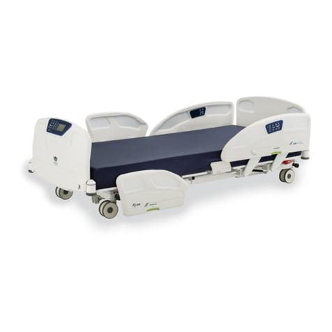
Umano Medical ooksnow FL36 User manual

2017/10 | 74-36105-ENG R5
User manual
FL36
MH


2017/10 | 74-36105-ENG R5
User manual
FL36
MH

Copyright 2017 Umano Medical Inc.
All Rights Reserved.
No part of this publication may be reproduced, distributed, or transmitted in any form or by any means, including photocopying, recording,
or using electronic or mechanical methods, without the prior written permission of the publisher, except in the case of brief quotations
embodied in critical reviews and certain other noncommercial uses permitted by copyright law. For permission request, write to the publisher
at the address below.
Manufactured by:
Umano Medical Inc.
230 boulevard Nilus-Leclerc, L’Islet QC G0R 2C0 CANADA
This publication is also available in other languages.
Use of the masculine form in this document refers to both men and women.
Printed in Canada

USER MANUAL — 74-36105-ENG R5 3
TABLE OF CONTENTS
INTRODUCTION.......................................5
Product description .....................................5
Product intended use ..................................5
Contact .........................................................5
Product illustration ......................................7
Technical specications..............................8
EMC information ..........................................10
Symbols and denitions .............................12
Pictograms and denitions.........................14
Safety measures ..........................................17
Gradation and denition of safety
measures.................................................17
Safety measures......................................17
GETTING STARTED...............................21
Steps list for set up......................................21
Zeroing procedures .................................23
OPERATING INSTRUCTIONS.........25
Power up and modes of operation .............25
System signals and messages ................26
Transporting bed..........................................26
Base, frame and litter ..................................27
Brake, neutral and steer .........................27
Floor mounted xation (optional) .............27
Motion interrupt (optional)........................28
Drainage bag support ..............................28
Accessory and equipment sockets ..........28
Anti-theft caps (optional)..........................28
Patient restraint location ..........................28
Reduced ligature attachment points
(optional)..................................................29
Bumpers ..................................................29
Bumpers with side view lights
(optional)..................................................29
Power cord support brackets...................29
Short power cord (optional) .....................30
CPR release (optional) ............................30
Nurse call connector (optional)................30
Auxiliary power outlets and USB port
(optional)..................................................31
Communication port (optional) ................32
Control on frame (optional)......................32
Nightlight (optional)..................................32
Bed extender (optional) ...........................33
Head and foot ends siderails ......................34
Siderails and boards without
openings (optional) ..................................34
Backrest section angle degree
indicator ...................................................34
Positioning siderail ..................................34
Patient mobilization helper (optional) ......35
Patient siderail controls ...........................36
Caregiver siderail controls .......................37
Patient control (optional)..........................38
Headboard and footboard ...........................39
Built-in transport handles.........................39
Headboard...............................................39
Boards blocking fasteners (optional) .......39
Integrated pump holder ...........................39
Footboard control ....................................40
Footboard control with display screen .....43
Detailed screen functions (SW 1.3) .........45
Detailed screen functions (SW 2.0) .........57
ACCESSORIES .........................................73
Mattress extension for bed extender -
DM64505 and DM64506 ...............................74
Siderail pads - DM64515 and DM64516......75
Fixed IV pole 3/4" diameter - FA64506 .......77
Folding IV pole 3/4" diameter - FA64507....78

1" xed IV pole for 3/4" socket -
FA64522 ........................................................79
1" xed IV pole for 1" socket - FA64508 ....80
Left 1" folding IV pole for 1" socket -
FA64521 ........................................................81
Right 1" folding IV pole for 1" socket -
FA64523 ........................................................82
Oxygen bottle holder - FA64505 .................83
Patient helper - FA64504 .............................84
PREVENTIVE MAINTENANCE........85
Preventive maintenance annual
checklist........................................................86
CLEANING....................................................87
Cleaning........................................................87
Disinfection ..................................................87
Mattress, mattress extension and
siderail pads cleaning and care..................87
WARRANTY.................................................89
Shipment receipt......................................89
Product return..........................................89
Limited warranty ......................................89
Parts and service.....................................89
INDEX ..............................................................90

USER MANUAL — 74-36105-ENG R5 5
INTRODUCTION
This manual includes instructions and information that are necessary for a normal and secure use of the
ook<snow>>MH bed designed for mental health environment, model FL36. Reading and understanding of
instructions and information included in this manual, or other documents supplied with the product, are required
prior to usage, or prior to perform maintenance on the equipment.
Product description
The ook<snow>>MH,model FL36, is designed for mental health environment and is an AC-powered medical bed
with 4 built-in electric DC actuators. The height and surface contours are adjustable. The bed includes movable
and latchable siderails, control boards and tamperproof fasteners. The product offers a range of options and
accessories outlined in the manuals, including, but not limited to: integrated scale, bed exit system, integrated
bed extender, oor xation and, siderails and boards without openings. The expected life under normal usage and
maintenance is 10 years.
Product intended use
The ook<snow>>MH, model FL36, is adapted to mental health environment and is designed for use with patients
that may have special safety needs, such as patients with mental illness, for procedures, therapy and recovery
in adapted health care environments, including, but not limited to, outpatient care, rehabilitation centers and,
recovery or therapeutic areas. Some features, such as the adjustable power cord length, are intended for patients
with special safety needs. The product can be used for patient transportation between bays and procedural
rooms. The overall capacity of the bed goes up to is 500 lb/227 kg. The bed is designed for the use of one single
person and, to be used with a sleep surface. The patient sleep surface can be 80" long or, up to 84" or 90" with
an integrated bed extender and cushion.
Users are health care providers, which can use all bed operations, patient and bystanders, which can use bed
motion functions, and maintenance staff. Only trained personnel or service technician should perform installation
or maintenance on the bed.
Contact
The manufacturer can be contacted for any assistance regarding the set up or the use of the bed, its maintenance
or to report unexpected events at:
Umano Medical Inc.
230 boulevard Nilus-Leclerc, L’Islet QC G0R 2C0 CANADA
T: (418) 247-3986
T: (844) 409-4030

INTRODUCTION
6USER MANUAL — 74-36105-ENG R5
Application environments
No Description ook<snow>>MH
1
Intensive/critical care provided in a hospital where 24 h medical supervision and
constant monitoring is required and provision of life support system/equipment
used in medical procedures is essential to maintain or improve the vital functions
of the patient.
Applicable*
2
Acute care provided in a hospital or other medical facility where medical
supervision and monitoring is required and medical equipment used in medical
procedures is often provided to help maintain or improve the condition of the
patient.
Applicable*
3
Long-term care in a medical area where medical supervision is required and
monitoring is provided if necessary and medical equipment used in medical
procedures may be provided to help maintain or improve the condition of the
patient.
Applicable
4Care provided in a domestic area where medical equipment is used to alleviate
or compensate for an injury, disability or disease. Not Applicable
5
Outpatient (ambulatory) care, which is provided in a hospital or other medical
facility, under medical supervision where medical equipment, is provided for
the need of persons with illness, injury or disability for treatment, diagnosis or
monitoring.
Applicable
Mental
care
speciality
Specialized care, which is provided in a hospital or other medical facility, for
patients with limited permissions and subject to tamper with their environment
with intended or unintended objective to generate physical harm (induced to self
or others). Ex: Psychiatric wards, penitentiary clinic.
Applicable
* The use of the xed headboard option is not intended for application environments 1 and 2 as some emergency
procedures might be delayed to gain access to patient’s head.

Product illustration
Item Description Item Description
1 Headboard 2 Backrest section
3CPR release handle (optional) 4Nurse call plug (optional)
5 Power cord 6 Siderail control
7 Angle indicator 8 Brake, neutral and steer pedal
9 Drainage bag support 10 Siderail release handle
11 Patient siderail control 12 Footboard
13 Footboard control 14 Bumper
15 Frame control (optional) 16 Bed extender handle (optional)
17 Patient restraint location 18 Auxiliary power outlets
19 USB connector (optional) 20 Communication port (optional)
21 Patient restraint location (optional) 22 Drainage bag support (optional)
21
1
4
6
2
7
8
22
10
15
3
13
11
14
12
16
8
17
5
14
18
17
10
9
21
19
20
21
INTRODUCTION
USER MANUAL — 74-36105-ENG R5 7
3

INTRODUCTION
8USER MANUAL — 74-36105-ENG R5
Technical specifications
Weights and dimensions
Bed weight (based on features) 375 lb to 438 lb 170 kg to 199 kg
Safe working load (including patient, mattress and
accessories) 500 lb 227 kg
Maximum mattress weight 44 lb 20 kg
Maximum accessories weight 100 lb 45 kg
Maximum patient weight 356 lb 162 kg
Length
including bumpers (80" sleep surface)
including extension and bumpers (84"/90" sleep surface)
88"
92" / 98"
224 cm
234 cm / 249 cm
Width
with siderails up
with siderails down
41.3"
39.25"
105 cm
100 cm
Height *
highest with 5" single casters
lowest with 5" single casters
highest with 5" dual casters
lowest with 5" dual casters
highest with oor mounted xation
lowest with oor mounted xation
31.5"
11.5"
30"
10"
30"
10"
80 cm
29.2 cm
76.2 cm
25.4 cm
76.2 cm
25.4 cm
Patient sleep surface
width
length
extended length
35"
80"
84" / 90"
88.9 cm
203.2 cm
213.4 cm / 228.6 cm
Under bed central zone clearance 5" 12.7 cm
Angulations
Backrest section 0° to 60°
Thigh section 0° to 30 °
Trendelenburg / reverse Trendelenburg -16° to +16°
Recommended mattress
Foam mattress
length
extended length
width
maximum thickness
ILD perimeter
80"
84" / 90"
35"
6"
75
203.2 cm
213.4 cm / 228.6 cm
88.9 cm
15.24 cm
75
Specialty or therapeutic mattress
Use foam mattresses recommendations to orient the choice of a therapeutic mattress. The decision for a therapeutic
mattress should be documented by the clinical staff, based on a thorough patient clinical assessment, and should consider
the entrapment risk and fall hazards related to the mattress combination.
* The stroke of the elevation system can be set to adjust the minimum height. Instructions are listed in the Maintenance Manual under Bed
height settings. If bed is equipped with software version 2.0, refer to Min. Height Adjustment section (page 69).

INTRODUCTION
USER MANUAL — 74-36105-ENG R5 9
Environmental conditions
Use
ambient temperature
relative humidity
atmospheric pressure
50 °F to 104 °F
5 to 95% without
condensation
500 to 1060 hPa
10 °C to 40 °C
5 to 95% without
condensation
500 to 1060 hPa
Transport and storage
ambient temperature
relative humidity
atmospheric pressure
-40 °F to 158 °F
10% to 100%
500 hPa to 1060 hPa
-40 °C to 70 °C
10% to 100%
500 hPa to 1060 hPa
Maximum altitude 13,123 ft 4000 m
Electrical requirements
Electrical and mechanical requirements
comply with standards: IEC60601-1, CAN/CSA C22.2
60601-1, UL60601-1, IEC60601-1-2, IEC60601-2-52,
CAN/CSA C22.2 60601-2-52
Degree of protection IPX4
Degree of protection against electrical shocks Class I, Type B
Scale accuracy 0.5% with a difference of maximum 1.1 lb / 0.5 kg
Voltage 120 V AC, 60 Hz / 220-240 V AC, 50-60 Hz
Amperage (includes power outlet and powered system)
120 V AC: Bed 4.25 A / Auxiliary outlets (optional) 5 A /
Total = 9.25 A
220-240 V AC: Bed 2.15 A
Current leakage <300 micro-amperes
Battery type sealed rechargeable lead acid battery 1.2 Ah, 2 x 12 V
Actuator duty cycle 2 minutes On, 18 minutes Off
Auxiliary power outlet (with 120V AC model only) 120 V AC / 5 A
USB type A charger 5 V DC / 3.1 A

INTRODUCTION
10 USER MANUAL — 74-36105-ENG R5
EMC information
Guidance and manufacturer’s declaration - emission
The “FL36 Medical Bed” is intended for use in the electromagnetic environment specied below. The customer or user of
the “FL36 Medical Bed” should ensure that it is used in such an environment.
Emission test Compliance Electromagnetic environment - guidance
RF Emissions
CISPR 11 group 1
The “FL36 Medical Bed” uses RF energy only for its internal
function. Therefore, its RF emissions are very low and are
not likely to cause any interference in nearby electronic
equipment.
RF Emissions
CISPR 11 class A
The “FL36 Medical Bed” is suitable for use in all
establishments, other than domestic, and those directly
connected to the public low-voltage power supply network
that supplies buildings used for domestic purposes.
Harmonics
IEC 61000-3-2 not applicable
Flicker
IEC 61000-3-3 not applicable
Guidance and manufacturer’s declaration – immunity
The “FL36 Medical Bed” is intended for use in the electromagnetic environment specied below. The customer or user of
the “FL36 Medical Bed” should ensure that it is use in such an environment.
Immunity test IEC 60601 test level compliance level electromagnetic
environment -
guidance
ESD
IEC 61000-4-2
±6kV Contact
±8kV Air
±6kV Contact
±8kV Air
Floors should be wood,
concrete or ceramic tile. If
oors are synthetic, the r/h
should be at least 30%
EFT
IEC 61000-4-4
±2kV Mains
±1kV I/Os
±2kV Mains
±1kV I/Os
Mains power quality
should be that of a typical
commercial or hospital
environment.
Surge
IEC 61000-4-5
±1kV Differential
±2kV Common
±1kV Differential
±2kV Common
Mains power quality
should be that of a typical
commercial or hospital
environment.
Voltage Dips/Dropout
IEC 61000-4-11
>95% Dip for
0.5 Cycle
60% Dip for
5 Cycles
30% Dip for
25 Cycles
>95% Dip for
5 Seconds
>95% Dip for
0.5 Cycle
60% Dip for
5 Cycles
30% Dip for
25 Cycles
>95% Dip for
5 Seconds
Mains power quality
should be that of a typical
commercial or hospital
environment. If the user
of the “FL36 Medical Bed”
requires continued
operation during power
mains interruptions, it
is recommended that
the “FL36 Medical Bed”
be powered from an
uninterruptible power supply
or battery.
Power Frequency
50/60Hz
Magnetic Field
IEC 61000-4-8
3A/m 3A/m
Power frequency magnetic
elds should be that of
a typical commercial or
hospital environment.

INTRODUCTION
USER MANUAL — 74-36105-ENG R5 11
Guidance and manufacturer’s declaration - immunity
The “FL36 Medical Bed” is intended for use in the electromagnetic environment specied below. The customer or user of
the “FL36 Medical Bed” should ensure that it is used in such an environment.
Immunity test IEC 60601 test level Compliance level
Electromagnetic
environment -
guidance
Conducted RF
IEC 61000-4-6
Radiated RF
IEC 61000-4-3
3 Vrms
150 kHz to 80 MHz
3 V/m
80 MHz to 2.5 GHz
(V1)=3Vrms
(E1)=3V/m
Portable and mobile
communications equipment
should be separated from
the “FL36 Medical Bed” by
no less than the distances
calculated/listed below:
D=(3.5/V1)(Sqrt P)
150kHz to 80MHz
D=(3.5/E1)(Sqrt P)
80 to 800 MHz
D=(7/E1)(Sqrt P)
800 MHz to 2.5 GHz
where P is the max power
in watts and D is the
recommended separation
distance in meters.
Field strengths from xed
transmitters, as determined
by an electromagnetic site
survey, should be less than
the compliance levels (V1
and E1).
Interference may occur in
the vicinity of equipment
containing a transmitter.
Recommended separations distances for the “FL36 medical bed”
The “FL36 Medical Bed” is intended for use in the electromagnetic environment in which radiated disturbances are
controlled. The customer or user of the “FL36 Medical Bed” can help prevent electromagnetic interference by maintaining
a minimum distance between portable and mobile RF Communications Equipment and the “FL36 Medical Bed” as
recommended below, according to the maximum output power of the communications equipment.
Max output power
(Watts)
Separation (m)
150kHz to 80MHz
D=(3.5/V1)(Sqrt P)
Separation (m)
80 to 800MHz
D=(3.5/E1)(Sqrt P)
Separation (m)
800MHz to 2.5GHz
D=(7/E1)(Sqrt P)
0.01 0.116667 0.116667 0.233333
0.1 0.368932 0.368932 0.737865
1 1.166667 1.166667 2.333333
10 3.689324 3.689324 7.378648
100 11.66667 11.66667 23.33333

INTRODUCTION
12 USER MANUAL — 74-36105-ENG R5
Symbols and definitions
Different symbols are used on the product and in this manual. Their purpose is to inform the user on functional
details or on safety related measures.
!
Indicates the medical device
manufacturer
Indicates the need for the user to
consult the instructions for use for
cautionary information such as
warnings and precautions that cannot
be presented on the medical device
itself
T 10A L 125V
Indicates the date of manufacture Indicates a fuse of 10 amperes
/ 125 volts
REF
Indicates the manufacturer’s
catalogue number so that the medical
device can be identied
Indicates the total maximum charge
for a safe use of equipment
5 A 250V
Indicates a terminal which is intended
for connection to an external
conductor for protection against
electric shock in case of a fault, or the
terminal of protective earth (ground)
electrode
Indicates a breaker of 5 amperes /
250 volts
!
Indicates that on the rating plate, the
equipment is suitable for alternating
current only; to relevent terminals
Indicates the patient maximum weight
for a safe use of the equipment
IPX4
Indicates a warning of foot crushing
hazard
Indicates the level of protection
against liquid splash
Indicates a warning of hand crushing
hazard
Indicates a Type B applied part
complying with the specied
requirements of this standard to
provide protection against electric
shock, particularly regarding allowable
patient leakage current and patient
auxiliary current
!

INTRODUCTION
USER MANUAL — 74-36105-ENG R5 13
Indicates the accessories weight
Indicates the need for the user to
consult instructions for use
Indicates a general mandatory action
Indicates that when disposed,
the equipment must be collected
separately in accordance with the
European Directive 2002/96 relatively
to waste electrical and electronic
equipment (WEEE)
Indicates that the equipment has been
independently tested and meets the
applicable published safety standard
Indicates the need for the user to
follow instructions for use

INTRODUCTION
14 USER MANUAL — 74-36105-ENG R5
30°
Pictograms and definitions
Different pictograms are used on the product and in this manual. Their purpose is to facilitate the reading and the
understanding of the different functionalities to the user. If bed is equipped with screen, additional pictograms may
be displayed in different menus. Refer to Footboard control (page 40) section if required.
Button for elevation of section
illustrated below the button
Button for lowering of section
illustrated over the button
Button for reverse Trendelenburg
positioning
Button for Trendelenburg
positioning
Illustration indicating possible
activation of Backrest section
AND/OR the Thigh Section per
use of one or both buttons located
over or below the pictogram
Illustration indicating possible
activation of Hi-Lo per use of
button located over or below the
pictogram
Button for the vascular foot
positioning
Button for patient sleep surface
at positioning
Button for a 30 degrees angle
positioning of the Backrest section
Button for chair positioning
Button for activation or
deactivation of controls backlight
Button with LED indicator for lock
(On), unlock (Off), of patient and
siderail motion control
Illustration with LED indicator for
battery supply and battery charge
level indication
Illustration with LED indicator
indicating power supply
Button for Nurse Call
Button for activation or
deactivation of room lights

INTRODUCTION
USER MANUAL — 74-36105-ENG R5 15
1
2
AUTO
6''
35''
!
4
3
2
1
Illustration indicating selection of/
activated bed exit control degree
of detection for Detection 3 -
MOVEMENT
Button for bed exit control system
auto-arm of pre-selected degree
of detection
Button for selection of bed exit
control degree of detection for
Detection 2 - BED EXITING
Button for selection of bed exit
control degree of sensitivity for
Detection 1 - OUT-OF-BED
Illustration indicating group of
buttons for bed exit control system
settings
Button for selection of audio
signal level
IIllustration indicating the
recommended mattress thickness
Illustration indicating the
recommended mattress width
Button for selection of audio
signal type
Illustration indicating short power
cord length
Illustration with LED indicators for
active selection of tone
Button with LED indicator for
activation/deactivation, of bed exit
control system
Illustration with LED indicators
for sound level from mute to high
level
Illustration indicating patient is
subject to falls
5A 120V
~
60Hz
Illustration indicating location of
auxiliary outlets
!
Illustration indicating xed
headboard and footboard
Illustration indicating patient
restraints location
Inform Illustration for the Inform system
settings or usage

INTRODUCTION
16 USER MANUAL — 74-36105-ENG R5
Illustration indicating that patient
has one or more allergies
COM
Illustration indicating interdiction
to drink liquids
Illustration indicating that two
person are required to move the
patient
Illustration indicating patient is
subject to confusion
Illustration indicating that no
visitors are allowed
Illustration indicating interdiction
to change bed conguration
Illustration indicating location for
communication port
Illustration indicating a patient
subject to pressure ulcers
Illustration indicating the necessity
to monitor blood pressure
Illustration indicating necessity to
monitor blood sugar level
Illustration indicating location for
nurse call connector

INTRODUCTION
USER MANUAL — 74-36105-ENG R5 17
Safety measures
Terms DANGER, WARNING, ATTENTION and IMPORTANT are used in this manual to indicate important
measures to take for use or maintenance of the equipment. The gradation, the denitions and safey measures
shall be carefully reviewed and understood before use.
Gradation and definition of safety measures
DANGER
Indicates an imminent hazardous situation, which if not avoided, will result in serious injury or death.
WARNING
Indicates a potentially dangerous situation, which if not avoided, could result in a moderated to a severe injury or
death.
ATTENTION
Indicates a potentially dangerous situation, which if not avoided, could result in a minor to moderate injury or, in
damages to the product or to the environment.
IMPORTANT
Indicates additional precisions on user or maintenance instructions.
Safety measures
IMPORTANT
Reading and understanding of safety measures included in this manual are required prior to set up, usage and/
or maintenance of the bed. Users shall be trained on product usage and knowledgeable of hazards associated
with usage of electric beds.
DANGER
• ELECTRIC SHOCK HAZARD. Always unplug the power cord and, if applicable, unplug the batteries
harness before performing maintenance and/or repairs on the bed. If not avoided, situation could result in
severe injury or death.
• ELECTRIC SHOCK HAZARD. Use of debrilator with this product may cause damages to product and/or
result in severe injury or death. The metallic components of this medical bed can accumulate or channel
debrilator charges and discharge it to any person in close proximity.
• POSSIBLE FIRE HAZARD. When using oxygen-administering equipment other than the nasal or mask
type, lock the push button controls at the foot end and in the display screen motion controls (if applicable).
If not avoided, sparks could occur into actuators and situation could result severe injury or death.
• DO NOT use the optional auxiliary power outlets for powering a life-sustaining device.
!
!
!
!

INTRODUCTION
18 USER MANUAL — 74-36105-ENG R5
WARNING
• Grounding reliability can be achieved only when the bed is connected to a supply mains with protective
ground or to a hospital grade outlet that is protectively grounded.
• To avoid risk of electric shock hazard, bed must only be connected to a supply mains with protective
ground or to a hospital grade outlet that is protectively grounded.
• This bed is designed and intended for usage with a maximum total load of 500 lb/227 kg, including patient,
mattress and accessories. If not avoided, bed functionalities may not work properly and permanent
damages to bed may occur.
• This bed is not designed nor intended to be used with infants. If not avoided, situation could become
hazardous and prevention of patient fall or patient entrapment cannot be ensured.
• The bed exit detection system must be used with patients with minimum weight of 50 lb/22.6 kg. If not
avoided, the bed exit detection system may not detect all movements and the functionality could be affected.
• Always ensure that bed is clear of interference with other equipment, parts of patient’s body or other
person prior to any operation of the bed. If not avoided, moderated to severe injuries and/or permanent
damages to bed or environment could occur.
• Always ensure proper clearance under the bed prior to use hoists, or other equipment, that slide under the
bed. If not avoided, moderated to severe injuries and/or permanent damages to bed or environment could
occur.
• Severe patient injuries could result of an improper usage of restraint straps. Healthcare professionals shall
ensure proper restraint straps usage, location and adjustment.
• Severe patient injuries could result of bed movement functions operation if patient restraint straps are in
usage. Do not operate bed if patient restraint straps are in usage.
• If siderails are used by patient as a grip handle, they shall be used with caution. Abusive usage could
result in bed tipping over and could result in moderate to severe injuries and damages to product and/or
environment.
• Siderails are not designed nor intended for patient restraint. If not avoided, situation could result in patient
injury.
• Do not use siderails to move the bed. If not avoided, situation could result in mechanical damages, which
could lead to patient fall. Use headboard or footboard to move the bed.
• CPR release option usage shall be restricted to emergencies. To avoid injuries or product damages, ensure
total clearance around product prior to usage.
• To reduce risk of fall and injury when patient is unattended, keep patient sleep surface to the lowest
position and siderails raised.
• Always ensure the mattress used on bed complies with specications of recommended mattresses. If not,
situation could become hazardous for patient fall or patient entrapment.
• Verication and maintenance of bed, and power cord adjustment, shall be performed by qualied and
trained personnel. Electrical or electronic misconnection could result in shock or re hazards.
!
Table of contents
Other Umano Medical Medical Equipment manuals
Popular Medical Equipment manuals by other brands

laerdal
laerdal MegaCode Kelly Advanced Directions for use

MEDICAL ILLUMINATION
MEDICAL ILLUMINATION CENTURION EXCEL Installation and service manual

Arjo
Arjo Auralis Quick reference guide

Balanced Body
Balanced Body Clinical Reformer Assembly instructions

Stryker
Stryker FIRSTCARE 5012 Maintenance manual

Ergolab
Ergolab BED-AID STAB user guide