manuals.online logo
Brands
  1. Home
  2. •
  3. Brands
  4. •
  5. Unical
  6. •
  7. Solar Panel
  8. •
  9. Unical SOLECO 160 2.5 User guide

Unical SOLECO 160 2.5 User guide

This manual suits for next models

3

Popular Solar Panel manuals by other brands

O.N 23.8757.15 user manual

O.N

O.N 23.8757.15 user manual

PV-ezRack DFendr installation guide

PV-ezRack

PV-ezRack DFendr installation guide

Navitron HFC-2 installation instructions

Navitron

Navitron HFC-2 installation instructions

AXITEC 60-CELL installation manual

AXITEC

AXITEC 60-CELL installation manual

thermital TSOL 20 N BLU installation instructions

thermital

thermital TSOL 20 N BLU installation instructions

moovo KSM001 Installation and use instructions and warnings

moovo

moovo KSM001 Installation and use instructions and warnings

AZO Digital MPPT-3000 operating manual

AZO Digital

AZO Digital MPPT-3000 operating manual

Clenergy PV-ezRack SolarTripod installation guide

Clenergy

Clenergy PV-ezRack SolarTripod installation guide

Beretta SCF-20N installation manual

Beretta

Beretta SCF-20N installation manual

Solarland Portable Series Instruction handbook

Solarland

Solarland Portable Series Instruction handbook

Ubiquiti sunMAX user guide

Ubiquiti

Ubiquiti sunMAX user guide

Sonnenkraft GK5-HP manual

Sonnenkraft

Sonnenkraft GK5-HP manual

REC TwinPeak 2S Mono 72 Series installation instructions

REC

REC TwinPeak 2S Mono 72 Series installation instructions

Flexsolar C100 Instruction manual & warranty

Flexsolar

Flexsolar C100 Instruction manual & warranty

Energizer HardCase Sunpack 120W user guide

Energizer

Energizer HardCase Sunpack 120W user guide

solarwatt EasyIn 60M Series installation instructions

solarwatt

solarwatt EasyIn 60M Series installation instructions

Mission Solar Energy MONO Series Installation and user manual

Mission Solar Energy

Mission Solar Energy MONO Series Installation and user manual

Wiedenmann Favorit XP Translation of original operating instructions

Wiedenmann

Wiedenmann Favorit XP Translation of original operating instructions

manuals.online logo
manuals.online logoBrands
  • About & Mission
  • Contact us
  • Privacy Policy
  • Terms and Conditions

Copyright 2025 Manuals.Online. All Rights Reserved.

INSTALLATION,
USE AND SERVICING
INSTRUCTIONS
EN
00335385 - 1st edition - 12/14
SOLECO
160-220 2.5
200-300
2
Information for the Installer
Technical data
1. Before installation make sure that there is available the right space for the correct
installation of the system. The system must always face the South for North
hemisphere or North for South hemisphere. The system must be connected with
tubes with nominal diameter from 18-22mm.
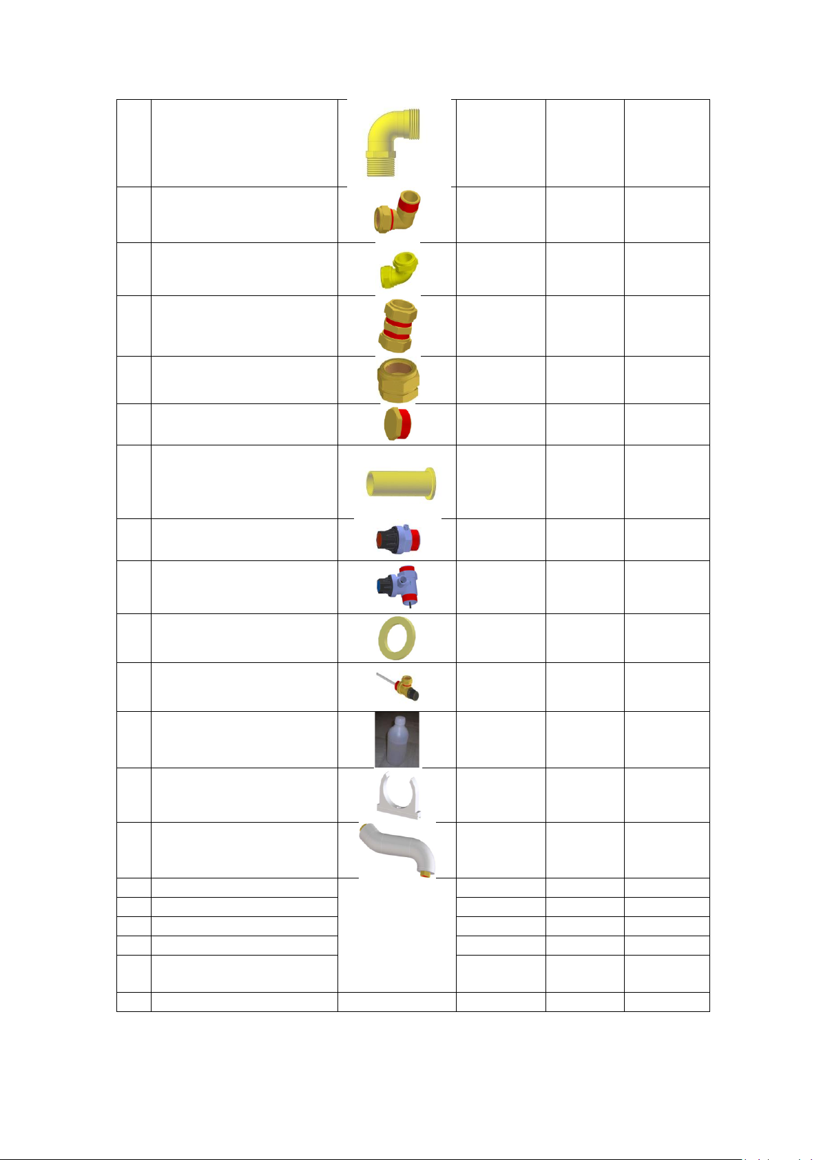
2. The system is containing the following components:
2.1 The solar tank
2.2 The solar collector (s)
2.3 The support base and the installation kit. Detailed information about them is
indicated above.
3. The maximum operation pressure is at 6 bars. In case of higher pressure in the main
it is suggested to use pressure reducer. The closed loop’s maximum operation
pressure is at 3 bars.
4. The maximum temperature of the system is 94C.
5. The system is protected against corrosion, by using 2 Mg anodes. The tank internally
is protected by enamel layer.
6. The used heat transfer fluid is Glycol.
Packaging and transportation
1. The system is packed in a way to ensure the safe transport of its components. For
the tank, there are indication arrows to show the up or down part of the tank in
order to avoid any possible damage. For the collector, there are indication arrows in
order to avoid the damage of the glass.
2. The products must be stored in a protected area against weather conditions. If
necessary to store them outdoors, the packaging of the product must be removed.
Installation guidelines
1. Before install the system make sure that the chosen installation surface can resist
the weight of the system. It must be given a written confirmation by the engineer of
the building that the installation area is proper for this use.
2. In order to make the maintenance of the system easier, the system must be installed
at least 1 m from the walls or the end of the roof.
3. In order to avoid humidity problems or water ingress on the roof, the pipes which
are entering the roof must be very well sealed. The building engineer should provide
you the precise guidelines, depending in the kind of roof construction.
4. All the connection pipes must be very well insulated to avoid freezing or destruction
of them due the UV radiation. Depending on the local weather conditions, it must be
chosen the correct insulation material. For more information contact to the local
dealer.
3
Support base
1. The roof structure must be able to take the wind and snow loads (Note: 1m2 powder
snow ~ 60kg / 1m2 wet snow ~ 200kg).
2. It must be taken under consideration the local conditions regarding snow and wind
loads. Please contact to the local dealer for more information.
Safety equipment
1. On the system exists the safety valve of the closed loop, which is set at 3 bars. This
safety valve must be placed on the top of the tank in one of the 1/2 ‘’ open inlets.
There is also a temperature –pressure valve for the sanitary water. This valve is set
at 94C maximum temperature and 6 bars maximum pressure. This valve must be
placed on the top of the tank on ¾’’ opening.
2. Both above mentioned valves must be connected with the tubes to the disposal
system of the building. In this way will be avoided injuries during the function of the
system.
Starting up the system
1. Cover the collector with a non transparent material. This must be removed after
completing the installation.
2. In order to start filling in the system you have to follow the following guidelines:
1.1 First the tank must be filled in with water from the main supply of the building.
1.2 Secondly it must be filled in the closed loop with the mixture of glycol –water.
1.3 Place all the fittings and make sure that there is no leakage.
3. The system can produce hot water higher than 60C. For this reason it is highly
recommended the use of mixture valve.
Freezing protection
1. The thermal medium should be used for the solar applications is PROPYLENE GLYCOL
1,2 . This thermal fluid is also used to protect the system against freezing.
The thermal fluid must be mixed with water in a percentage that is necessary to
protect the system.
PERCENTAGE %
TEMPERATURE ºC
5
-2
10
-4
15
-5
25
-10
30
-14
35
-17
4
40
-22
50
-32
60
-49
80
-57
ATTENTION: The collectors should remain covered before fill in the thermal fluid.
Troubleshooting
If a reduced efficiency of the solar system is noticed during a sunny day, then check the
following:
The installation is correctly orientated.
Obstacles do not shade the collectors.
The collector’s glass surface is clean from opaque substances.
The collectors are placed correctly on the ground.
The closed circuit does not have any leakage.
The liquid’s level in the closed circuit is not low.
The connections of the closed circuit have to be properly insulated.
Information for the end user
Before starting the system
1. Before starting the system make sure that all the valves and safety devises are
working properly.
2. Make sure that the system is filled in with water.
3. Make sure that the system is filled in with glycol.
4. In case of any failure please contact to the local dealer.
Regular operation of the safety valves
1. The system is equipped with a 3 bars safety valve for the protection of the closed
loop. This valve should be remained open when the internal pressure of the closed
loop is higher than 3 bars.
2. The system is equipped with a temperature-pressure valve. When the temperature
of the sanitary water is exceeding 94C or 6 bars the valve is opening.
Overheating –freezing
1. The system has protection against overheating. In order to avoid it, is recommended
to cover the collectors during the summer period or when the system is going to be
out of function for a long period.
2. The system is protected against freezing by using glycol. The level of glycol must be
checked every year by authorized technician. Depending on the local conditions you
5
must be advised by the local dealer about the lowest freezing temperature that the
system can resist. The used glycol is Propylene Glycol 1,2.
Maintenance
1. The system must be maintenance every year, by authorized technician. The
necessary replacement and processes are:
1.1 Replacing of the Mg anodes
1.2 Checking of the safety valves
1.3 Checking of the level of the glycol in the closed loop. If necessary it must be
filled in with the necessary quantity.
1.4 Checking of the connection tubes between collector and tank.
1.5 Replacing of the sealing gaskets of the tubes if necessary.
Performance of the system
All the systems have been tested in accordance to EN12976 and are Solar Keymark certified.
Your local dealer will provide you all the necessary information regarding the following:
1. The recommended load range for the system in l/day.
2. The thermal performance of the system and solar fraction.
ATTENTION:
The system can reach temperature of 94C. For this reason be extremely careful during
sunny days in order to avoid injuries.
6
Assembly of the support base
Inside the carton box of the support base, you will find all the necessary materials for the
proper assembly of the support base for flat or tiled roof.
Nr.
Description
Photo
SOLECO160 -200 200 300
1
Floor L-bar 2000
2 2
2
2
L - bar 1370
4
4
4
3
L - bar 960
2
2
2
4
L –bar 1030
2
2
2
5
Connections L- bar 360
2
2
2
6
Collector holders 1005
2
-
-
7
Collector holders 2000
-
2
2
8
Z - Part
2
2
2
9
U - Part
2
2
2
10
Back crossbar 1505
2
2
-
11
Back crossbar 1760
-
-
2
12
Bolts M10X16
23
23
23
13
Nut M10
23
23
23
14
Flat washer M10
29
29
29
15
Inox tile holder
4
4
4
16
Bolts M8X12
4
8
8
17
Bolts M8X20
1
1
1
18
Flat washer M8
4
8
8
19
Front cover 1030
1
-
-
20
Front cover 1250
-
1
-
21
Front cover 1750
-
-
1
22
Anchor bolt M8X50
4
4
4
23
PLASTIC ANCHORS
4
4
4
220 2.5
7
24
ELBOW ¾MALE-FEMALE
2
2
2
25
ELBOW 22MM X¾MALE
2
2
2
26
ELBOW 22mm x 22mm
1
1
1
27
22MM X 22MM CONNECTOR
-
2
2
28
PLUG 22MM
2
2
2
29
PLUG 1/2MM
1
1
1
30
SLEEVE D22
4
8
8
31
SAFETY VALVE 3BARS
1
1
1
32
SAFETY VALVE 6BARS
1
1
1
33
SEALING RINGS
4
4
4
34
TEMPERATURE-PRESSURE
VALVE 94C-6BARS
OPTIONAL
OPTIONAL
OPTIONAL
35
GLYCOL
2
3
4
36
SIDE TUBE HOLDER
1
1
1
37
INSULATED TUBE 320mm
1
-
-
38
INSULATED TUBE 650mm
-
-
1
39
INSULATED TUBE 210mm
1
-
-
40
INSULATED TUBE 800mm
-
1
1
41
INSULATED TUBE 900mm
-
1
-
42
INSULATED COPPER TUBE
Ǿ22 x2000mm
1
1
1
43
8
Installation of the system on a flat roof
ATTENTION:
For the flat roof assembly the inox tile holders are not used!!!
Lay on the ground the
2 Floor L-Bar 2000 in
parallel. The distance
between them should
be at 940 mm for the
models Soleco 160-200 2.5
and 200/2. For the
model Soleco 300 it should
be at 1350mm.
Left side Floor
L-bar 2000
Right side
Floor L-bar
2000
9
Fix the L - bar 1370 to
the 2nd hole of the
Floor L-Bar 2000. This
is the same for all
models.
Use the connection
Connections L- bar 360
in order to bind L -bar
1030 with L - bar 1370.
Then use screw + nut
to tighten the
connection.
ATTENTION: Do not
tight very well at that
stage of the assembly.
Fix the joined parts of
the previous step at
the 2nd hole of Floor
L-bar 2000
2nd hole
10
Fix the joined parts of
the previous step with
the L - bar 1370. It
must be fixed on the
3rd hole.
Join the back
crossbars together by
fixing them in the
middle with bolt and
nut. The upper parts
must be fixed on the
2nd hole and the lower
part on the 3rd hole of
L - bars 1370.
3rd hole