unicraft EWH Series User manual

EHW 15
Instruction Manual
Electric lift truck
EHW 12
EHW 15
EHW 20

2EHW-Series | Version 1.02
Imprint
Product identification
Electric lift truck Item number
EHW 12 6160112
EHW 15 6160115
EHW 20 6160120
Manufacturer
Stürmer Maschinen GmbH
Dr.-Robert-Pfleger-Str. 26
D-96103 Hallstadt
Fax: 0049 (0) 951 96555 - 55
E-Mail: [email protected]
Internet: www.unicraft.de
Information on the operating instructions
Original operating instructions
Edition: 30.03.2020
Version: 1.02
Language: English
Author: ES/FL
Copyright information
Copyright © 2020 Stürmer Maschinen GmbH, Hallstadt,
Germany.
The contents of these operating instructions are the sole
property of the Stürmer company. Passing on and repro-
duction of this document, exploitation and communica-
tion of its contents are prohibited unless expressly per-
mitted. Contraventions obligate the user to pay
damages.
Technical changes and errors excepted.
Contents
1 Introduction ..............................................3
1.1 Copyright ............................................................ 3
1.2 Customer service................................................ 3
1.3 Disclaimer........................................................... 3
2 Safety ........................................................3
2.1 Legend of symbols.............................................. 3
2.2 Operator responsibility........................................ 4
2.3 Operating staff qualification ................................ 5
2.4 Personal protective equipment ........................... 5
2.5 Safety identifications on the device .................... 5
2.6 General safety instruction ................................... 6
2.7 Inspections and Approvals.................................. 6
3 Intended Use ............................................6
3.1 Foreseeable misuse ........................................... 6
3.2 Residual risks ..................................................... 6
4 Technical Data..........................................7
4.1 Type plate ........................................................... 7
5 Transport, packaging, storage................7
5.1 Transport ............................................................ 7
5.2 Packaging........................................................... 8
5.3 Storage ............................................................... 8
6 Description of the device ........................8
7 Commissioning ........................................8
7.1 Operating conditions........................................... 8
7.2 Operation............................................................ 9
7.3 Pin-Code-Display.............................................. 10
7.4 Errors................................................................ 11
7.5 Emergency........................................................ 11
8 Care, Maintenance and Repair..............11
8.1 Care by cleaning............................................... 11
8.2 Maintenance and repair.................................... 11
8.3 Charging socket................................................ 14
8.4 Maintenance intervals....................................... 14
8.5 Troubleshooting................................................ 15
8.6 Error code ......................................................... 16
9 Disposal, Reusing used Machines .......21
9.1 Decommissioning ............................................. 21
9.2 Disposal of electrical equipment....................... 21
9.3 Disposal via municipal collection points............ 21
9.4 Disposal of lubricants........................................ 21
10 Spare parts ...........................................22
10.1 Ordering spare parts....................................... 22
10.2 Spare parts drawing........................................ 23
11 Circuit diagrams...................................44
11.1 Wiring EHW 12, EHW 15 and EHW 20 .......... 44
11.2 Circuit diagrams EHW 12 ............................... 45
11.3 Electrical diagrams EHW 15 and EHW 20...... 47
12 EC-Declaration of Conformity.............49

Introduction
EHW-Series | Version 1.02 3
1 Introduction
You have made an excellent choice in purchasing a
UNICRAFT Electric lift truck.
Carefully read the operating instructions prior to
commissioning.
They describe correct commissioning, intended use and
safe as well as efficient operation and maintenance of
your Electric lift truck.
The operating instructions form part of the Electric lift
truck. Keep these operating instructions at the installa-
tion location of your Electric lift truck. Please also note
the locally applicable accident prevention regulations
and general safety regulations for the use of Electric lift
truck. Illustrations in these operating instructions serve
the basic understanding and can deviate from the actual
design.
1.1 Copyright
The contents of these operating instructions are pro-
tected by copyright. Their application is permitted within
the context of the use of the Electric lift truck. Any further
use shall not be permitted without written consent by
Stürmer GmbH. For the protection of our products, we
shall register trademark, patent and design rights, as this
is possible in individual cases. We strongly oppose any
infringement of our intellectual property.
1.2 Customer service
Please contact your specialist retailer if you have any
questions regarding your Electric lift truck or require any
technical information. Your specialist retailer will be happy
to support you with specialist advice and information.
Germany:
Stürmer Maschinen GmbH
Dr.-Robert-Pfleger-Str. 26
D-96103 Hallstadt
Germany
Repair service:
Hotline: 0049 (0) 900 19 68 220
(0.49 Euro from German landlines)
Fax: 0049 (0) 951 96555-111
Email: service@stuermer-maschinen.de
Spare parts orders:
Fax: 0049 (0) 951 - 96555-119
Email: ersatzteile@stuermer-maschinen.de
Please submit any information and experiences you
make during application of the machine as these may be
valuable for product improvements.
1.3 Disclaimer
All data in these operating instructions has been com-
piled on the basis of the state-of-the-art, valid standards
and guidelines as well as our many years of expertise
and experience.
The manufacturer shall not be liable for damage in the
following cases:
- Non-observance of these operating instructions
- Unintended use
- Deployment of untrained staff
- Conversions at one's own responsibility
- Technical modifications
- Use of unauthorised spare parts
The actual scope of delivery may deviate from the de-
scriptions and illustrations in this document as a result of
special variants, optional extras or recent, technical
modifications.
The obligations defined in the supply contract shall apply
in addition to the general terms and conditions and the
manufacturer's general terms and conditions as well as
the statutory regulations valid at the time of the conclu-
sion of the contract.
2 Safety
This section provides an overview of all important safety
packages for personal protection as well as safe and reli-
able operation. The sections on individual service life
phases contain additional, specifically applicable safety
information.
2.1 Legend of symbols
Safety instructions
Safety instructions in these operating instructions have
been highlighted with symbols. Safety instructions are in-
dicated by signal terms that express the degree of risk
involved..
DANGER!
This combination of symbol and signal term indi-
cates a directly dangerous situation which may
cause death or serious injury if not averted.
WARNING!
This combination of symbol and signal term indi-
cates potentially hazardous situations which may
cause death or serious injury if not averted.

4EHW-Series | Version 1.02
Safety
Tips and recommendations
Observe the safety information in these operating in-
structions to minimise the risk of personal injury as well
as material damage and prevent hazardous situations.
2.2 Operator responsibility
Operators are defined as the persons who operate the
machine for commercial or profit-based purposes or pro-
vide the machine to third parties for use or application
and bear the legal product responsibility in terms of the
protection of users, staff or third parties during operation.
Obligations of the operator:
If the machine is used for commercial purposes, opera-
tors are subject to the legal stipulations in terms of occu-
pational safety. For this reason, the safety instructions in
these operating instructions as well as the safety, acci-
dent prevention and environmental protection regula-
tions valid at the installation location must be complied
with. In this process, the following shall apply in particu-
lar:
- Operators shall obtain information about valid oc-
cupational safety regulations and determine addi-
tional hazards as part of a risk assessment which
result from the specific operating conditions at the
machine's installation location. Said risk assess-
ment shall be reflected in operating instructions for
machine operation.
- During the entire machine operating time operators
must check whether the operating instructions they
created meet current standards and adapt the op-
erating instructions where necessary.
- Operators shall clearly manage and specify the re-
sponsibilities for installation, operation, trouble-
shooting, maintenance and cleaning.
- Operators must make sure that all persons han-
dling the machine have read and understood these
operating instructions. Operators must also regu-
larly train staff and notify of the hazards.
- Operators shall provide staff with the required pro-
tective equipment and wearing the required protec-
tive equipment shall be mandatory.
Operators shall also be responsible for maintaining the
machine in a technically perfect condition. For this rea-
son, the following shall apply:
- Operators shall make sure that the maintenance in-
tervals described in these operating instructions
are complied with.
- Operators shall regularly check that the safety
equipment is fully functional and complete.
CAUTION!
This combination of symbol and signal term indi-
cates a potentially hazardous situation which may
cause minor or light injuries if it is not averted.
ATTENTION!
This combination of symbol and signal term indi-
cates a potentially dangerous situation which may
cause material damage or harm the environment if it
is not averted.
NOTE!
This combination of symbol and signal term indicates
a potentially dangerous situation which may cause
material damage or harm the environment if it is not
averted.
Tips and recommendations
This symbol highlights useful tips and recommenda-
tions as well as information for efficient and reliable
operation.

Safety
EHW-Series | Version 1.02 5
2.3 Operating staff qualification
The different tasks described in these operating instruc-
tions require different levels of skills in terms of the quali-
fications of operating staff working with the machine.
Exclusively persons of whom it can be expected that
they reliably complete assigned tasks shall be author-
ised to carry out any tasks. Persons whose reactions
have been impaired shall not be authorized, e.g. drug us-
ers, users under the influence of alcohol or medication.
These operating instructions specify the following per-
sonal qualifications for the different tasks:
Operating staff:
Operating staff has undergone an induction by the oper-
ator about the entrusted tasks and potential hazards re-
sulting from improper behaviour. Operating staff shall ex-
clusively be permitted to carry out any tasks beyond
operation in normal mode if this has been specified in the
operating instructions and operators have explicitly en-
trusted operating staff with the task.
Specialist staff:
As a result of specialist training, expertise, experience
and skills in terms of the relevant standards and regula-
tions, specialist staff is able to complete the tasks they
are entrusted with and independently identify hazards
and avert risks.
Manufacturer:
Certain work must be carried out by manufacturer spe-
cialist staff only. Other staff is not permitted to carry out
this work. Contact our customer service to have the work
carried out.
2.4 Personal protective equipment
Personal protective equipment is intended to protect the
health and safety of persons at work. Staff must wear the
personal protective equipment indicated in individual
sections of these operating instructions when carrying
out the different tasks on the machine.
The personal protective equipment is described in the
following section:
2.5 Safety identifications on the device
The following safety identifications have been attached
to the device (Fig. 1) which must be observed.
Fig. 1: Safety labels
Safety identifications attached to the machine must not
be removed. Damaged or missing safety identifications
may cause errors, personal injury and material damage.
They must be replaced immediately.If the safety identifi-
cations are not visible and comprehensible at first
glance, the machine must be stopped until new safety
identifications have been attached.
WARNING!
Risk from inadequately qualified
persons!
Inadequately qualified persons are unable to assess
the risks when handling the device, thus putting
themselves and others at risk of severe or fatal inju-
ries.
- All work must be carried out by qualified persons
only.
- Keep inadequately qualified persons away from the
work area.
Head protection
The industrial helmet protects the head against fal-
ling objects and bumping into stationary objects.
Protective gloves
Protective gloves are intended to protect the hands
from components with sharp objects as well as fric-
tion, abrasion, and deep-cut injuries.
Safety shoes
Safety shoes protect feet from pinching, falling parts
and slipping on slippery surfaces.
Protective clothing
Protective clothing is tight-fitting work clothing without
protruding parts, usually with a low tear resistance.

6EHW-Series | Version 1.02
Intended Use
2.6 General safety instruction
The valid accident prevention regulations must be follo-
wed. If the Electric lift truck is intended for use by em-
ployees, the relevant labour law regulations must also be
observed, e.g. accident prevention regulation VBG 36.
The surface on which the Electric lift truck stands and on
which it is moved must be sufficiently stable, firm and le-
vel.
2.7 Inspections and Approvals
According to VBG 36 (BGV D27), the lift truck must be
inspected by an expert as required, but at least once a
year.
3 Intended Use
The electric pallet truck is an electrically operated con-
veyor and is designed for lifting, lowering and transpor-
ting palletized loads on level and paved roads up to the
specified maximum load. The lift truck is designed for the
unit load transport of standardized pallets, grid boxes
and other palletized loads in internal traffic. The lift truck
must not be used in rooms with explosion hazards or en-
vironments with aggressive materials.
The electric lift truck may only be operated by instructed
persons. It must be in technically perfect condition. Pos-
sible damages or malfunctions must be eliminated im-
mediately.
Proper use also includes compliance with all information
in this manual. Any use beyond the intended use or any
other use is considered as misuse.
The company Stürmer Maschinen GmbH does not ac-
cept any liability for design and technical modifications to
the electric lift truck.
Claims of any kind for damage due to improper use are
excluded.
3.1 Foreseeable misuse
If the electric pallet truck is used as intended, no reaso-
nably foreseeable misuse is possible which could lead to
dangerous situations with personal injury.
3.2 Residual risks
Even if all safety regulations are observed, a residual risk
remains when operating the electric lift truck as descri-
bed below. All persons working with the electric pallet
truck must be aware of these residual risks and follow
the instructions to prevent these residual risks from cau-
sing accidents or damage.
During operation there is a risk of crushing the lower
limbs.
During setup and set-up work it may be necessary to re-
move protective devices provided by the customer. This
results in various residual risks and potential dangers,
which every operator must be aware of.
NOTE!
The improper use (misuse) of the electric lift truck as
well as the disregard of the safety regulations or the
operating instructions exclude any liability of the
manufacturer for resulting damages to persons or
objects and cause the warranty claim to expire!
WARNING!
The Electric lift truck is not intended for the transport
of persons. It is also forbidden to sit on the device
and drive it.

Technical Data
EHW-Series | Version 1.02 7
4 Technical Data 4.1 Type plate
Fig. 2: Type plate EHW 12
5 Transport, packaging, storage
5.1 Transport
Check the electric lift truck after delivery for visible trans-
port damage. If you discover any damage, report it im-
mediately to the transport company or the dealer.
Transport with a crane:
Attach the lift truck according to the points shown in Fig.
3. Lift the lift truck and bring it to its destination. Park the
lift truck safely before removing the hoist.
Fig. 3: Transport with a crane
EHW 12 EHW 15 EHW 20
Dimensions
(LxWxH) ca.
1537 x
540 x
700 mm
1530 x
540 x
700 mm
1536 x
540 x
540 mm
Weight 124 kg 123 kg 149 kg
Load-bearing
capacity
1,2 T 1,5 T 2,0 T
Load-bearing
width
540 mm 540 mm 540 mm
Fork width 160 mm 160 mm 160 mm
Fork length 1150 mm 1150 mm 1150 mm
Chassis
height
628 mm 628 mm 628 mm
Lifting range 80 - 195 mm
Lifting speed 0,031
m/s
0,02
m/s
0,017
m/s
Lowering
speed
0,069 m/s 0,05 m/s 0,05 m/s
Turningradius 1337 mm 1330 mm 1336 mm
Swivel ca-
stors Ø
210 mm 210 mm 210 mm
Castor width 70 mm 70 mm 70 mm
Steering rol-
lers Ø
80 mm 80 mm 80 mm
Load rollers
width
93 mm 93 mm 93 mm
Load rollers
material
PU PU PU
Lifting motor
power [kW]
0,5 bei
S3 10%
0,5 bei
S3 10%
0,8 bei
S3 10%
Battery
voltage
24 V 24 V 48 V
Battery capa-
city
20 Ah 20 Ah 20 Ah
Battery weight 4,4 kg 4,6 kg 7,5 kg
Travel speed 4,6 km/h 4,6 km/h 4,8 km/h
Drive motor
power [kW]
0,65 bei
S2 60
min
0,65 bei
S2 60 min
0,75 bei
S2 60
min
Sound pres-
sure level
70 dB 70 dB 70 dB
Max. Load
gradient
4° 6° 7°
Max. Slope un-
loaded
16° 16° 16°
NOTE!
Protect the electric lift truck from moisture.
DANGER!
Danger to life by falling of the load!
Note the attachment points in Figure 3!

8EHW-Series | Version 1.02
Description of the device
Transport on a truck:
Lower the forks and place the lift truck securely on the
truck carrier surface. Attach the lift truck as shown in Fig.
4 by inserting special fastening straps into the wheel ho-
les on the fork of the electric lift truck and fasten the other
side of the strap to the truck.
Fig. 4: Transport on a truck
5.2 Packaging
All packaging materials and packaging aids used are
recyclable and must always be recycled.
Shredded cardboard packaging components should be
disposed of in the waste paper collection.
The foils are made of polyethylene (PE), the padded
parts of polystyrene (PS). These materials can be han-
ded in at a recycling collection point or to your local wa-
ste disposal company.
5.3 Storage
To store the electric lift truck, remove the load, lower the
fork to the lowest position, grease all lubrication points
and then protect from corrosion and dust.
6 Description of the device
Figures in these operating instructions may deviate
from the original.
Fig. 5: Description of the device
1 Safety button
2 Drawbar
3 LED charge status display
4 Key switch
5 Emergency stop switch
6 Cover of the hydraulic unit
7 Chassis
8 Fork
9 Load roller
10 Battery
11 Apron
12 Drive unit
13 Side roll (option)
7 Commissioning
7.1 Operating conditions
The work area must be fire and explosion proof and free
of corrosive and toxic substances.
Dangerous goods such as flammable, toxic or radioac-
tive materials must not be lifted and transported with the
electric lift truck.
The electric lift truck is intended for indoor use with ambi-
ent temperatures between +5°C and +40°C.
The working lighting must be at least 50 lux.
DANGER!
- Only use cranes and hoists that are designed for
this purpose.
- Do not stand under the load!
- Always secure the lift truck securely during trans-
port!
NOTE!
Only store the lift truck with the fork lowered! Do not
place anything on the electric pallet truck.

Commissioning
EHW-Series | Version 1.02 9
7.2 Operation
Check before operating the lift truck:
- Visual inspection of the lift truck for damage, especi-
ally of the tiller, operating lever, chassis, fork,
wheels,
- Visual inspection for oil leaks,
- Testing the lifting and lowering mechanism without
load,
- Testing for cleanliness and smooth running of the
wheels,
- Check for tightness of all screws and nuts,
- Check for the presence and legibility of all security
marks.
7.2.1Lifting and transporting loads
Fig. 6: Correct position of the load (example image)
Fig. 7: Operation
Step 1: Turn the emergency stop switch (item 5, Fig. 5)
clockwise and insert the key (item 4, Fig. 5).
Step 2: Press the horn button (item 15, Fig. 7) to activate
the acoustic warning signal.
Step 3: Drive with the lowered forks completely under the
pallet and press the lift button (item 16, fig. 7)
until you have reached the desired lifting
height.
Step 4: Move the load to the desired location.
Step 5: After you have started the electric lift truck by in-
serting the key, move the tiller to the working
zone ("F", Fig. 8). Turn the gas handle in the
desired direction forwards "Fw." or backwards
"Bw. (Fig. 8).
Fig. 8: Drive forward/backward
Step 6: Control the speed by carefully moving the gas
button (item 14, fig. 7) until you reach the desi-
red speed. When you move the gas button
back to the neutral position, the control unit will
decelerate the lift truck until the lift truck stops.
When the electric pallet truck has stopped, the
parking brake is applied.
Step 7: Drive carefully to your destination. Observe the
track conditions and adjust the speed with the
throttle button.
DANGER!
Before using the electric lift truck, please read the
chapter "Safety.
Wear protective gloves!
Wear safety shoes!
Wear protective clothing!
CAUTION!
Risk of crushing!
There is a risk of injury to fingers and hands when
working improperly on the electric lift truck. DANGER!
On inclines, only drive with the load upwards.
Do not drive on gradients exceeding the specified
values (max. gradeability: 4% loaded/ 16% unloa-
ded).

10 EHW-Series | Version 1.02
Commissioning
Press the Turtle button (item 18, fig.7) to switch
to slow speed mode. Drive slowly by moving
the gas button (item 14, fig.7), press the turtle
button again to return to normal mode.
Press and hold the Turtle button for 2 seconds
to activate the drive function with tiller in vertical
position when working in confined spaces. The
drive function is only active when the turtle but-
ton is pressed (speed is reduced); releasing the
turtle button stops immediately. Activating the
gas button in less than two seconds after the
turtle button is pressed will not activate the
drive function, but will repeat the operation cy-
cle from the beginning. The gas pedal button
should remain in the neutral position for two se-
conds.
The electric lift truck is controlled by moving the
tiller to the left or right
Step 8: Press the lowering button (item 17, Fig. 7) care-
fully. Lower the load until the forks are free of
the pallet and then carefully drive the lift truck
out.
7.2.2Brake function
The brake function can be activated in various ways:
1. The regenerative braking is activated by pushing the
gas button (item 14, Fig. 7) to the initial position "0" or
by releasing the button. The lift truck brakes to a
standstill.
2. By moving the accelerator pedal (pos. 14, Fig. 7) from
one direction of travel directly in the opposite direction,
the vehicle brakes until it moves in the opposite direc-
tion.
3. The electric lift truck brakes when the tiller is moved
up or down in the braking zones ("B"). When the tiller
is released, the tiller automatically moves into the up-
per baking zone ("B") and the electric lift truck brakes
to the stop.
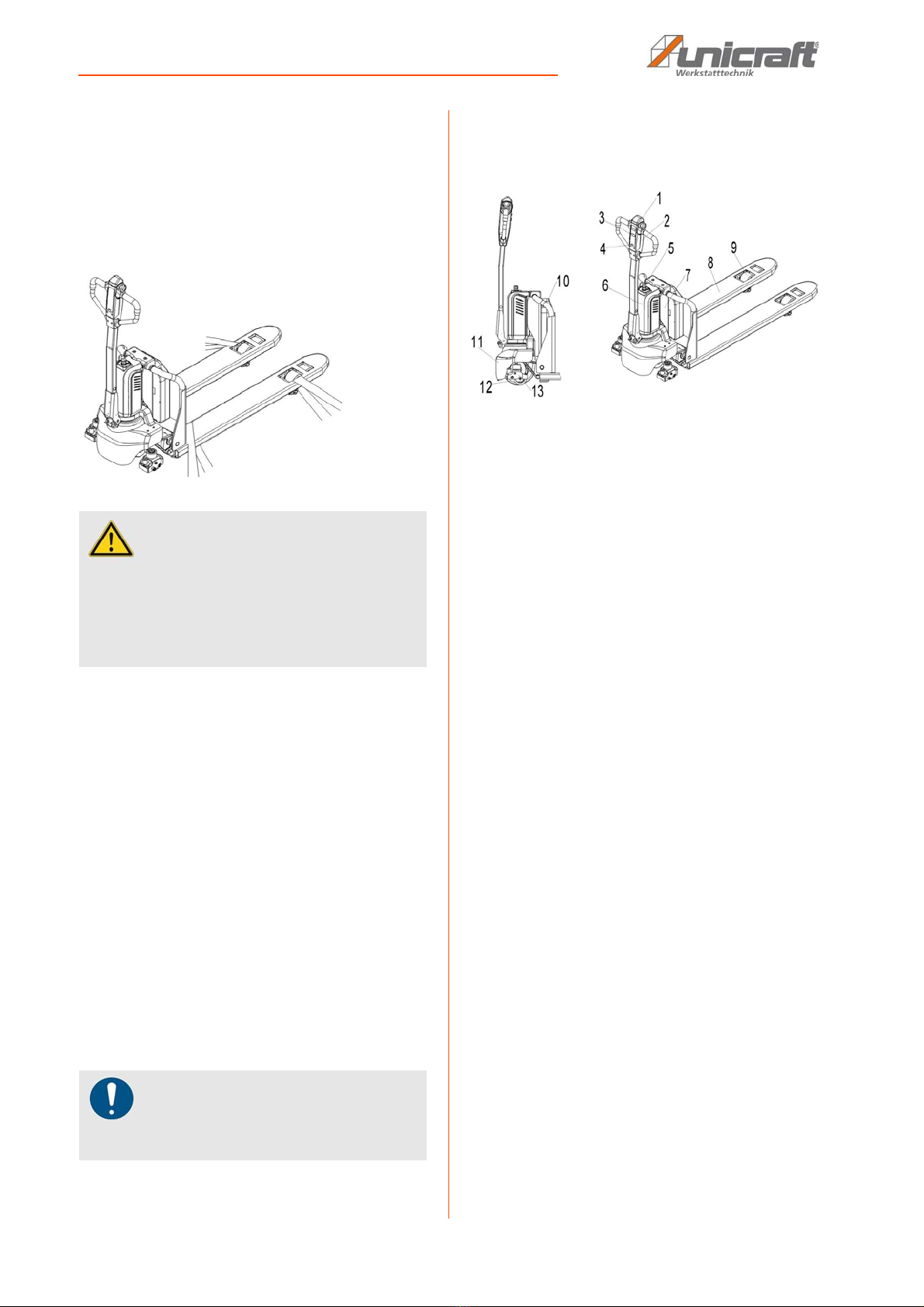
4. The safety button (pos. 1, fig. 5) prevents the operator
from being squeezed. When this button is activated,
the vehicle decelerates and/or begins to travel in re-
verse ('Bw.') for a short distance and stops. Please
note that this button also works when the vehicle is not
moving and the tiller is in the working area.
7.3 Pin-Code-Display
The electric pallet truck EHW 15 is
equipped with a pin code control panel
(3). It can only be operated if the cor-
rect password is entered.
The electric lift truck EHW 20 is equip-
ped with a pin code control panel (3)
and ID cards. It can only be operated if
the correct password is entered or a valid ID card is
used.
The pin code control panel is an electronic system simi-
lar to an electronic alarm system. The lift truck can only
be operated after a correct password has been entered.
The main function is to prevent unauthorized operation.
Main functions
The Pin Code Control has two passwords, one is the de-
fault user password 1234, which you can use immedi-
ately.
The other is the administrator password 3232, which
allows you to set a new user password according to the
steps below:
Step 1: Enter "3232", click on "√".
Step 2: Enter the previous user password, click on "√".
Step 3: Enter a new password and click on "√", the pre-
vious password will be replaced.
If you want to reset the password, please proceed as de-
scribed below:
Step 1: Enter "123", click on "√".
Step 2: Enter "123" again, click on "√". The password is
now "1234".
If you need to add more ID cards (EHW 20 only), please
proceed as follows
Step 1: Enter "3434", click on "√".
Step 2: Insert the new ID card for about 5 seconds.
DANGER!
The electric pallet truck is equipped with an electro-
magnetic, fail-safe holding and parking brake.
Always lower the forks completely. Press the emer-
gency stop switch (pos. 5, fig. 5).
Do not park the lift truck on inclined surfaces.
NOTE!
- Please determine the braking distance of the
electric lift truck before starting up.
- The braking power depends on the track conditions
and the load conditions of the lift truck.
NOTE!
The pin code control panel supports a maximum of
five cards.

Care, Maintenance and Repair
EHW-Series | Version 1.02 11
7.4 Errors
In case of malfunction or failure of the electric lift truck,
please stop the lift truck and activate the emergency stop
switch (pos. 5, fig. 5) by pressing it. If possible, park the
lift truck in a safe place and remove the key (pos. 4, fig.
5).
Call the customer service department. If necessary, pull
the lift truck out of the working area using special pulling/
lifting devices.
7.5 Emergency
Keep a safe distance immediately in case of an emer-
gency or if you fall over (or crash). If possible, press the
emergency stop switch (item 5, Fig. 5). All electrical func-
tions are stopped.
8 Care, Maintenance and Repair
8.1 Care by cleaning
The Electric lift truck must always be kept in a clean con-
dition.
All plastic and lacquered surfaces should be cleaned a
soft, damp cloth and a neutral cleaning agent.
Remove any excess lubricant or leaked oil using a dry,
lint-free cloth.
8.2 Maintenance and repair
If the electric pallet truck does not function properly, con-
tact a dealer or our customer service department. The
contact details can be found in chapter 1.2 Customer
Service.
All protective and safety devices must be reinstalled im-
mediately after repair and maintenance work has been
completed.
Regular maintenance:
- After each use, unload the lift truck and lower the
fork to the lowest position.
- Check the pallet truck for oil leaks and external da-
mage, especially to the wheels and axles, before
each use.
- If necessary, lubricate all moving parts of the pallet
truck with high quality grease.
- Check all screws and nuts for tightness.
- Check the lifting and lowering mechanism for proper
function.
- Make sure that all safety instructions on the pallet
truck are clearly legible.
- The pressure valve may only be adjusted by trained
service technicians.
- Check the smooth running of the wheels.
- Check the driving function in both directions.
- Check the brake function.
- Check the function of driving with the tiller in vertical
position.
- Check the function of the emergency brake by ope-
rating the emergency stop switch.
- Check the function of the steering by turning the tiller
from one end position to the other. The steering
should be easy to move, without shocks or distur-
bing noises.
Tips and recommendations
To ensure that den Elektro-Hubwagen is always in
good working order, regular care and maintenance
work must be carried out.
Use protective gloves!
NOTE!
Never use strong cleaning agents to clean the device.
Such cleaning agent might damage or destroy the de-
vice.
DANGER!
Maintenance and repair work may only be carried out
by instructed persons.
Repairs may only be carried out by specialists!
Only use original spare parts.

12 EHW-Series | Version 1.02
Care, Maintenance and Repair
8.2.1Battery
Exchange
Park the carriage safely and press the emergency stop
switch (item 5, Fig. 5). Hold the battery handle with one
finger, pull the lock out and then remove the battery verti-
cally. Installation is in reverse order.
Turtle symbol:
It is normally turned off; when it is dis-
played, it indicates the activation of the electric pallet
truck's "soft" mode, in which the maximum speed and
acceleration are reduced.
Wrench symbol (only for EHW 15 and
EHW 20):
It is normally off, when the icon appears it indicates the
request for scheduled maintenance or the alarm condi-
tion. In this case, the corresponding code is displayed.
The information provided can be very useful. Malfuncti-
ons can be quickly identified by the operator or service
technician, allowing the problem to be solved quickly.
Hourglass symbol (only for EHW 15 and EHW 20):
It flashes when the hour counter is in operation.
Battery indicator:
EHW 12:
The charge status of the
battery is indicated by
four LEDs on the tiller:
The first green LED from the left lights up and indicates
75% -100% of the battery charge.
The second blue LED from the left is on and indicates
50% -75% of the battery charge.
The third yellow LED from the left is on and indicates
25% -50% of the battery charge.
The fourth LED from the left is lit and indicates 0% -25%
of the battery charge.
If there is an error, four LEDs flash for 1s, then the first
green LED from the left flashes and is counted, then the
fourth LED from the left flashes and is counted. The
quantity that the green LED blinks times ten times, then
plus the quantity that the LED blinks means the error
code.
EHW 15 and EHW 20:
Fig. 9: Display
An alphanumeric liquid crystal display is located in the
center of the unit, showing the hours worked. The display
is backlit.
The display indicates the alarm status and displays a
code corresponding to the type of alarm.
The battery charge level is indicated by ten levels. Each
level corresponds to 10% of the battery charge. When
the battery is being discharged, the stages switch off one
after the other in stages in relation to the value of the re-
maining battery charge.
EHW 15: If the error code 0 appears on the display, it
means that the battery voltage is low. The lifting
function is interrupted. Error code 91 appears
when the vehicle is used without charging, the
driving speed is slowed down.
EHW 20: If error code 12 appears on the display, it me-
ans that the battery voltage is low. The lifting
function is interrupted. Error code 91 appears if
the vehicle continues to be used without
recharging, the driving speed will slow down.
Recharge
- Before charging, make sure that you are using a
suitable charger to charge the built-in battery.
- Before using the charger, please read the instructi-
ons in the charger manual completely.
- Always follow these instructions.
DANGER!
- Only qualified personnel may service or charge the
batteries. The batteries are lithium batteries.
- Recycling of batteries is subject to national regulati-
ons. Please observe these regulations.
- Open fire is prohibited when using batteries!
- Neither burning materials nor burning liquids are
allowed in the battery charging area. Smoking is
prohibited and the area must be ventilated.
- Park the vehicle safely before starting to charge or
install/change the batteries.
- Before completing maintenance, ensure that all ca-
bles are connected correctly and that there is no in-
terference with other components of the vehicle.
- Only lithium batteries may be used. Please observe
the maximum operating temperature of the batte-
ries.
Akku empty:
Battery is charged:

Care, Maintenance and Repair
EHW-Series | Version 1.02 13
- The room where you are charging must be ventilated
by ventilation.
- The exact charge level can only be checked at the
discharge door. To check the status, the charge
must be interrupted and the electric pallet truck star-
ted.
Step 1: Park the lift truck in a designated secure area
with an appropriate power supply.
Step 2: Lower the forks and remove the load;
Step 3: Switch off the electric pallet truck and connect
the charging plug (pos. 20, fig. 10) to the char-
ging opening (pos. 21, fig. 10) of the battery.
The charger starts charging the battery when
the charging plug (pos. 19, fig. 10) is
connected to the mains.
Step 4: Remove the charger plug from the battery and
close the cap after the charger has finished
charging.
Step 5: When the charging process is finished, pull the
plug (item 19, Fig. 10) out of the socket and
put it into the designated bag.
Fig. 10: Recharge
LED Status:
RED: Charging
GREEN: Fully charged
8.2.2Lubrication points
Smear the marked areas. The required grease specifica-
tion is: DIN 51825, standard grease.
Fig. 11: Lubrication points
8.2.3Check/refill hydraulic oil
The use of hydraulic oil in conjunction with the average
temperature:
NOTE!
It is also allowed to remove the battery and charge it in
a special area.
Ambient tempera-
ture
-5°C ~
25°C
> 25°C
Type HVLP 32
DIN 51524
HLP 46
DIN 51524
Viscosity 28,8 - 35,2 41,4 - 47
Quantity 0,4 L
WARNING!
Waste materials such as oil, used batteries or similar
must be disposed of and recycled in accordance with
national regulations and, if necessary, taken to a
recycling company.
DANGER!
The oil level in the oil reservoir should be between
the min and max marks when the forks are fully lowe-
red. Top up oil at the filling point if necessary.
Lubrication points

14 EHW-Series | Version 1.02
Care, Maintenance and Repair
8.2.4Check the electrical fuses
Remove the main cover. The fuses are arranged as
shown in Fig. 12.
Fig. 12: Check the electrical fuses
FU 1: 10 A
FU 01: 70 A
8.3 Charging socket
Fig. 13: Charging socket
8.4 Maintenance intervals
EHW 12 and EHW 15
EHW 20
I n t e r v a l
(Month)
1 3 6 12
Hydraulic
Check the hydraulic cylinder(s), the
piston for damage noises and leaks.
x
Check the hydraulic connections for
damage and leaks.
x
Check the hydraulic oil level, top up
if necessary.
x
Refill hydraulic oil (12 months or
1500 operating hours)
x
Check and adjust the function of the
pressure valve (0+10%)
x
Mechanical system
Check for deformation and cracks x
Check the chassis for deformation
and cracks.
x
Check that all screws are tight. x
Check the push rods for deformation
and damage.
x
Check gearbox for unusual noises
and noises.
x
Check the wheels for deformation
and damage.
x
Check and lubricate the headset
bearing if necessary.
x
Check and lubricate the pivot points
if necessary.
x
Lubricate grease nipple x
Electrical system
Check electrical wiring for damage. x
Check electrical connections and
terminals.
x
Check function of emergency stop
switch
x
Check the drive motor for noises
and damage.
x
Test the display. x
Check that the correct fuses are
used.
x

Care, Maintenance and Repair
EHW-Series | Version 1.02 15
8.5 Troubleshooting
If the operating results are not satisfactory, check the
following points before systematic checks and before no-
tifying the service center:
Test the warning signal. x
Check the contactor(s). x
Checking the frame leakage (insula-
tion test)
x
Check function and mechanical
wear of the accelerator pedal.
x
Check the electrical system of the
drive motor.
x
Brake system: Check brake power,
replace brake disc if necessary or
adjust air gap.
x
Battery
Check battery voltage x
Clean and grease the clamps and
check for corrosion and damage.
x
Check the battery housing for da-
mage.
x
Charger
Check the main power cable for da-
mage.
x
Check the start-up protection during
the charging process.
x
Functionality
Check the horn function. x
Check air gap of electromagnetic
brake
x
Emergency braking test x
Check reverse gear and regenera-
tive braking.
x
Check safety button function x
Check steering function x
Check the lifting and lowering func-
tion.
x
Check function of drawbar switch x
General information
Check that all stickers are legible
and complete.
x
Check rollers, adjust or replace
height
x
Perform a test run x
I n t e r v a l
(Month)
1 3 6 12
Fault Possible cause Solution
The load cannot be lifted.
1. Load too high
2. Battery low
3. Malfunction of
the lifting
contactor
4. Hydraulic oil
level too low
5. Oil leakage
1. Lift only the maxi-
mum capacity indi-
cated on the name-
plate.
2. charge the battery.
3 Check and, if neces-
sary, contact custo-
mer service for re-
placement.
4 Check the hydraulic
oil and top up if
necessary.
5. repair the cylinder
seal

16 EHW-Series | Version 1.02
Care, Maintenance and Repair
8.6 Error code
EHW 15
Code Description Possible cause Part
0 LOW POWER Battery low Control sy-
stem
1 PUMP ERROR The switch for lifting or lowering was activated earlier than the key
switch
Control sy-
stem
2 SRO ERROR Operating sequence of direction, locking and key switch is not cor-
rect.
Control sy-
stem
3 HPD-ERROR The function sequence of the interlock and accelerator pedal is not
correct; or the accelerator pedal is not returned to the neutral position
after the EMERGENCY STOP SWITCH has been operated.
Control sy-
stem
4
MAINTENANCE FAI-
LURE
Speed regulator:
1. Adjusted accelerator pedal.
2. Defective throttle body or throttle valve mechanism
Control sy-
stem
5 THROTTLE ERROR Wiring of the speed controller:
1. Throttle valve input open or short-circuited.
2. Throttle valve defective.
Control
system
6 PRECHARGE ER-
ROR
Control does not work Control sy-
stem
7 MAIN DRIVE ERROR Internal relay coil defective, replace control unit. Control sy-
stem
8 MAIN RELAY WEL-
DED
1.Internal relay welded.
2.Control defective.
Control sy-
stem
9 MAIN RELAY DNC 1. The internal relay has been instructed as closed, and it has
not been instructed
2. Internal relay peaks are oxidized.
Control
system
10 BRAKE FAULT 1. Electromagnetic brake driver open.
2. Electromagnetic brake coil short-circuited.
Control sy-
stem
11 ENGINE OVERHEA-
TING
Engine overheated Control sy-
stem
12 BATTERY DIS-
CONNECT ERROR
1. Battery not connected.
2. Bad connection to battery terminals.
Control sy-
stem
13 BRAKE FAULT 1. Electromagnetic brake driver short-circuited.
2. Electromagnetic brake coil open.
Control sy-
stem
14 SENSOR ERROR Control does not work Control sy-
stem
15 HARDWARE ERROR 1. The motor voltage does not correspond to the throttle control
2. Control defective
Control sy-
stem
16 SOFTWARE ERROR 1. Software defective.
2. Control defective.
Control sy-
stem
17 PARAMETER SET-
TING ERROR
1. A parameter value has been changed that requires a power cycle
(e.g., throttle type, lock type, driver type, EMR type, pump SRO
type, AUX switch input type)
2. Parameters were reset.
Control sy-
stem

Care, Maintenance and Repair
EHW-Series | Version 1.02 17
18 Motor short circuit Motor short circuit Control sy-
stem
19 Engine error
1. Engine cable defect.
2. Faulty motor wiring.
3. Controller defective.
Control sy-
stem
20 CONTROL OVER-
LOAD
Controller defective. Control sy-
stem
21 ENGINE TEMPERA-
TURE TOO HIGH
1. Excessive load on the lift truck.
2. The control system operates at extremely high temperatures.
Control
system
22 CONTROL OVER-
HEATING
1. Excessive load on the lift truck.
2. The control system operates at high temperatures.
Control sy-
stem
23 CONTROL-SUBCOO-
LING
1. The control unit operates at extremely low temperatures.
2. The temperature sensor is defective
Control
system
24 CONTROL OVER-
HEATING
1. Excessive load on the lift truck.
2. The control system operates at high temperatures.
Control sy-
stem
25 OVERVOLTAGE
1. Battery voltage > overvoltage switching point.
2. The lift truck is in operation with connected charger.
3. Battery connection is intermittent
Control sy-
stem
26 STRONG OVERVOL-
TAGE
1. Battery voltage > 34.0 V
2. The lift truck is in operation with the charger connected.
3. Battery connection is intermittent.
Control sy-
stem
27 UNDERVOLTAGE
SHUTDOWN
1. Battery voltage <16,8 V
2. Bad connection to battery or control unit
Control sy-
stem
28 STRONG UNDER-
VOLTAGE
Battery voltage <13,8V Control sy-
stem
29 PARAMETER ER-
ROR
1. The CRC of the parameters is not calculated correctly .
2. Controller defective.
32 PDO-TIMEOUT Communication between the 1212C and the tiller was interrupted. Control sy-
stem
33 ELEVATOR DRIVER
ERROR
The lifting contactor is open or short-circuited. Control sy-
stem
34 ELEVATOR DRIVER
ERROR below
The electromagnetic lowering is open or short-circuited. Control sy-
stem
36 BMS PDO TIMEOUT Communication between the 1212C and BMS was interrupted Control sy-
stem
37 EMR sequencing
errors
1. The EMERGENCY OFF switch was activated before the vehicle
was switched on.
2. Microswitch in EMERGENCY OFF switch is defective.
3. Cable from microswitch to control unit is broken
Control sy-
stem
39 IDLE ERROR
Vertical travel is activated before the key switch or when vertical tra-
vel is closed, the locking switch is switched from ON to OFF.
Control
system
Code Description Possible cause Part

18 EHW-Series | Version 1.02
Care, Maintenance and Repair
80 Operating mode Fault Turtle switch does not work Drawbar
81 Lifting error Lifting knob does not work Drawbar
82 Error of the lower po-
sition
Lowering button does not work Drawbar
83 Failure of the BMS
communication
Communication with battery was interrupted:
1. BMS error.
2. The cable from the battery to the drawbar is defective.
3. The transmission module of the drawbar is defective.
Drawbar
90 Overvoltage High battery voltage:
1. Overload.
2. BMS error.
3. strong current from the motor during the shutdown from the road-
way.
Lithium
battery
91 Strong discharge
The battery is quickly discharged:
1. The battery is not used for a long period of time
2. Overloaded.
Lithium
battery
92 Communication failure The battery connection is interrupted. Lithium
battery
93 Undervoltage
Battery undervoltage:
1. Discharge.
2. Battery cell defective.
Lithium
battery
94 Overvoltage Overcorrection:
1. Unauthorized adjustment of the standard parameters.
2. Wrong parameter after replacement of the control.
3. Error in current detection of the lithium battery.
Lithium
battery
95 Overheating protec-
tion
Extremely high battery temperature Lithium
battery
96 Temperature protec-
tion
High battery temperature Lithium
battery
Code Description Possible cause Part

Care, Maintenance and Repair
EHW-Series | Version 1.02 19
EHW 20
Code Description Possible reasons Part
0 Operating mode Fault Turtle switch does not work Drawbar
1 Lifting error The lift button was activated before the lift truck was switched on. Drawbar
2 Error of the lower posi-
tion
The lowering button is activated before the lift truck is switched on. Drawbar
3 Failure of the BMS com-
munication
Communication with battery was interrupted:
1. BMS error.
2. The cable from the battery to the tiller is defective.
3. The transmission module of the drawbar is defective.
Drawbar
4 Throttle valve fault The pedal is not in the neutral position before the password is
entered.
Drawbar
12 Undervoltage Very low voltage Control sy-
stem
13 Overvoltage Very high voltage Control sy-
stem
14 Control overheating/un-
dercooling
Very high/low voltage Control sy-
stem
15 Engine temperature sen-
sor
Motor temperature sensor defective / overheating protection Control sy-
stem
21 Drawbar Pedal Failure Control sy-
stem
21 Sequencing errors The function sequence of lockout and throttle is not correct; or the
throttle pedal is not returned to the neutral position after the EMER-
GENCY OFF switches have been operated.
Control sy-
stem
22 Main contactor welded /
Main contactor is not clo-
sed / Main drive error /
Precharge failed
Control unit fault Control sy-
stem
23 Encoder / Distance Error of the speed sensor / motor defect Control sy-
stem
24 Motor error Engine interruption Control sy-
stem
25 Brake drive fault Failure of the electromagnetic brake driver:
1. The controller port J3-12 is defective
2. The brake cable is defective.
3. Brake fault (short circuit / no-load)
Control
system
31 Emergency timeout Emergency timeout on reverse Control
system
32 Emergency stop switch The emergency stop switch was not closed before the vehicle was
switched on.
Control sy-
stem
33 Pump driver error Failure of the driver of the pump contactor:
1. The controller port J3-11- is defective
2. The brake cable is defective.
3. Failure of the pump contactor (short-circuit / idle)
Control sy-
stem

20 EHW-Series | Version 1.02
Care, Maintenance and Repair
34 Pump The lift button was not closed before the lift truck was switched on. Control sy-
stem
35 Valve fault Control valve failure:
1. The controller port J3-2- is defective
2. The brake cable is defective.
3. Failure of the pump contactor (short-circuit / idle)
Control sy-
stem
36 Valve The lowering button was not closed before the lift truck was swit-
ched on.
Control sy-
stem
41 V supply failure/ XV sup-
ply failure/ external sup-
ply out of range
Replace controller Control sy-
stem
42 CAN-Loading process CAN overloaded Control sy-
stem
43 HW Storage error 1. The motor voltage does not meet the choke requirement.
2. Error in the control system.
Control sy-
stem
44 SW-Error 1. Software defective.
2. Control defective.
Control sy-
stem
47 Battery power Battery current too low Control sy-
stem
49 Steering sensor Steering sensor defective Control sy-
stem
81 Parameter error / para-
meter change
Incorrect parameter/ error in parameter setting Control sy-
stem
83 NF Error Replace controller Control sy-
stem
84 MONITORING Replace control unit Control sy-
stem
90 Overvoltage High battery voltage:
1. Overcharge.
2. BMS error.
3. High current from the motor during shutdown
Lithium
battery
91 Strong discharge
The battery is quickly discharged:
1. The battery is not used for a long period of time
2. Overloaded.
Lithium
battery
92 Communication failure The battery connection is interrupted. Lithium
battery
93 Undervoltage Battery undervoltage:
1. Discharge.
2. Battery cell defective.
Lithium
battery
94 Overvoltage Overcorrection:
1. Unauthorized adjustment of the standard parameters.
2. Wrong parameter after replacement of the control.
3. Error in the current detection of the lithium battery.
Lithium
battery
95 Overheating protection Extremely high battery temperature Lithium
battery
96 Temperature protection High battery temperature Lithium
battery
Code Description Possible reasons Part
This manual suits for next models
6
Table of contents
Other unicraft Truck manuals