Uniden BW2101 User manual

For more exciting new products please visit our website:
Australia: www.uniden.com.au
New Zealand: www.uniden.co.nz
3.5” LCD Portable Wireless
Baby Monitoring System
BW2101

2
When using your equipment, always follow basic safety precautions to reduce
the risk of fire, electric shock and injury to persons, including the following:
This equipment is NOT waterproof. DO NOT expose it to rain or moisture.
DO NOT immerse any part of the product in water. Do not use this product
near water, e.g., near a bath tub, wash bowl, kitchen sink or laundry tub, in a
wet basement or near a swimming pool.
To avoid any risk of electric shock from lightning, avoid handling any electronic
devices (except battery powered ones) during an electrical storm.
Use only the power cord and/or batteries indicated in this manual. Never
dispose of any batteries in a fire: they may explode. Check with local codes
for possible special disposal instructions.
Never tug or pull on any power cord: be sure to leave some slack in the cord
when placing your equipment, and always use the plug to unplug the cord
from the wall outlet.
Never leave power cords where they can become crushed, cut, or frayed;
when running power cords, avoid letting them rub against any sharp edges or
lie across any high traffic areas where people might trip over them.
Do not use the device if the adaptor cords or plugs have been damaged, the
unit has been exposed to liquids, or the unit has been dropped or is damaged.
•
•
•
•
•
•
•
This manual contains important information about this product’s
operation. If you are installing this product for others, leave this manual
or a copy with the end user.
Important Safety Precautions

3
To avoid damage to your equipment, follow these simple precautions:
Failure to follow the instructions in this operating manual will void the warranty.
Uniden assumes no liability for damages to property or injury to persons
caused by improper handling or failure to comply with these safety instructions.
STRANGULATION HAZARD. Keep the adaptor cords out of the reach of
children.
WARNING: KEEP OUT OF THE REACH OF CHILDREN.
Allow for proper ventilation when units are in use. Do not cover the camera or
monitor with any object such as a blanket. Do not place it in a drawer or in
any location which would muffle the sound or interfere with the normal flow
of air.
Warnings to Parents and Other Users
For best results:
Do not drop, puncture or disassemble any part of the equipment. There are
no user-serviceable parts inside.
Do not expose the equipment to high temperatures, and avoid leaving the
equipment in direct sunlight for more than a few minutes. Heat can damage
the case or electrical parts.
Do not place heavy items on top of the equipment or expose the equipment
to heavy pressure.
Remove the power adaptor during long periods between usages.
Clean only with a dry cloth.
•
•
•
•
•
•
•
Failure to follow these warnings and the assembly instructions could result in
serious injury or death. This product is not designed or intended for use as a
medical monitor, nor should this product be used as a substitution for medial
supervision. Always be sure that both the transmitter (camera) and receiver
(monitor) are working properly and are within range of each other.
Important Safety Precautions (cont’d)

4
NOTE! If any items are missing or damaged, contact your
place of purchase immediately. Never use damaged products!
1 x Digital Wireless Camera
1 x 3.5” LCD Digital Wireless Monitor
1 x AC Adaptor for Camera
1 x AC Adaptor for Monitor
1 x Goose Neck Camera Stand with mount screws
1 x Owner’s Manual
What’s in the Box?
Important Safety Precautions ..................................................................
What’s in the Box? ....................................................................................
Parts of the BW2101 Baby Monitoring System ......................................
Getting Started ..........................................................................................
STEP 1. Set-up and Installation .............................................................
STEP 2. Basic Operation ........................................................................
I. Get to Know the Camera ..................................................................
II. Get to Know the LCD Monitor ..........................................................
STEP 3. Advanced Operation ................................................................
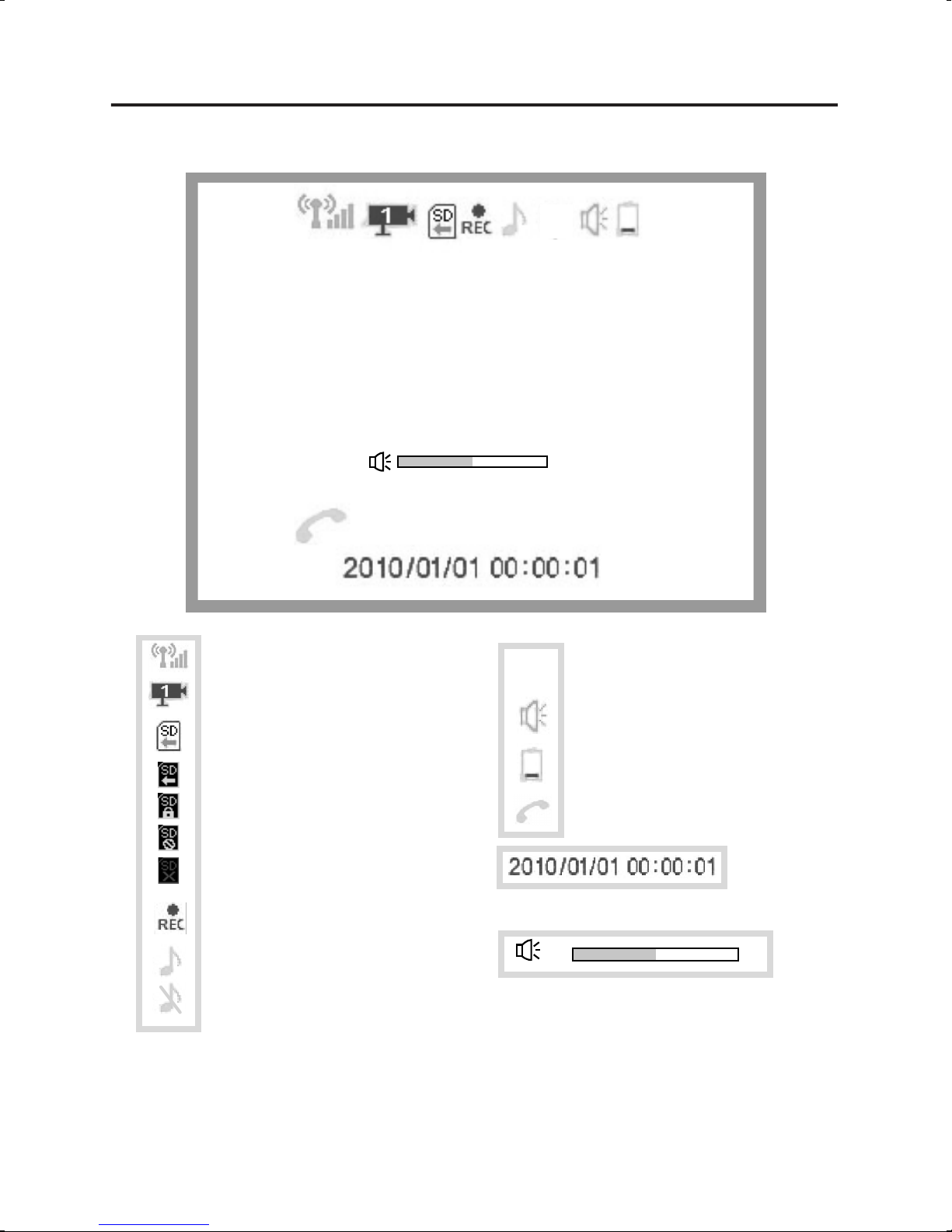
I. Get to Know the Display Icons ........................................................
II. Get to Know the Main Menu ...........................................................
System Setup - Time Setting / Factory Default ...............................
Camera Setup - Turn Camera(s) On/Off / Camera Scan Period.....
Pairing a Camera / Power Save Mode / SD Card Format ..............
VOX Setting - VOX Sensitivity / Enable VOX Recording.................
Brightness........................................................................................
Alarm Setup / Event List .................................................................
About Digital Wireless Technology ........................................................
Troubleshooting .......................................................................................
Product Specifications ............................................................................
Storage Media Management ...........................................................
Warranty ...................................................................................................
2
4
5
7
8
9
9
9
10
10
11
11
12
13
14
14
15
16
17
18
18
18
Contents

5
9. PTT (Push to Talk) / OK Confirm
10. Power button
11. SD card slot
12. USB port
13. DC IN jack
14. Reset
15. Power adaptor
1. Battery Indicator
2. Power Indicator
3. Cursor up / Channel switch
4. Cursor left / Volume down
5. Cursor down / Lullaby play button
6. Cursor right / Volume up
7. Enter / Exit Menu button
8. Record / Delete
BSU
LCD Monitor (Receiver)
8. Power / Lullaby play switch
9. Pairing Key
10. Reset
11. DC IN Jack
12. Power Adaptor
13. Goose Neck Mount Stand
1. Lens
2. IR (Infra Red) LEDs
3. EDS (sensor)
4. Battery Indicator
5. Link Indicator
6. Power Indicator
7. Microphone
DC IN 5V/1A
PWR.
13
Camera
Parts of the BW2101 Baby Monitoring System

6
Camera Connection
1. Connect the power cable to the
camera’s DC IN jack and then plug
the power adaptor to a 240VAC wall
outlet.
2. Slide the power switch down once to
turn ON the camera.
NOTE! The built-in Lithium battery
charges automatically when the power
adaptor is connected. Charge the
battery to full capacity before using the
monitor in portable mode. The battery
is at full capacity when the green
(battery indicator) turns off.
NOTE! Only use the 5V/1A power
adaptor provided in the package.
1
2
DC IN 5V/1A
Step 1. Connection & Installation
Getting Started
1
2
NOTE! The built-in Lithium battery
charges automatically when the power
adaptor is connected. Charge the
battery to full capacity before using the
monitor in portable mode.
NOTE! Only use the 5V/1A power
adaptor provided in the package.
LCD Monitor Connection
NOTE! In portable mode, charge the
battery when the battery indicator lights
up red.
1. Connect the power cable to the
monitor’s DC IN jack and then plug
the power adaptor to a 240VAC wall
outlet.
2. Press the power button to turn ON
the monitor.

7
2. Mount the camera onto the bracket,
but do not tighten.
3. Adjust the camera to the proper
view angle. Make sure the lens is
upright relative to your subject. Then
tighten the lock nut to secure the
camera.
Wall mount option
1. Select the position for the mount
stand and mark out the mount holes.
The two wall screws should be
spaced 40mm apart. Screws and
anchors are supplied, but if
necessary use an appropriate screw
type for the mounting surface.
Desktop mount option
1. Select the position for the camera
and secure the camera stand.
Installing the Camera on the Goose Neck Mount Stand
5. At the LCD monitor adjust the
antenna to an upright position.
4. Connect the AC adaptor and route
the cord along the guides in the
stand.
Getting Started (cont’d)
Use the goose neck mount stand to install the camera at an appropriate angle
in a semi-permanent (desktop mount option) or permanent (wall mount option)
location.
NOTE! Ensure the install location is within range of a 240VAC wall outlet.
locknut
cord guides

8
Step 2: Basic Operation
DC IN 5V/1A
PWR.
I. Get to Know the Camera
(4) Power / Lullaby Play Switch
Slide down once to power ON the camera. To power OFF, slide down
and hold the switch for 2 seconds until the power indicator turns off.
(5) Link Button
Press to pair the camera with the LCD monitor.
See Advanced Operation - Pairing Camera.
(1) Battery Indicator
Green LED: Battery Charging; charge battery until Green LED turns off.
Red LED: Battery Low (portable mode); Camera will turn off within 3
minutes. Connect the power adaptor for charging or
continuous use.
LED off: Battery fully charged.
(2) Link Indicator
Flashing LED: Pairing sequence is in process. See Advanced Operation
- Pairing Camera section as a guide.
LED OFF: Camera is in stand-by mode.
(3) Power Indicator
LED turns ON when camera is powered ON.
After power on; slide down to turn on the lullaby play of the camera, long
slide & hold to turn off.
Blue LED: Camera is picked up by the LCD monitor.

9
II. Get to Know the LCD Monitor
BSU
(10) Power Button
Press to turn power ON, press and hold for 2 seconds to turn
power OFF.
(1) Battery Indicator
Green LED: Battery charging; charge the battery until the Green
LED turns off.
Red LED: Battery Low (portable mode); Monitor will turn off within
3 minutes. Connect the power adaptor for charging or
continuous use.
LED off: Battery fully charged.
(2) Power Indicator
LED turns ON when monitor is powered ON.
NOTE! LED remains ON while LCD display is OFF in Power Save mode.
(3) View next camera (CH1-4) Cursor Up Hot key CH1
(5) Lullaby Play Switch Cursor Down Hot key CH2
(6) Volume up Cursor Right Hot key CH4
(8) Manual Record Delete Record File
(4) Volume down Cursor Left Hot key CH3
(7) Enter Menu Mode ESC (back)
(9) Push to Talk OK (confirm)
Step 2: Basic Operation (cont’d)
Standard View Mode Menu Mode Quad View Mode

10
NOTE! Volume bar is blue when Monitor
volume is adjusted.
NOTE!
Volume bar is green when Camera
lullaby volume is adjusted.
a.
b.
d.
k.
j.
c.
e.
f.
g.
h.
i.
Battery low indicator (Cam)
Push-to-talk indicator
VOX record ON
VOX alarm ON
Lullaby play indicator
Lullaby mute
Signal indicator
Current Channel indicator
Record indicator (flashing) System time
- locked (flashing)
- error (flashing)
- full (flashing)
- available
3
Volume Bar
SD Card
VOX
I. Get to Know the Display Icons
Step 3: Advanced Operation
a b c d e f g h
i
j
VOX
k
3

11
System Setup - Set to Factory Default
2. Press OK to save.
4. Use / to select a setting if
necessary.
1. Use / to select between
No and Yes.
Advanced Operation (cont’d)
System Setup - Time Setting
1. Use / / / to change
the setting.
Set the date and time used for Event
List recording.
2. Press OK to save.
II. Get to Know the Main Menu
5. Press ESC to go back or exit the
menu.
3. Press OK to enter the setting menu.
2. Use / / / to highlight a
menu option.
1. Press MENU in standard view mode
to display the main menu (the
example shows the menu with the
Brightness option highlighted).

12
1. Use / to change Scan Time
interval from OFF / 5 sec / 15 sec
/ Quad.
NOTE! To leave Quad display, simply
press directional keys to enter single
channel view.
NOTE! When system enters into
power save mode from Quad, press
any key to resume monitor view.
= CAM1; = CAM2;
= CAM3; = CAM4;
2. Press OK to confirm the settings.
Camera Setup - Camera Scan Period
1. Use / to select the camera
you want to turn off.
2. Press OK to change ON/OFF status.
NOTE! Make sure available cameras
are set to ON for SCAN or Quad mode.
Camera Setup - Turn Camera(s) On/Off
Advanced Operation (cont’d)
II. Get to Know the Main Menu (cont’d)

13
Press / to select No or Yes.
NOTE! For first time use, it is strongly
recommended to format the SD card.
SD Card Format - SD Card Format
Use / to turn Power Saving
mode On/Off.
NOTE! By setting Power Saving mode
ON, both receiver and camera will
enter standby mode after 2-minute
idle time and speaker volume will be
mute. Press power key of the receiver
to resume monitor and camera .
Power Saving - Power Saving
II. Get to Know the Main Menu (cont’d)
Advanced Operation (cont’d)
1. Use / to select a channel.
2. Press OK to start system
countdown from 60 seconds.
3. Within the 60 second countdown
press PAIR at the camera side. The
camera signal will display when
pairing is complete.
Pairing - Pairing a Camera

14
Brightness - Brightness
Press OK to enter camera brightness
adjustment bar, press / to adjust
brightness of current channel.
When set to ON, the system will auto
record for 30 sec when the camera is
triggered by voice.
NOTE! Please set VOX sensitivity to
level 1~3 to enable use of this function.
VOX Setting - VOX Sensitivity
NOTE! At OFF setting the VOX
function is disabled.
Level 1 - low sensitivity
Level 3 - high sensitivity.
Use / to adjust the VOX
sensitivity level.
VOX Setting - Enable VOX Recording
Advanced Operation (cont’d)
II. Get to Know the Main Menu (cont’d)

15
Playback Mode
1. Press OK to enter the Record folder.
2. Press OK again to Play/Pause a file.
3. Press to fast forward the video
clip.
Press to rewind the video clip.
Press ESC to Stop/Exit.
1. Use / to select the record file
you want to delete.
2. Press DEL to enter delete mode.
3. Press / to select YES or NO.
4. Press OK to delete.
Managing the Event List
NOTE! Recording files will be saved
every 30 seconds if recording time
exceeds 30 seconds.
Event List - Event List
2. Press OK to shift to on /off.
Battery low alarm ON: The monitor
will give an alarm for 15 seconds when
the camera battery is low.
Out of range alarm ON: The monitor
will give an alarm for 15 seconds when
the monitor and camera(s) are out of
wireless transmitting range.
VOX alarm ON: The monitor will give
an alarm for 15 seconds when the
camera is triggered by voice.
1. Use / to move between the
items.
Alarm Setup - Alarm Setup
Advanced Operation (cont’d)
II. Get to Know the Main Menu (cont’d)

16
If possible, remove obstacles in betwen the camera or the monitor that might
reflect the signal. These could include furniture, cabinets, and walls. If you feel
the wireless signal is not good enough, place the moniotr at a new angle or
re-adjust its position to make an improvement. Or simply relocate the camera
closer to the monitor.
In order to provide a private and interference free wireless service, this digital
wireless solution works on a 2Mb narrow hopping band. Different from
traditional 2.4GHz analog signal, this digital wireless signal is compressed and
presented as Motion JPEG (MJPEG) format. By digitizing and compressing the
raw analog data, the bandwidth is used more efficiently and securely.
Consequentially, you might observe an indent image line if the signal is viewed
on a larger display monitor or plasma TV.
How to improve the wireless signal quality
Why Image Compression?
This innovative digital wirelss solution integrates advance Frequency Hopping
Spread Spectrum (FHSS) technolgy. This technology greatly reduces the
interference that comes from other devices using the same radio frequency
(2.4GHz), e.g. WIFI, Bluetooth, cordless phone...etc. You now can experience
improved wireless surveillance quality without flicker and noisy images.
However, weaker signals (lag or still image) may be observed from time to
time, depending on the environment where the system is installed.
Complies with FCC part 15.247, ETSI (EN) 300 328; audio / video signals
transmitted out up to about 500 foot (150 metres) line of sight can be
supported. Line of sight installation though, is usually not a common practice.
Factors affecting transmission include microwave ovens or other high
frequency electromagnetic waves. Reinforced concrete walls, large scale metal
products and metal furniture should not be located near the camera or the
monitor unit. Do not place near water. Human bodies such as a person passing
through may cause unstable signal quality.
About 2.4GHz Digital Wireless Signal
This section offers some helpful information to overcome most problems you
may encounter.
Problem Diagnosis
About Digital Wireless Technology

17
Power save
mode on
Camera and
receiver are
too close
The camera has a high sensitivity
microphone. Keep the camera at least 10
feet away from the receiver. If the camera
must be within 10 feet of the receiver,
keep the volume down.
Press power key to resume receiver
image, please refer to Power Saving
section on page 13 for details.
Black screen
& Buttons not
functioning
Audio
feedback
VOX Record
& Alarm does
not work
VOX Menu
set to “OFF”
Set VOX Sensitivity / VOX Alarm
/ VOX Record to ON.
No power supply
to camera
(Battery low)
Camera is not
paired with
receiver
Check power adaptor and power cable
connection or battery been run out.
See pairing operation for detail.
Recording
does not
work
Low signal
or unstable
signal
System
Message
shows
“NO Signal” Service out of
range
Move the camera closer to the monitor.
If possible, remove major obstacles in
between the camera and monitor. Or
relocate the camera to a different location.
Signal being
blocked
Antenna direct
-ional limitation
Signal being
blocked
Adjust camera and monitor position.
If possible, remove major obstacles in
between the camera and monitor. Or
relocate the camera to a different location.
Keep WiFi router away from the camera
and/or monitor.
Keep working motors (hair dryer / heat fan
/ air conditioner / water pump) or
microwave oven away from the camera
and/or monitor.
Insert SD card to SD card slot.
Unlock the SD card.
Strong radio
signal near by
Strong electro
-magnetic inter
-ference near by
No SD card
SD card locked
RemediesPossible CausesProblem
If you have any trouble with your phone, check this section first. If you need
help, visit the customer support page of our website listed on the front cover.
Troubleshooting Guide

18
UNIDEN BW2101
Important:
Satisfactory evidence of the original purchase is required for warranty service
Please refer to our Uniden website for any details
or warranty durations offered in addition to
those contained below.
Warrantor:
The warrantor is either Uniden Australia Pty Limited ABN 58 001 865 498 (“Uniden Aust”) or
Uniden New Zealand Limited (“Uniden NZ”) as the case may be.
Terms of Warranty:
Uniden Aust/NZ warrants to the original retail purchaser only that the
BW2101 (“the Product”), will be free from defects in materials and craftsmanship for the
duration of the warranty period, subject to the limitations and exclusions set out below.
Warranty
130 minutes
270 minutes
1050 minutes
2100 minutes
Recording Time
SD Card Capacity
1 GB
2 GB
8 GB
16 GB
Storage Media Management
680 mA (max)
DC 5V / 1A
Maximum Channels
Communication Range
Resolution
Operating Temperature
Operating Voltage
Current Consumption
Night Vision
Dimension
Camera Unit Monitor Unit
1
300 metres in open space
-10°C ~ +40°C
640 x 480 (VGA)
DC 5V / 1A
3m
680 mA (max)
60mm (W)
116mm (H)
32mm (D)
130mm (W)
90mm (H)
27mm (D)
Product Specification

19
UNIDEN AUSTRALIA PTY LTD
Service Division
345 Princes Highway,
Rockdale, NSW 2216
Phone number: 1300 366 895
Email: [email protected]
UNIDEN NEW ZEALAND LTD
Service Division
150 Harris Road, East Tamaki
Auckland 2013
Phone number: (09) 273 8377
Email: [email protected]
Warranty period: This warranty to the original retail purchaser is only valid in the original
country of purchase for a Product first purchased either in Australia or New Zealand and will
expire one (1) year from the date of the original retail sale. If a warranty claim is made, this
warranty will not apply if the Product is found by Uniden to be:
Damaged or not maintained in a reasonable manner or as recommended in the relevant
Uniden Owner’s Manual;
Modified, altered or used as part of any conversion, kits, subassemblies or any configura-
tions not sold by Uniden Aust or Uniden NZ;
Improperly installed contrary to instructions contained in the relevant Owner’s Manual
Repaired by someone other than an authorized Uniden Repair Agent in relation to a defect
or malfunction covered by this warranty; or
Used in conjunction with any equipment, parts or a system not manufactured by Uniden.
Parts Covered: This warranty covers the Product and included accessories.
User-generated Data: This warranty does not
cover any claimed loss of or damage to
user-generated data (including but without limitation phone numbers, addresses and images)
that may be stored on your Product.
Statement of Remedy: If the Product is found not
to conform to this warranty as stated above,
the Warrantor, at its discretion, will either repair the
defect or replace the Product without any
charge for parts or service.
This warranty does not include any reimbursement
or payment of any consequential damages
claimed to arise from a Product’s failure to comply with the warranty.
Our goods come with guarantees that cannot be
excluded under the Australian Consumer Law.
You are entitled to a replacement or refund for a major failure and for compensation for any
other reasonably foreseeable loss or damage. You are also entitled to have the goods repaired
or replaced if the goods fail to be of acceptable quality and the failure does not amount to a
major failure.
This warranty is in addition to and sits alongside
your rights under either the COMPETITION
AND CONSUMER ACT 2010 (Australia) or the CONSUMER GUARANTEES ACT (New
Zealand) as the case may be, none of which can be excluded.
Procedure for obtaining warranty service:
Depending on the country in which the Product
was first purchased, if you believe that your Product does not conform with this warranty, you
should deliver the Product, together with satisfactory evidence of your original purchase (such
as a legible copy of the sales docket) to Uniden at the addresses shown below. You should
contact Uniden regarding any compensation that may be payable for your expenses incurred
in making a warranty claim. Prior to delivery, we recommend that you make a backup copy of
any phone numbers, images or other data stored on your Product, in case it is lost or damaged
during warranty service.
A)
B)
C)
D)
E)

© 2011 Uniden Australia Pty. Limited.
Uniden New Zealand Limited. Printed in PRC.
Table of contents
Other Uniden Baby Monitor manuals

Uniden
Uniden Lullaboo G403 User manual

Uniden
Uniden Guardian UBR243 User manual

Uniden
Uniden BW614PTR User manual

Uniden
Uniden BW5151R Series User manual

Uniden
Uniden BW31 Series User manual

Uniden
Uniden BW615PTR User manual

Uniden
Uniden BW2001 User manual

Uniden
Uniden BW4151 User manual

Uniden
Uniden BW6181R Series User manual

Uniden
Uniden BW150R User manual

Uniden
Uniden BW30xx Series User manual

Uniden
Uniden BW6151R Series User manual

Uniden
Uniden BW3451R+1 User manual

Uniden
Uniden BW120 User manual

Uniden
Uniden BW130 User manual

Uniden
Uniden BW140R User manual

Uniden
Uniden BW4351 User manual

Uniden
Uniden BW618PTR User manual

Uniden
Uniden BW4301 User manual

Uniden
Uniden UBW2101 User manual