Uniflame UFPDS1101BLK User manual

1PB
ATTACH YOUR RECEIPT HERE
Questions, problems, missing parts? Before returning to your retailer, call our customer
service department at: 1-888-398-8643, 8 a.m. - 8 p.m., EST, Monday - Sunday. You can
GLASS
FIREPLACE
DOORS
UniFlame and logo design are trademarks or registered
trademarks of Mr.Bar-B-Q, LLC. All rights reserved.
Français p. 13
Español p. 25
SM21426
Model No. Model No. Model No. Model No. Model No.
UFPDS1101BLK
UFPDS1102GUN
UFPDS1103ORB
UFPDM1204BLK
UFPDM1205GUN
UFPDM1206ORB
UFPDL1307BLK
UFPDL1308GUN
UFPDL1309ORB
UFPDS1501BLK
UFPDS1502GUN
UFPDS1503ORB
UFPDM1604BLK
UFPDM1605GUN
UFPDM1606ORB
UFPDM1104BLK
UFPDM1105GUN
UFPDM1106ORB
UFPDL1207BLK
UFPDL1208GUN
UFPDL1209ORB
UFPDS1401BLK
UFPDS1402GUN
UFPDS1403ORB
UFPDM1504BLK
UFPDM1505GUN
UFPDM1506ORB
UFPDL1607BLK
UFPDL1608GUN
UFPDL1609ORB
UFPDL1107BLK
UFPDL1108GUN
UFPDL1109ORB
UFPDS1301BLK
UFPDS1302GUN
UFPDS1303ORB
UFPDM1404BLK
UFPDM1405GUN
UFPDM1406ORB
UFPDL1507BLK
UFPDL1508SLV
UFPDL1509ORB
UFPDS1201BLK
UFPDS1202GUN
UFPDS1203ORB
UFPDM1304BLK
UFPDM1305GUN
UFPDM1306ORB
UFPDL1407BLK
UFPDL1408GUN
UFPDL1409ORB
UFPDS1601BLK
UFPDS1602GUN
UFPDS1603ORB
KEEP THIS MANUAL FOR FUTURE REFERENCE
Model No._____________________________ Size ________________________
Finish _________________________ Dimensions ________________________
This information can be found on the carton label.
WARNING
DO NOT close the glass doors until
the fireplace has completely cooled.
(English Version)

32
TABLE OF CONTENTS
Installation Guidelines .......................................................................................................................................... 2
Package Contents / Hardware.............................................................................................................................. 3
Safety Information ................................................................................................................................................ 4
Preparation & Installation Video QR Code ........................................................................................................... 4
Installation Instructions......................................................................................................................................... 5
Care and Maintenance ....................................................................................................................................... 10
Warranty ..............................................................................................................................................................11
INSTALLATION GUIDELINES
• Thisglassdoorunitisdesignedtooverlapandcoverthefrontofyourreplaceopeningandonlycovers
acertainrangeofreplacesizes.
Toensureyouhavepurchasedthecorrectdoorunitforyourreplace,seethechartbelow:
• Thisglassdoorunitisonlyintendedforbrickandmortar(masonry)replaces.Donotinstallthisunitona
prefabricated(metal)replace.
• Be sure to check with your local municipality for any regional ordinances or codes before installing this unit.
SIZE OVERALL DOOR DIMENSIONS FITS FIREPLACE OPENING
Width x Height Width Height
Small 37.5” x 30”* 30” - 37” 22.5” - 29.5”
Medium 37.5” x 33”* 30” - 37” 25.5” - 32.5”
Large 43.5” x 33”* 36” - 43” 25.5” - 32.5”
*Height includes a 2” riser bar (not assembled). See assembly instructions for details.

32
PACKAGE CONTENTS / HARDWARE
ABCD
E F
G
H J
K
L
PART DESCRIPTION QTY
ALong T-Bracket 2
BShort T-Bracket 2
C Lintel Clamp 2
DPressure Bracket 2
E Long Thumbscrew (1/4-20 x 3 1/2”) 2
F Short Thumbscrew (1/4-20 x 2”) 2
G Long Machine Screw (8-32 x 5/8”) 4
H Hex Nut 4
I Thread Cutting Screw (#10 x 1”) 4
J Short Machine Screw (1/4-20 x 1/4”) 4
M
N
O
R
Q
I
PART DESCRIPTION QTY
KHeat-Resistant Fiberglass
Insulation (Narrow Pieces: 2” Wide) 3
LHeat-Resistant Fiberglass
Insulation (Wide Pieces: 3” Wide) 3
M Riser Bar 1
NDoorHandlewith2Screws(M4x20) 2
ODoorFrame 1
PLeftDoor 1
QRightDoor 1
R Left Screen 1
S Right Screen 1
S
P

54
Beforeinstallingyourreplacedoors,besuretoreadallsafetyandassemblyinformationtoensuretheproper
operation of the unit. If you have any questions regarding the proper use of this product, be sure to contact our
customer service department, whose contact information is found in our warranty.
WARNINGS
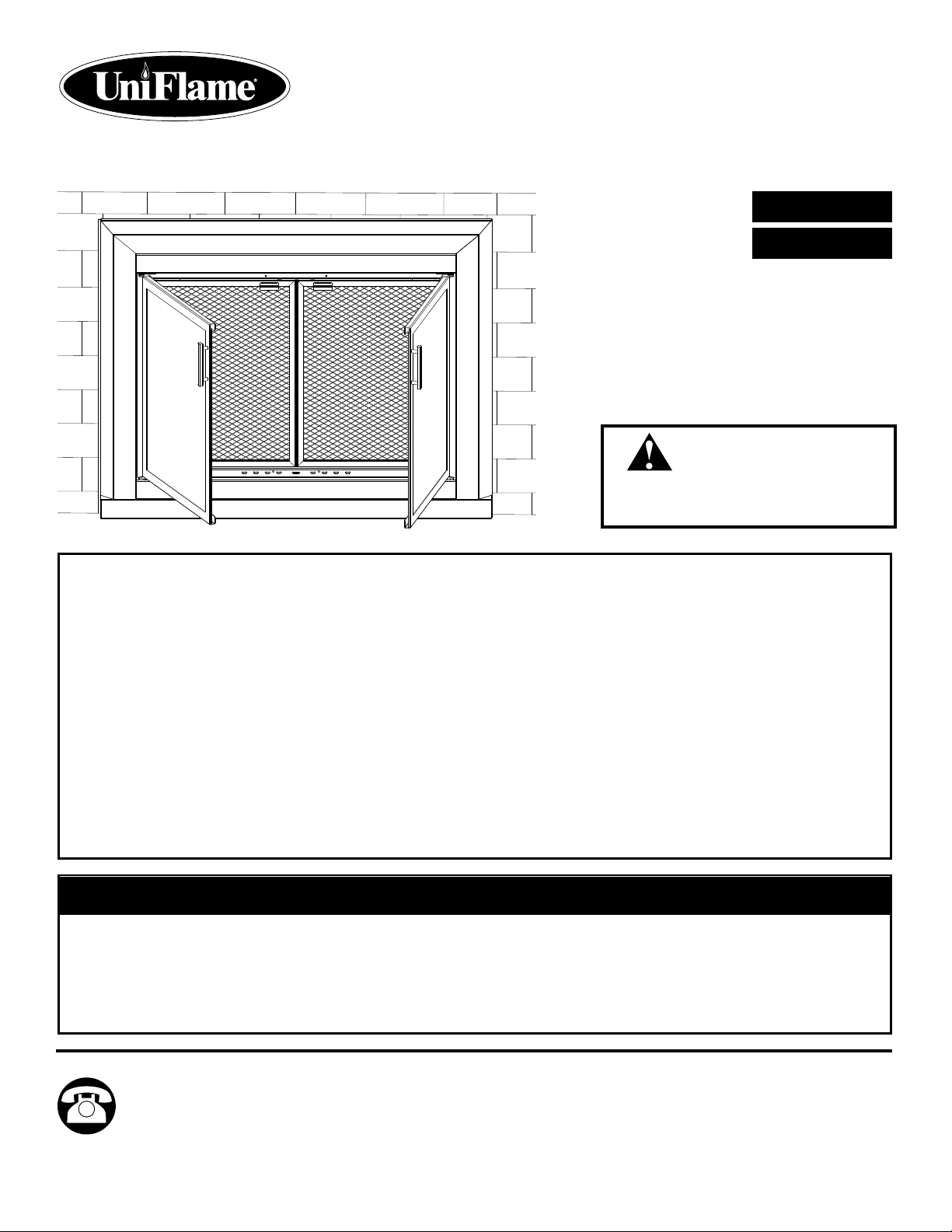
• DO NOT closetheglassdoorsuntilthereplacehascompletelycooled.
• DO NOT closetheglassdoorswhileareisburninginthereplace.Eventhoughthedoorsare
made of tempered glass, the glass can still shatter if exposed to excessive heat.
•
DO NOTleavethescreendoorsopenwhilethereisburning.Besuretoleavethescreendoors
closedwhileareisburninginthereplace.Thiswillpreventsparksfromescapingfromthereplace.
•DO NOT allow any cold liquid or substance to come in contact with the glass doors while they are
hot. This could cause the glass to shatter.
•
DO NOT buildarethatistoolargeorplacetherewoodgratetooclosetothescreendoorsto
avoid discoloration of the frame.
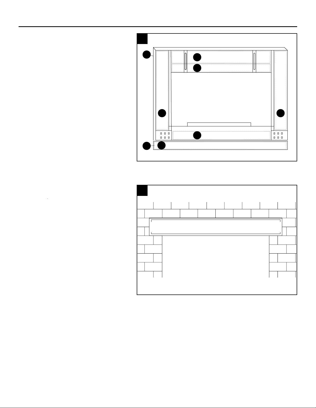
• DO adjustthedamperfoundatthebottomfrontofthescreendoorstoallowforproperairowinto
yourre.
WARNING: This product can expose you to chemicals, including lead and lead components which
are known to the State of California to cause cancer, birth defects, and other reproductive harm.
Wash your hands after handling this product. For more information go to www.P65Warnings.ca.gov.
FIREPLACE PRECAUTIONS
•Beforeoperatinganewreplace,besuretoneutralizethereplacebyapplyingadilutedsolution
of ammonia, followed by a warm then cold rinse.
•Neverstorecombustibleorvolatilesubstancesinsidethereplace.
•Keepallcombustibleandvolatilesubstancesawayfromthefrontofthereplace.
•Donotuseanycombustibleorvolatilesubstancestohelpstartare.
•Openthechimneydamperbeforestartingare.
•Keepchildrenandpetsawayfromthereplacewhileinuse.
•Donottouchanypartoftheglassdoorunitwithyourbarehandswhileareisburning.
Always use an insulated glove to open and close the doors and damper.
•Neveruseyourreplaceasanincinerator.
• Always allow ashes to fully burn out and cool before disposing.
SAFETY INFORMATION
PREPARATION
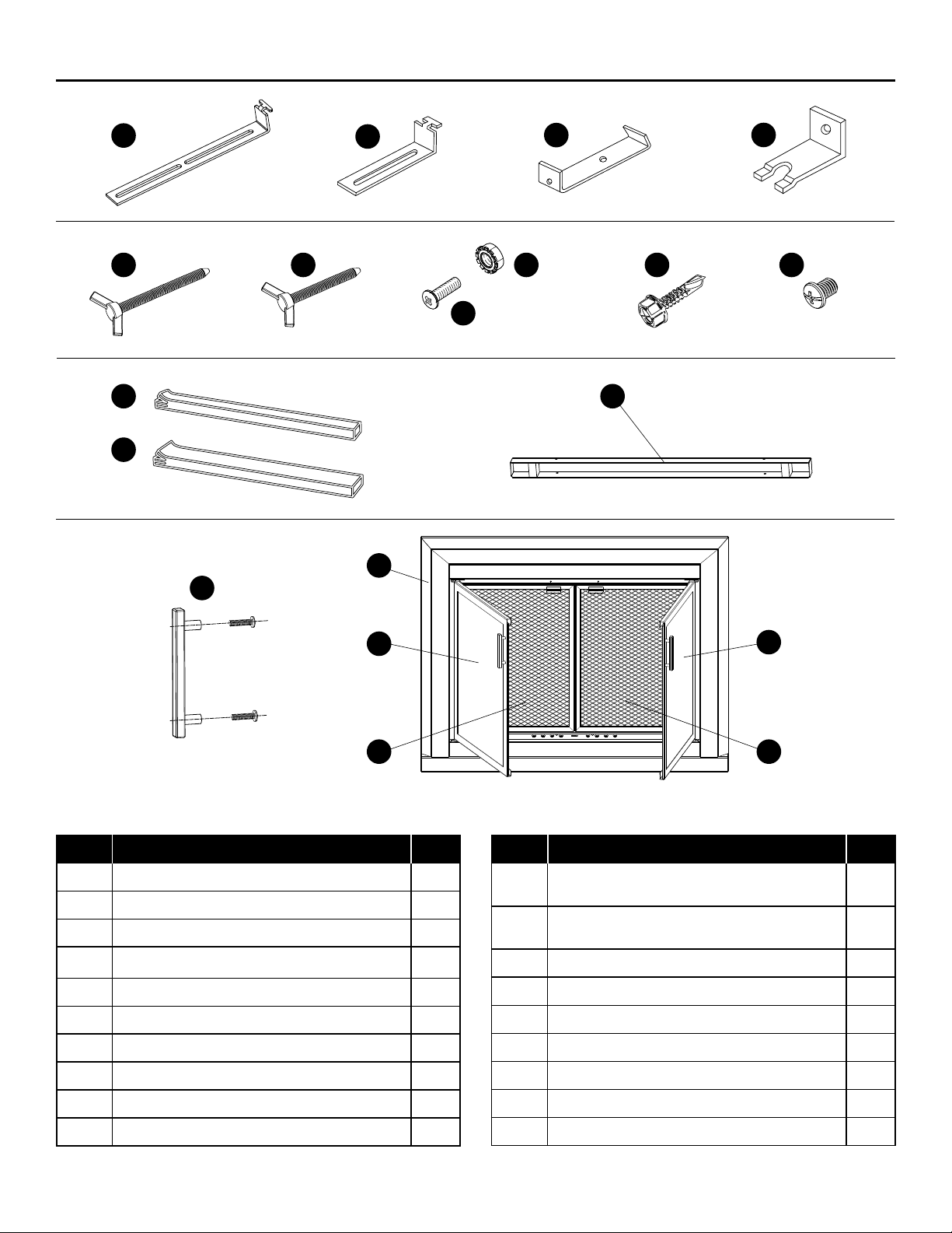
Before beginning assembly of product, make sure all parts are present.
Compare parts with package contents list. If any part is missing or
damaged, do not attempt to assemble the product.
Package Removal: Carefully remove the glass door unit and all other
pieces from the box, placing the glass door unit face down on a soft
atsurface.
Tools Required for Assembly (not included): Flathead Screwdriver,
Phillips Head Screwdriver, Work Gloves, Measuring Tape, Scissors
INSTALLATION VIDEO
Scan QR code below
for assembly video.

54
INSTALLATION INSTRUCTIONS
DETERMINING IF THE RISER BAR
IS NEEDED
• You may or may not need to install the
riser bar, depending on the height of
yourreplace.
• To determine if you need the riser bar,
place the glass door unit in front of
yourreplacetoseeifittsyour
replaceopening.
• If the top of the glass door unit does not
reachthetopofyourreplaceopening,
you can install the Riser Bar to the bottom
of the unit to add extra height to the unit.
1
Riser Bar
M
O
1. RISER BAR INSTALLATION
To attach the riser bar:
•Laytheunitfacedownonasoftatsurface.
• Attach the Riser Bar (M) to the bottom
of the unit by inserting the Long Machine
Screws (G) through the holes in the Riser
Bar and the holes on the bottom of the
unit, as shown.
• Secure the Long Machine Screws using
the Hex Nuts (H), as shown.
Hardware Used
Long Machine Screws (x2)
Hex Nuts (x2)
G
H
H
G
M

76
View from Inside of Fireplace
Lintel Bar
3. LOCATING THE LINTEL BAR
• The lintel bar is the L-shaped metal bar
that runs along the top of the inside
openingofyourreplace,holdingthe
bricks in place.
3
INSTALLATION INSTRUCTIONS
2. INSERTING THE INSULATION
• Be sure to wear work gloves while
handling the insulation strips.
•Triminsulationstripstotwithscissors.
• Lay the unit face down on a soft
atsurface.
• Insert the Wide (L) and Narrow (K) Strips
of Fiberglass Insulation into the wide
and narrow gaps on the back of the unit,
including the Riser Bar.
2
Wide Insulation
Narrow Insulation
Wide Insulation
Wide Insulation
Narrow Insulation
Narrow Insulation (only if Riser Bar is required)
L L
L
K
K
K
O
M
76

76
INSTALLATION INSTRUCTIONS
76
INSTALLATION INSTRUCTIONS
5. ASSEMBLING THE BRACKETS
Before attaching the unit to your lintel bar, you have to assemble the brackets.
•YouwilluseeithertheLongT-Brackets(A)ortheShortT-Brackets(B)toattachtheunittoyourreplace,
depending on the width of your lintel bar.
• Use a measuring tape to measure the width of your lintel bar, measuring from the back of the lintel bar
tothefrontofyourreplace.
• Use the width measurement of your lintel bar to determine whether you will need the Long T-Brackets
or the Short T-Brackets.
• Assemble the 2 T-Brackets (long or short) to the 2 Lintel Clamps (C), using the Short Machine Screws (J).
•Donotover-tightenthemachinescrewsyet.Leavethemloose.Youwilltightenthemlaterwhenyouadjust
the width of the clamp.
• Insert the Short Thumb Screws (F) into the back of the Lintel Clamps, as shown.
NOTE: You can assemble the T-Brackets to the Lintel Clamps either face-up or face-down (as shown),
dependingontheheightofyourreplace.Tryitface-uprst.Iftheclampsdonottyourreplaceproperly,
you can always go back and re-assemble them face-down.
Hardware Used
Long T-Brackets (x2) or Short T-Brackets (x2)
Lintel Clamps (x2)
Short Machine Screws (x2)
Short Thumb Screws (x2)
AB
C
J
5
F
Long T-Bracket,
Face-up
Long T-Bracket,
Face-down
Short T-Bracket,
Face-up
Short T-Bracket,
Face-down
F
C
J
AB

98
INSTALLATION INSTRUCTIONS
6. INSERTING THE ASSEMBLED BRACKETS INTO YOUR DOOR UNIT
Now that the brackets are assembled, you are ready to attach the door unit to your lintel bar. (Recommendation:
This part of the installation might require 2 people – one person to hold the unit in place, while the other person
clampstheunittothereplace.)
• Insert the “T” of each T-Bracket into the slots found on the back of the door unit. Insert each “T” vertically into the
slot,andthenturnituntilit’shorizontal.TheassembledT-Brackets/LintelClampsshouldnowbehangingloosely
in the slots.
6
O
AB
or
7A. ATTACHING THE UNIT TO YOUR LINTEL BAR
• Open both the glass doors and the screen doors
on the unit.
• With the doors open, place the unit against the front
ofyourreplaceopening.(Thisiswhereyoumay
need assistance holding the unit in place while you
clamp it to the lintel bar.)
•Withtheunitinplace,reachinsidethereplace
and position the T-Bracket/Lintel Clamp over the
lintel bar.
• Adjust the width of the T-Bracket/Lintel Clamp until
it is snugly grasping the lintel bar and tighten the
Small Machine Screw.
•WiththeT-Bracket/LintelClampttingsnuglyover
the lintel bar, tighten the thumb screw until the unit
isheldrmlyinplace.
• With both thumb screws securely tightened, the unit
isnowrmlyattachedtothetopofyourreplace.
7A
Lintel Bar
Clamp
O

98
INSTALLATION INSTRUCTIONS
7B. ALTERNATE ATTACHMENT METHOD FOR THE TOP OF THE DOORS ONLY
IftheattachmentBracketsandLintelClampsdonotattachtoyourreplace,usethisalternateattachmentmethod.
Additional Tools Required: Electric Drill, 7/32” High Speed Steel Bit, Pencil and Safety Glasses
(RECOMMENDATION: This part of the installation might require 2 people – one person to hold the unit in place,
whiletheotherpersonmeasuresandattachestheunittothereplace.)
•SelectaT-Bracketthatwillsitushwithyourlintel
bar: Long T-Brackets (A) or Short T-Brackets (B).
• Attach the selected T-Bracket to the door. Place the
glassdoorsagainstthereplaceopeningandcenter.
• Use your pencil and mark through the T- Bracket,
on the lintel. Mark both sides.
• Remove the glass doors and drill a 7/32” hole into
the lintel bar at each marked location.
•Placetheglassdoorsagainstthereplaceopening
and line up the brackets to the holes in the lintel bar.
• Use the Thread Cutting Screw (I) to attach both
T-Brackets to the lintel bar.
Hardware Used
Long T-Brackets (x2)
Short T-Brackets (x2)
Thread Cutting Screws (x2)
I
8. SECURING THE BOTTOM
OF THE UNIT TO THE WALL
• Insert the 2 Long Thumbscrews (E) into the
2PressureBrackets(D),asshown.
• Insert the Pressure Brackets into the holes found on
the bottom of the back of the door unit. Choose the
holesthatwillbesttthesizeofyourreplace.
• Tighten the Long Thumbscrews until the point of each
thumbscrew is digging into the brick on the side of
yourreplace.
• If the thumbscrews do not reach the brick or are too
long, you can re-position the Pressure Brackets by
insertingthemintoadierentsetofholesontheunit.
Your glass door unit is now securely attached
toyourreplace!
Hardware Used
Pressure Brackets (x2)
Long Thumbscrews (x2)
D
E
8
D
E
7B
A
B
A
B
or
I
Lintel Bar
O

1110
INSTALLATION INSTRUCTIONS
9. GLASS DOOR ADJUSTMENT
Note: some models do not have these hinge
styles and therefore this step can be skipped.
The glass doors are attached to your unit with
4 hinges (2 hinges on each door). Each hinge
is attached to the frame of the unit with
2 adjustable screws.
If the glass doors are not aligned properly, they
can be easily adjusted:
• Loosen the 2 screws on one of the hinges.
DO NOT remove the screws – just loosen them.
• Adjust the position of the door.
• Once the door is positioned properly, re-tighten
the screws.
• If necessary, loosen the other hinge, adjust the
door, and re-tighten.
9
CARE AND MAINTENANCE
WARNING: DO NOT allow any cold liquid or substance to come in contact with the glass doors
while they are hot. This could cause the glass to shatter.
GLASS:
• Allow glass to cool fully before cleaning.
• Clean the glass with a diluted solution of ammonia and a clean cloth.
• DO NOT use scouring pads or harsh chemicals as it may damage the tempered glass.
FRAME:
• Clean the surface of the unit with a damp cloth.
•Ifnecessary,useadilutedsolutionofalcoholtoremovengerprintsorothermarkings.
• DO NOT clean with scouring pads, harsh chemicals, cleaners, or solvents.
WARNING
DO NOT close the glass doors
until the fireplace has completely cooled.

1110
WARRANTY
We warrant to the original retail purchaser of this
product, and to no other person, that if this product is
assembled, maintained, and operated in accordance
with the printed instructions accompanying it, then for
a period of one (1) year from the date of purchase,
all parts in such product shall be free from defects in
material and workmanship. We may require reasonable
proof of your date of purchase. Therefore, you should
retain your sales slip or invoice. This Limited Warranty
shall be limited to replacement parts, which prove
defective under normal use and service and which
we shall determine in its reasonable discretion upon
examination to be defective. Before returning any parts,
you should contact our customer service department
using the contact information listed on the cover of
thismanual.Ifweconrm,afterexamination,adefect
covered by this Limited Warranty in any returned part,
and if we approve the claim, we will replace such
defective part without charge. If you return defective
parts, transportation charges must be prepaid by you.
We will return replacement parts to the original retail
purchaser, freight or postage prepaid.
This Limited Warranty does not cover any failures or
operatingdicultiesduetoaccident,abuse,misuse,
alteration, misapplication, improper installation or
improper maintenance or service by you or any
third party, or failure to perform normal and routine
maintenance on the product as set out in this owner’s
manual. In addition, the Limited Warranty does
not cover damage to the nish, such as scratches,
dents, discoloration, rust or other weather damage,
after purchase.
This Limited Warranty is in lieu of all other expressed
warranties. We disclaim all warranties for products
thatarepurchasedfromsellersotherthanauthorized
retailers or distributors, including the warranty of
merchantabilityorthewarrantyoftnessforaparticular
purpose.WEALSODISCLAIMANYANDALLIMPLIED
WARRANTIES, INCLUDING WITHOUT LIMITATION
THEIMPLIEDWARRANTIESOFMERCHANTABILITY
ANDFITNESSFORAPARTICULARPURPOSE.WE
SHALL HAVE NO LIABILITY TO PURCHASER OR
ANYTHIRD PARTYFORANYSPECIAL,INDIRECT,
PUNITIVE, INCIDENTAL, OR CONSEQUENTIAL
DAMAGES.Wefurtherdisclaimanyimpliedorexpress
warranty of, and assumes no responsibility for, defects
in workmanship caused by third parties.
ThisLimitedWarrantygivesthepurchaserspeciclegal
rights; a purchaser may have other rights depending
upon where he or she lives. Some jurisdictions do not
allow the exclusion or limitation of special, incidental or
consequential damages, or limitations on how long a
warranty lasts, so the above exclusion and limitations
may not apply to everyone.
Wedonotauthorizeanypersonorcompanytoassume
for it any other obligation or liability in connection with the
sale, installation, use, removal, return, or replacement of
its equipment, and no such representations are binding
on us. This warranty gives you specic legal rights,
and you may also have the other rights that vary from
state to state. As some states do not allow exclusions or
limitations on an implied warranty, the above exclusions
and limitations may not apply.
Printed in China

1312

1312
JOINDRE LE REÇU ICI
Des questions, des problèmes ou des pièces manquantes? Avantderetournerchezvotre
détaillant,communiquezavecnotreServiceàlaclientèleau18664399800,de8hà20h
(HNE),dulundiaudimanche.Vouspouvezaussilefaireparcourrielà
Uniameetlelogostylisésontdesmarquesdecommerceoudes
marques déposées de Mr. Bar-B-Q, LLC. Tous droits réservés.
SM21426
No de modèle No de modèle No de modèle No de modèle No de modèle
UFPDS1101BLK
UFPDS1102GUN
UFPDS1103ORB
UFPDM1204BLK
UFPDM1205GUN
UFPDM1206ORB
UFPDL1307BLK
UFPDL1308GUN
UFPDL1309ORB
UFPDS1501BLK
UFPDS1502GUN
UFPDS1503ORB
UFPDM1604BLK
UFPDM1605GUN
UFPDM1606ORB
UFPDM1104BLK
UFPDM1105GUN
UFPDM1106ORB
UFPDL1207BLK
UFPDL1208GUN
UFPDL1209ORB
UFPDS1401BLK
UFPDS1402GUN
UFPDS1403ORB
UFPDM1504BLK
UFPDM1505GUN
UFPDM1506ORB
UFPDL1607BLK
UFPDL1608GUN
UFPDL1609ORB
UFPDL1107BLK
UFPDL1108GUN
UFPDL1109ORB
UFPDS1301BLK
UFPDS1302GUN
UFPDS1303ORB
UFPDM1404BLK
UFPDM1405GUN
UFPDM1406ORB
UFPDL1507BLK
UFPDL1508SLV
UFPDL1509ORB
UFPDS1201BLK
UFPDS1202GUN
UFPDS1203ORB
UFPDM1304BLK
UFPDM1305GUN
UFPDM1306ORB
UFPDL1407BLK
UFPDL1408GUN
UFPDL1409ORB
UFPDS1601BLK
UFPDS1602GUN
UFPDS1603ORB
CONSERVER CE GUIDE AUX FINS DE CONSULTATION FUTURE
No de modèle________________________ Format ________________________
Fini ____________________________ Dimensions ________________________
Ces renseignements gurent sur l’étiquette de la boîte.
AVERTISSEMENT
NE fermez pas la porte en verre
tant que la cheminée n’est pas
complètement refroidie.
PORTES DE
FOYER EN
VERRE
English p. 1
Español p. 25
(French Version)

1514
TABLE DES MATIÈRES
Directivesd’installation......................................................................................................................................... 2
Contenu de l’emballage/quincaillerie.................................................................................................................... 3
Consignes de sécurité.......................................................................................................................................... 4
Code QR de la vidéo de préparation et d’installation ........................................................................................... 4
Mode d’installation................................................................................................................................................ 5
Entretien ............................................................................................................................................................. 10
Garantie...............................................................................................................................................................11
DIRECTIVES D’INSTALLATION
• Cette porte en verre est conçue pour chevaucher et couvrir l’ouverture du foyer et ne couvre qu’une certaine plage
de formats de foyers.
Pourvousassurerd’avoirachetélaporteconvenantexactementàvotrefoyer,consulterletableauci-dessous:
• Cette porte en verre est réservée aux foyers avec manteau en maçonnerie (brique et mortier). Ne pas installer
cette porte sur un foyer préfabriqué (en métal).
• Avantd’installercetteporte,assurez-vousdeconsulterlescodesetlaréglementationenvigueurdansvotre
municipalité.
FORMAT DIMENSIONS HORS TOUT DE
LA PORTE POUR OUVERTURES DE FOYER
Largeur x hauteur Largeur Hauteur
Petit 37.5” x 30”* 30” - 37” 22.5” - 29.5”
Moyen 37.5” x 33”* 30” - 37” 25.5” - 32.5”
Grand 43.5” x 33”* 36” - 43” 25.5” - 32.5”
*La hauteur comprend une garniture de cadre inférieure de 2 po (non montée). Consulter le
mode d’assemblage pour voir les détails.

1514
CONTENU DE L’EMBALLAGE/QUINCAILLERIE
ABCD
E F
G
H J
K
L
PIÈCE DESCRIPTION QTÉ
A Support long avec patte en T 2
B Support court avec patte en T 2
C Bride de linteau 2
D Supportàpression 2
EVisàoreilleslongue(1/4-20x31/2po) 2
FVisàoreillescourte(1/4-20x2po) 2
G Vis mécanique longue (8-32 x 5/8 po) 4
H Écrou hexagonal 4
I Vis autotaraudeuse (no 10 x 1 po) 4
J Vis mécanique courte (1/4-20 x 1/4 po) 4
M
N
O
R
Q
I
PIÈCE DESCRIPTION QTÉ
KFibre de verre thermorésistant Isolant
(Bandes étroites : 2 po largeur) 3
LFibre de verre thermorésistant
Isolant (Bandes larges : 3 po largeur) 3
M Garniture de cadre inférieure 1
N Poignée de porte et 2 vis (M4 x 20) 2
O Cadre de porte 1
P Porte gauche 1
Q Porte droite 1
R Pare-étincelles gauche 1
S Pare-étincelles droit 1
S
P

1716
Avantd’installerlesportesdufoyer,lireattentivementtoutel’informationrelativeàlasécuritéetaumontage
and’assurerlebonfonctionnementdelaporte.
MISES EN GARDE
• DEfermezpaslaporteenverretantquelacheminéen’estpascomplètementrefroidie.
•
NE PAS fermer les portes en verre lorsqu’un feu brûle dans le foyer. Bien que les portes
sont faites de verre trempé, celui-ci peut tout de même éclater s’il est exposé à une chaleur
excessive.
• NE PAS laisser les pare-étincelles ouverts lorsqu’un feu brûle dans le foyer. S’assurer
de fermer les deux pare-étincelles lorsqu’un feu brûle, an d’empêcher toute projection
d’étincelles hors du foyer.
•NE PAS laisser de substance froide ou de liquide froid entrer en contact avec les portes en
verre lorsque celles-ci sont chaudes, car le verre pourrait éclater.
•
NE PAS insérer une trop grande quantité de bûches dans le foyer ni placer le support à
bûches trop près des pare-étincelles an de prévenir la décoloration du cadre.
• RÉGLER le registre situé au bas des pare-étincelles de manière à ce qu’il y ait une circulation
d’air appropriée dans le foyer.
AVERTISSEMENT: Ceproduitpeutvousexposeràdessubstanceschimiques,notammentdu
plomb et des composants du plomb, lesquels sont reconnus par l’État de Californie comme causant
le cancer, des anomalies congénitales et d’autres troubles de la reproduction. Se laver les mains
aprèsavoirmanipuléceproduit.Pourensavoirdavantage,visitezlesitewww.P65Warnings.ca.gov.
MESURES DE PRÉCAUTION
• Avant d’utiliser un foyer neuf, s’assurer de neutraliser ses parois en y appliquant une solution ammoniacale diluée,
avantderinceràl’eautiède,puisàl’eaufroide.
•Nejamaisrangerdesubstancescombustiblesouvolatilesàl’intérieurdufoyer.
•Conservertoutessubstancescombustiblesouvolatilesàl’écartdeladevanturedufoyer.
• Ne pas utiliser de substances combustibles ou volatiles en guise d’allume-feu.
• Ouvrir le registre de la cheminée avant d’allumer un feu.
• Éloigner les enfants et les animaux de compagnie du foyer lorsqu’un feu y brûle.
•Nepastoucheràlaporteenverreàmainsnueslorsqu’unfeubrûledanslefoyer.Portersystématiquementdes
gants isolants pour ouvrir ou fermer les portes et le registre.
• Ne jamais utiliser le foyer en guise d’incinérateur.
•Laissersystématiquementlescendresseconsumeretrefroidircomplètementavantd’endisposer.
CONSIGNES DE SÉCURITÉ
PRÉPARATION
Avant de commencer l’assemblage du produit, s’assurer que l’emballage
contienttouteslespiècesnécessaires.Encasdepiècesmanquantesou
endommagées, ne pas assembler le produit.
Déballage: Retirer soigneusement la porte en verre ainsi que toutes les
autrespiècesdelaboîte,etplacerlaporteenverresurunesurfacelisse
et plane, face orientée vers le bas.
Outils nécessaires à l’assemblage (non compris) : Tournevisàbout
plat,tournevisàboutcruciforme,gantsdetravail,rubanàmesurer,
ciseauxs.
VIDÉO D’INSTALLATION
Scanner le code QR ci-dessous
pour visionner la vidéo de montage.

1716
INSTRUCTIONS D’INSTALLATION
DÉTERMINER SI LA GARNITURE DE
CADRE INFÉRIEURE EST REQUISE
• La garniture de cadre peut être ou peut ne
pas être nécessaire selon la hauteur du foyer.
• Pour déterminer si la garniture est
nécessaire, placer la porte en verre devant
lefoyerpourvériersiellecouvretoute
l’ouverture.
• Si le haut de la porte n’atteint pas le haut de
l’ouverturedufoyer,vouspouvezinstallerla
garnituresurlecadredubasandedonner
plusdehauteuràlaporte.
1
Poteau Vertical
M
O
1. INSTALLATION DE LA GARNITURE
DE CADRE
Pourxerlagarnituredecadre:
• Placer la garniture sur une surface lisse et
plane, face orientée vers le bas.
• Fixer la garniture de cadre (M) au bas de
l’ouverture du foyer en insérant les vis
mécaniques longues (G) dans les trous de
la garniture et dans ceux du bas du foyer,
comme le montre l’illustration.
• Bloquer solidement les vis mécaniques
longues en place au moyen des écrous
hexagonaux (H), comme le montre
l’illustration.
Quincaillerie Requise
Vis mécaniques longues (x2)
Écrous hexagonaux (x2)
G
H
H
G
M

1918
Vue de l’intérieur du foyer
Barre de linteau
3. REPÉRAGE DE LA BARRE DE
LINTEAU
• La barre de linteau est la barre métallique
en L qui longe le haut de l’ouverture du
foyer et qui tient les briques en place.
3
MODE D’INSTALLATION
2. INSERTION DE L’ISOLANT
• Mettre des gants de travail pour manipuler
les bandes isolantes.
• Couper les bandes isolantes aux
dimensions requises avec des ciseaux.
• Placer la porte sur une surface lisse et
plane, face orientée vers le bas.
• Insérer les bandes larges (L) et étroites
(K)d’isolantenbredeverredans
l’espacement au bas du foyer (étroite) et
dans la garniture de cadre (large).
2
Bande isolante étroite
Bande isolante large
Bande isolante étroite
Bande isolante large
(Uniquement si une Poteau Vertical est nécessaire)
LL
L
K
K
K
O
M
18 19

1918
5. ASSEMBLAGE DES SUPPORTS
Avantdexerlaporteàlabarredelinteau,ilfautassemblerlessupports.
•LessupportsàutilisersontsoitlessupportslongsàpatteenT(A),soitlessupportscourtsàpatteenT(B),pour
xerlaporteaufoyer,selonlalargeurdelabarredelinteau.
•Àl’aided’unrubanàmesurer,mesurerlalargeurdelabarredelinteaudepuisl’arrièredecelle-cijusqu’àla
devanture du foyer.
•Déterminerlesquelsdessupports,longsoucourts,sontnécessairesenutilisantlamesuredelalargeurdela
barre de linteau.
•Assemblerles2supportsàpatteenT(longsoucourts)etles2bridesdelinteau(C)aumoyendesvis
mécaniques courtes (J).
•Nepasserrerexagérémentlesvismécaniquesàcetteétape-ci.Lesvisserlâchement.Cesvisserontserréesà
fond au moment d’ajuster la largeur de la bride.
•Insérerlesvisàoreillescourtes(F)àl’arrièredesbridesdelinteau,commelemontrel’illustration.
NOTE:Ilestpossibled’assemblerlessupportsàpatteenTauxbridesdulinteaufaceverslehautoufaceversle
bas (comme le montre l’illustration), selon la hauteur du foyer. Commencer par l’installer face vers le haut. Si les
brides ne s’ajustent pas correctement au foyer recommencer l’installation en orientant les supports face vers le bas.
Quincaillerie requise
SupportslongsàpatteenT(2)ouSupportscourtsàpatteenT(2)
Brides de linteau (2)
Vis mécaniques courtes (2)
Visàoreillescourtes(2)
18
MODE D’INSTALLATION
19
AB
C
J
5
F
Support long à
patte en T,
face vers le haut
Support long à
patte en T,
face vers le bas
Support court à
patte en T,
face vers le haut
Support court à
patte en T,
face vers le bas
F
C
J
AB

2120
MODE D’INSTALLATION
6. INSERTION DES SUPPORTS ASSEMBLÉS DANS LA PORTE
Maintenantquelessupportssontassemblés,procéderàl’ancragedelaporteàlabarredelinteau.
Recommandation:cetteétapedel’installationpeutnécessiter2personnes,c’est-à-direunepourtenirlaporteen
place, et une autre pour ancrer la porte solidement au foyer.
•InsérerlapatteenTdechacundessupportsdanslesrainuressituéesàl’arrièredelaporte.Insérerchaquepatte
enTverticalementdanslarainure,puislatournerjusqu’àcequ’ellesoithorizontale.LessupportsàpatteenT
assemblésaveclesbridesdelinteaudoiventmaintenantêtresuspenduslâchementdanslesrainures.
6
O
AB
ou
7A. ANCRAGE DE LA PORTE À LA BARRE DE
LINTEAU
• Ouvrir les deux pans de la porte en verre et ceux du
pare-étincelles.
• Une fois les pans de la porte ouverts, placer la porte
devantl’ouverturedufoyer(c’estàcetteétape
qu’il faut deux personnes — une pour tenir la porte
enplaceetunepourancrerlaporteàlabarrede
linteau.
• Une fois que la porte est en place, étendre le bras
àl’intérieurdufoyeretpositionnerlesupportetla
bride assemblés au-dessus de la barre de linteau.
•Ajusterlalargeurdusupportassembléàlabridede
linteaujusqu’àcequis’agrippesolidementàlabarre
de linteau, puis serrer la petite vis mécanique.
•UnefoisquelesupportenTassembléàlabride
de linteau est solidement en place au-dessus de la
barredelinteau,serrerlavisàoreillesjusqu’àce
qu’elle tienne fermement en place.
•Unefoisquelesdeuxvisàoreillessontserréesà
fond, la porte est solidement ancrée dans le haut de
l’ouverture du foyer.
7A
Barre de
linteau
Bride
O
This manual suits for next models
53
Table of contents
Languages:
Other Uniflame Fireplace Accessories manuals
Popular Fireplace Accessories manuals by other brands

Cheminees Philippe
Cheminees Philippe RADIANTE 747 2V SR Installation & user manual

Hearth and Home Technologies
Hearth and Home Technologies GO318MTCH installation instructions

Lennox
Lennox WS-PED installation instructions

Solas
Solas BI-48-ST Supplemental Installation Manual

Champion
Champion 100552 manual

Heatmaster
Heatmaster Blue Ridge Blaze manual