Unimax CB200 User manual

???
??????
WARRANTY CARD
Product: UNIVERSAL BENDING MACHINE WITH STAND OR TABLE MOUNT
Type: CB 200/200-T
Date of manufacture:
Date of sale, stamp, signature:
Serial number (product series):
Repair centre notes:
Without the correctly filled warranty card or without proof of purchase receipt, including
the product type (invoice, purchase receipt) no warranty claim will be processed.
1. KH Trading machines and tools are covered by 6/24 months warranty, starting on the date of
purchase, as described in the Civil Code (proof of purchase or invoice receipt must be
enclosed with the warranty card when making a claim).
2. This warranty does not cover defects caused by unprofessional handling, machine overloads, not
complying with instructions contained in this manual, using accessories that are not approved,
unauthorized repair, regular wear and tear and damages occurred during transport. Further, this
warranty does not cover parts and accessories such as the motor, carbon brushes, seals and
hot-air operated parts and parts that need to be changed regularly.
3. If the repair is to be found as not covered by the warranty policy, all costs including the repair and ship-
ping to and from the repair centre will be paid by the customer, according to valid price list. See www.
4. When making a claim, you must present the warranty card, showing the date of the purchase, the
serial number of the machine, vendor stamp and signature of sales clerk, as well as the proof of
purchase receipt.
5. Warranty claim shall be made at the vendor shop where you bought your machine or you may mail
it to a service centre. The vendor is obligated to fill out the warranty card (date of sale, serial
number, vendor stamp and signature). All these information must be filled in at the time of sale.
6. The warranty period will be extended for the period of time for which the machine has been in the
service centre possession. If the repair or defect is not covered by the warranty policy, all costs including
the repair and shipping will be paid by the owner of the machine / tool. We recommend sending the
machine in its original packaging. Please, also enclose brief description of the defect with the packaging.
7. Before sending the machine for repair, clean it thoroughly. If the received machine is dirty, it may
be rejected by the service shop or you may be charged a cleaning fee.
SERVICE
Logistic centre Klecany
Topolová 483
250 67 Klecany
Czech Republic
Claim department phone number: 266 190 156 T-mobile: 603 414 975
266 190 111 O2: 601 218 255
Fax: 260 190 100 Vodafone: 608 227 255
http://www.KHnet.cz
Email: ser[email protected]
UUNNIIVVEERRSSAALLBBEENNDDIINNGG
MMAACCHHIINNEEWWIITTHHFFLLOOOORR
SSTTAANNDDOORRTTAABBLLEEMMOOUUNNTT
USER'S MANUAL
CB200 / CB200-T

2
Dear customer. Thank you for purchasing equipment from KH Trading, s.r.o.
Our company is ready to offer you our services - before, during and after you buy our product.
If you have any question, comment or idea, please contact our business centre. We will do our best to address
your comment or question in timely matter.
Before first use, please read this manual carefully. It is your responsibility to study all instructions,
necessary for safe use and operation and to understand all risks that may be involved during the use
of power machines.
WARNING! Do not try to use this machine before reading this entire manual and before you know
how to handle it. Keep this manual for future reference.
Pay special attention to safety instructions. Not complying with safety rules may cause injury to the
operating person or to people standing by or it may cause damage to the machine or to the work
piece. Pay special attention to safety notes and safety labels on the machine.
Never remove or damage them.
Please, write information such as the invoice number
and the number of the sale receipt here in this box.
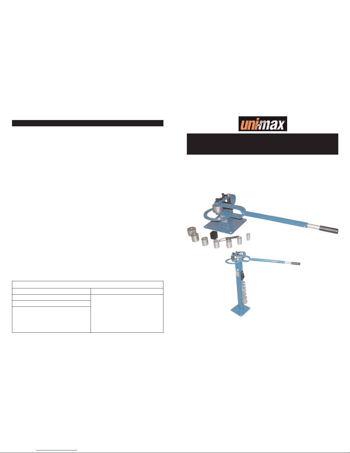
This universal bending machine with a massive steel stand that also serves as a storage place for bending
accessories, enables you to perform professional bending work of various type of metal struts and poles with
various cross cut sections (flat, square and circular). Equipped with a telescopic arm - length up to 90 cm
ensures enough power to perform your bending works. Machine is available in two options - a model with
a table mount and model with its own stand.
Accessories:
Radius bending accessories: 1“, 1 1/4“, 1 1/2“, 1 3/4“, 2“, 2 1/2“, 3“.
The accuracy of instructions, graphs and information contained herein, depends on the printing date. Due to
continuous product improvement, the manufacturer reserves the right to change technical parameters of the
product, without prior customer notification.
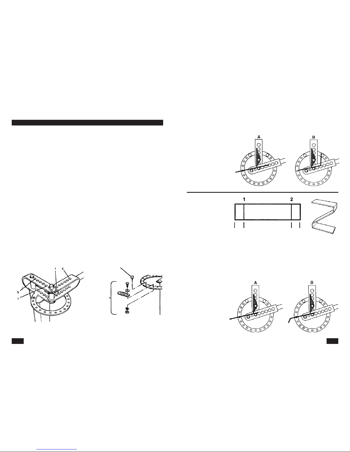
Material suitable for bending:
Hot rolled steel (steel with low carbon content)
You may bend steel with diameter up to 6.5 cm . . . . . . . . . . . . . . . . . . . . . . . . .around the centre stud.
To bend large diameters, place the master die on the centre stud. . . . . . . . . . . . . . . . . . . . . . . . . . . .2"
Maximum dimensions of the work piece
Flat steel straps . . . . . . . . . . . . . . . . . . . . . . . . . . . . . . . . . . . . . . . . . . . . . . . . . . . . . . . .8 × 50 mm
Round or square steel poles . . . . . . . . . . . . . . . . . . . . . . . . . . . . . . . . . . . . . . . . . . . . . .16 × 16 mm
EXCEPTION
Rib-reinforced pole with diameter of 12.7 mm may be bent only around the centre stud
with the 3" master die installed.
Dimension of round or square steel rod - sharp bending . . . . . . . . . . . . . . . . . . . . . . . . . . .5 × 50 mm
or . . . . . . . . . . . . . . . . . . . . . . . . . . . . . . . . . . . . . . . . . . . . . . . . . . . . . . . . . . . . . . . . . .6 × 32 mm
A pole with diameter of 12 mm may be bent around the . . . . . . . . . . . . . . . . . . . . . . . . .3" master die.
Packaging dimensions . . . . . . . . . . . . . . . . . . . . . . . . . . . . . . . . . . . . . . . . . . .900 × 250 × 270 mm
Gross weight . . . . . . . . . . . . . . . . . . . . . . . . . . . . . . . . . . . . . . . . . . . . . . . . . . . . . . . . . . . . . .26 kg
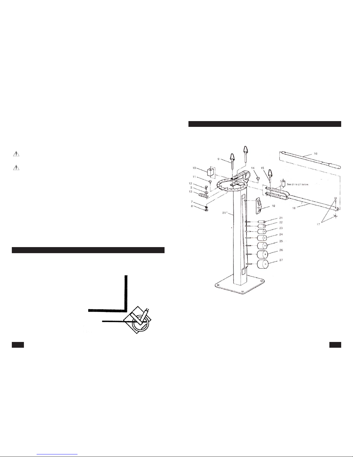
DESCRIPTION
TECHNICAL SPECIFICATION
REPAIR AND MAINTENANCE REPORT
Report and maintenance report:
DATE SERVICE SHOP
REPAIR AND MAINTENANCE REPORT

Position Description Number of pieces
1 Bracket middle piece 1
2 Screw 9.5 x 120.7 mm 1
3 Flat washer 9.5 mm 4
4 Ring assembly 1
5 Flat head screw 9.5 mm 2
6 Ring middl piece 3
7 Safety washer 9.5 mm 4
8 Nut 9.5 mm 4
9 Long connecting stud 2
10 Stopper cube 1
11 Cube support 1
12 Screw 9.5 x 28.6 mm 1
13 Moveable stopper 1
14 Non-moveable stopper 1
15 Short connecting stud 1
16 Handle extension arm 1
17 Handle stud with clamp 1
18 Handle 1
19 Sharp-angle die 1
20 Stand (only for model CB200) 1
21 Die 25.4 mm (1") 1
22 Die 31.8 mm () 1
23 Die 38.1 mm (11/2") 2
24 Die 44.5 mm (1 3/4") 1
25 Die 50.8 mm (2") 1
26 Die 63.5 mm (2 1/2") 1
27 Die 76.2 mm (3") 1
38
PART LISTING
3
???
Symbols used in this manual
Warning!
This symbol informs you about the risk of personal injury or damage to the machine
or materials.
Danger of being caught by moving machine parts!
Caution! Loose clothing or body parts may get caught by moving machine parts.
Caution!
Danger of damages!
Note:
Additional information.
Use personal protective gear.
General instructions
•Make sure you know how to control your tool or machine and that you are familiar with its operating
procedure. Know the hazards that may occur, if not used correctly.
•If other person is using this machine make sure that he knows how to safely operate this equipment and
that he is familiar with hazards and risk that may occur, if not used correctly.
•Always pay attention to safety instructions on the safety labels. Do not remove or damage them. If the
warning label becomes unreadable, please contact your vendor.
•Disorganized and dirty work shop may cause accidents.
•Never work in narrow or poorly lit rooms. Always keep stable posture.
•Maintain your tools clean.
•Handles must be kept free of grease and dirt.
•Make sure no children, unauthorized persons or animals have access to your workshop.
•Do not put legs or hands inside the working space.
•Never leave your machine unattended during operation.
•Use only for purposes for which it has been designed.
•Use personal protective gear such as safety goggles, ear protection, respirator, safe working shoes etc.
•Do not overreach, use both hands.
•Never work under the influence of alcohol or other drugs.
•Do not use the machine/tool if you feel dizzy or week.
•Any modifications or improvements to the machine are strictly prohibited. DO NOT USE if you discover
bent part, crack or other damage.
•Never perform any maintenance during operation.
•If you see any unusual sign or hear any strange sound, switch off the machine immediately.
•Always remove wrenches and screwdrivers from your machine after use.
•Before use, make sure all screws are tightened securely.
•Perform maintenance regularly. Before use make sure the machine is in good working conditions and
without any damage.
•Use only original spare parts during repairs.
•Using extension pieces or accessories not approved by the manufacturer may cause injuries to the
operating personnel.
SAFETY PRECAUTIONS

4
•Use suitable tool for particular type of work. Do not overload your machine or accessories. Do not attempt
to use machine with insufficient power to perform heavy duty work.
•Do not overload your device. Measure the work load in such way, so it could be done with comfortable
speed.
•Do not expose to extremely high temperature or direct sunlight.
•This machine is not designed for use in humid environments or under water.
Assembly
•Do not use the machine unless completely assembled.
Bending and cutting operations
•Mount your machine to a work table or to the floor to ensure stability during bending process.
•Before bending, mark the location of the fold/bend and securely fasten the work piece with the fastening
jaws.
•Always remove all obstacles from the working area.
•Make sure that enough material extends beyond the stopper cube and shaping die. That way you prevent
sudden release of the work piece and subsequently the bending handle.
•Before bending always push the connecting studs all the way in.
•Never try to attempt to bend thermally hardened materials. Only hot-rolled steel may be bent on your machine.
•NEVER attempt to modify or use other tools besides the supplied accessories. Do not use different of
extension pole for the bending handle.
•Do not use your machine for metal sheet cutting with thickness, width and strength higher than the
maximum allowed values as described in the technical parameters. Do not use for thermally processed or
hardened materials.
•To prevent injuries do not touch the gear mechanism during work.
•Do not put your hands inside the bending or cutting area.
•Make sure your machine is securely fastened to work table or to the floor. The mount of the machine must
be able to withstand the high bending forces during work.
•Example of proper installation of your machine may be seen on the picture.
•Do not install you machine in corner or close to a wall.
wall
work piece
bending machine
ASSEMBLY
37
Stand bending machine
DETAILED PART DRAWING

36
•Keep your tools clean. Dirt may enter the inner mechanism of your machine and cause damage.
•Do not use aggressive cleaning solution or paint thinners to clean the machine.
•Clean plastic parts with cloth dipped in soup water.
•Clean and lubricate metal surfaces with a cloth dipped in paraffin oil.
•If you are not using your machine, lubricate it with suitable grease and store it in a dry place to prevent
corrosion.
Lubrication
Lubricate working surfaces with suitable grease regularly.
When the operational life of your device is over, dispose off it in accordance with valid rules and regulations.
Your product is made of metal and plastic parts that may be recycled when separated.
1. Disassemble all parts.
2. Separate all parts according to the material they are made of (e.g. metals, rubber, plastics, etc.).
Take the separated parts to the recycling facility near you.
Information about the locations of recycling centres may be found at your local City office or throughout an
Internet search.
If the machine breaks down, send it back to the vendor for quick repair.
Please, enclose brief description of the defect. That makes repair easier. If the machine is still covered by
warranty, enclose the warranty card and proof of purchase receipt. After the warranty period expires, we
repair your machine for a special price.
To prevent possible damages during shipping, packed the machine carefully or use the original packaging
material. We are not liable for shipping damages due to incorrect packaging of your machine. If making
a claim at the shipping company the level and method of packaging plays a major role during claim evaluation
process.
Note: Pictures and contents in this manual may slightly differ from the actual product or accessories.
It is due to continuous improvement of our products. Such small differences have no effect on the product
functionality.
DISPOSAL
CAUTION
MAINTENANCE
5
Assembling procedure
•Connect the bent part with the round base,
using screw 3/8", flat washer, thick distance
washer (that is placed on the screws inside
the fold), thin distance washers, spring washers
and nuts.
•Place the bent part of the handle (with the holes)
inside the base fold and secure in place with
one or both long connecting studs.
•Remove the clamp from the handle stud and pull
the stud out. Pull the extension arm out, push
the stud in the inner hole and replace the clamp
back.
•Put the machine in final position, where it will
be used. Turn the handle in both directions, to
make sure that no obstacles are within the reach
of the handle.
•Make sure that there is enough space behind the machine to handle long work pieces. If you need to
place the machine close to a wall, tray to place it according to the drawing on the picture.
CAUTION: Do not use the machine if it is not securely mounted to a work table or to the floor. Severe
injuries may occur.
screw 3/8"
thick
distance
spacer flat washer
thin distance
spacer
elastic washer
nut
flat washer
elastic washer
nut
mount
stud
extension
arm
handle
safety pin
handle stud

6
Basic operation
•The most part of this manual describes procedures how to perform common work piece bending
operations. Besides information you will learn from this manual you must gain experience from trial and
error methods to become efficient in all and special bending operations.
•You will discover differences when performing various type of bending procedures such as arch bends,
sharp angle bends or if you shape material using a die.
Most common procedures
•Never try to bend material that is thicker than 6 mm around the centre stud, without the installed die,
size at least 1".
•When performing various bending operations, proceeds according to procedures depicted on the
following pictures.
General information
•Select material and its dimension according to the drawing or design.
•Select the appropriate dies (for the centre stud or the handle) that will be needed to produce the work
piece. Choose the applicable hole to fasten the handle to the bracket assembly.
•Install the stopper cube or sharp-angle die. Mount the cube support. Make sure you install the stopper
cube correctly.
•Place the work piece in the machine and secure it in place.
•Perform first bend. Check the angle and the position of the bend and proceed.
•Perform other bends and follow the same steps. Sometimes you will have to take the work piece from the
machine, turn it around or put it back backwards.
Hole identification in the moveable and non-moveable parts of the machine.
The samples included in this manual have the bracket and handle holes numbered.
OPERATION
Hole numbering
Handle holes
Non-moveable and moveable stoppers
Non-moveable
stoppers
Bracket
holes
Moveable
stoppers
35
Bend No. 1
Slide the work piece in the machine all the way to the mark No. 1 (pic. A)
and perform 80° angle bend. Check the angle.
Bend No. 2
Slide the work piece to the mark
No. 2 (pic. B) and perform 80°
angle bend. Check the angle.
Remove the stud that holds
the sharp-angle die in place.
Remove it from the machine.
Final steps
Stitch weld both parts together.
Grind and sandblast all sharp edges.
REQUIRED MATERIAL
Flat steel bar 4.8 mm,
max. width 50.8 mm.
1 flat steel bar 190.5 mm long
1 flat steel bar 114.3 mm long
BENDING PROCEDURE (flat steel bar 190.5 mm long)
Mark the locations of the bends on the 190.5 mm long bar, as shown on the picture.
Bend No. 1
Slide the work piece in the machine all the way to the mark No. 1 (pic. A)
and perform 50° angle bend. Check the angle.
Bend No. 2
Turn the work piece around and slide it to the mark No. 2 (pic. B) and perform 50° angle bend.
Remove the stud from the
sharp-angle die and remove it.
Final steps
Stitch weld the arch part to
both parts (114.3 mm long).
The upper and the lower "Z"
arm must be parallel to each
other and the distance
between them must be
152.4 mm. Grind and
sandblast all sharp edges.
25.4
mm
25.4
mm

34
REQUIRED MATERIAL
Flat steel bar thickness 4.8 mm, max. width 50.8 mm.
2 flat steel bar 342.9 mm long
BENDING PROCEDURE
The letter "W" is made from two letters "V",
welded together, similarly as the letter "M".
REQUIRED MATERIAL
Flat steel bar thickness 4.8 mm, max. width 50.8 mm.
2 flat steel bar 190.5 mm long
Setting
Mark the locations of the bends. See the picture.
Bend
Slide the work piece in the machine all the way to
the mark No. A) and bend it to achieve the outer
measurement of 6" = 152.4 mm (see the pic.).
Final steps
Stitch weld both pieced together and make sure they
are parallel to each other. Grind and sandblast all sharp edges.
REQUIRED MATERIAL
Flat steel bar thickness 4.8 mm, max. width 50.8 mm.
1 flat steel bar 241.3 mm long
1 flat steel bar 95.3 mm long
BENDING PROCEDURE (flat steel bar 241.3 mm long)
Mark the locations of the bends. See the picture.
95.3 mm
95.3 mm 95.3 mm
7
Setting the bending angle
•Depending on the desired precision, use the appropriated angle-measuring gauge.
•If you want to perform identical bends on identical work pieces (the same angle and bend position) you
may use the moveable and the non-moveable stoppers on the circle of the bracket.
•The non-moveable stopper is used if higher precision is required.
•Therefore, if you need higher precision of the angle setting, use the non-moveable stopper.
•Tighten the nut only slightly and test the bend angle.
•If everything is ok, tighten the nut firmly.
•Test the final angle on an identical piece of material. Due to the resiliency of the material the bend has
tendency to come back a little.
•After you test the angle and the bend, write all the information about the used dies, diameters and stud
positions an so on, to make setting in the future easier.
Using the stopper cube
Purpose of the stopper cube
•The cube prevents the material / work piece from
turning during die-bending around the centre stud or
if another die has been placed on the centre stud.
•Before you start bending, place and fix the stopper
cube (use the connection stud) in one of the five
large holes in the middle of the ring assembly.
(The large hole in the middle of the bracket is for
the centre stud). The hole you should use, shall be
determined based on the material thickness, nut
size, centre stud and on the position of the stopper
cube.
•You may use the cube stopper in various positions
based on the angular tilt. The cube together with the
stud can be used in 5 different holes of the rotating
part of the tool.
•The cube may be placed in various positions based
on the stud angular tilt. The positions of the stopper
cube are determined and described in the manual
with numbers. See picture on the right.
•For bending purposes you may use only four positi-
ons though. Used options in this manual are shown
on the picture.
Warning: place the stopper always to the right, away
from the centre - regardless what surface will
be touching the work piece. If you place the
cube on the left, away from the centre, the
work piece and the cube will move during the
bending process.
stopper cube
stopper cube positions
Stopper cube
Cube support placement
Cube support

8
Setting the position of the stopper cube (the correct orientation of the cube and
selection of the correct hole in the bracket):
•Connect the handle to the centre bracket stud, using the appropriate die, placed on the centre stud.
•Mount the correct die in the applicable handle hole.
•Place the work piece inside the machine. Set the handle all the way to the rear (counter-clockwise)
and place the stopper cube as close as possible to the centre stud.
IMPORTANT: Always use the hole in the bracket that will ensure that the position of the stopper cube is as
closes as possible to the centre stud or to the die and at the same time allowing you to slide
the work piece inside the machine.
•If there is too much room between the stopper cube and the centre stud or the die, turn the cube to
a different position or use hole that is closer to the centre.
Cube support placement
•The support must be placed under the stopper cube (see the picture) to be able to hold it in the centre
and in vertical position.
•Place the support in the appropriate bracket hole, to ensure the cube support and at the same time it
must not obstruct the connecting stud when pushing it in the cube hole and in the lower bracket hole.
Fastening the work piece / material
If the stopper cube is in correct position, you may
not need to fasten the work piece. But if you are
performing special bending work or need to bend
with high precision, it is good idea to fasten the work
piece to the stopper cube, using self-locking pliers
(see picture on the right).
Using sharp-angle bending accessories
The sharp-angle die is used instead of the stopper cube
when bending flat materials into right angle or other
acute angles.
Position of the die
Unlike the stopper cube this die has only one correct
position when the connecting stud is placed in the
bracket hole 3.
Cube support position
The cube support must be placed under the
sharp-angle die to be able to hold it inside the bracket
and in vertical and centred position. (Compare with
picture showing the position of the stopper cube).
Place the support in the hole number 3 inside the
bracket so it supports the device but so it does not
obstruct the connecting stud when pushing it inside
the device hole and inside the lower bracket hole.
Work piece fastening
Self-locking
pliers
sharp-angle die
sharp-angle die
Bracket holes
33
REQUIRED MATERIAL
Flat steel bar thickness 4.8 mm, max. width 50.8 mm.
1 flat steel bar 342.9 mm long
BENDING PROCEDURE
Mark the locations of the bends. See the picture.
Bend No. 1
Slide the work piece in the machine all the way to the mark No. 1 (pic. A) and perform 75° angle bend.
Bend No. 2
Slide the work piece to the mark No. 2 (pic. B) and perform 75° angle bend.
Remove the stud that holds the sharp-angle die in place. Remove it from the machine.
Final steps
Grind and sandblast all sharp edges.
152.4 mm 152.4 mm

32
Bend No. 1
Slide the work piece in the machine all the way to the mark No. 1 (pic. A)
and perform 45° angle bend. Check the angle. To make the second 45° angle
bend easier, make a mark on the ring or place a stopper there, instead of the mark.
Bend No. 2
Slide the work piece to the mark No. 2 (pic. B) and perform 45° angle bend.
Check the angle.
Bend No. 3
Turn the work piece (pic. C) and slide it to the mark No. 3 and perform 45° angle bend.
Check the angle.
Bend No. 4
Slide the work piece to the mark No. 4 (pic. D) and perform 45° angle bend.
Inspect the angle and make sure that both arms of the "U" letter are parallel to each other.
Final steps
Grind and sandblast all sharp edges.
Mark
9
Fastening the work piece / material
If you use the sharp-angle die, you do not need to fasten the work piece.
Bending process
•On the work piece, mark the location of the bend with a thin chalk.
•Place the work piece inside the machine so you can see half of the mark and the other half is covered
with the edge of the sharp-angle die.
•If you are making two right angle bends on the same side of the work piece, the distance between
the marks must be about 3 mm bigger than
the inner measurement of the finished bend.
Round pole bending
REQUIRED MATERIAL (only for this sample)
One piece of pole rod with length 228.6 mm and
diameter of 15.9 mm.
Too flat pieces with desired dimensions.
NOTE: if you are to make similar handles with different dimensions,
you must first test, which die size and what position of the cube best fits your design.
•Using the long connection stud, connect the handle brackets and rings through their centre hole
(for the centre stud). Place 25.4 mm (1") die on the stud.
•Using the short connecting stud mount the 50.8 mm (2") die in the handle hole 2).
•Mount the stopper cube on the long connecting stud in position as shown on the picture A).
•Place the pole rod inside the machine, so it is protruding 50.8 mm (2") beyond the die on the centre stud
(see picture B) and perform 90° angle bend.
•Turn the work piece around around according to picture C and make the second 90° bend.
Then remove the work piece from the machine.
•Drill holes with diameter 15.9 mm in the base mounts and place the handle inside the holes halfway.
NOTE: always drill holes with diameter equal to the diameter of the rod pole handle.
•Weld the anchoring mount to the handle at the back. Grind and finish the finished weld join flat.
TYPICAL HANDLE MADE FROM POLE ROD
AND TWO FLAT ANCHORING MOUNTS
4 position
die 50.8 mm (2")
die 25.4 mm (1")
50.8 mm
(2")
50.8 mm (2")

10
Flat steel handle
REQUIRED MATERIAL
One piece of flat, hot-rolled steel bar.
length 228.6 mm,
cross section 25.4 x 4.8 mm.
NOTE: If you are to make similar handles with different dimensions, you must first find the location of the bends.
•Mount the sharp-angle die.
•Mark the location of the bend on the work piece with
a chalk according to the bending procedure. Markings
1 and 2 are placed on one side of the work piece and
markings 3 and 4 on the other side of the work piece.
•Place the flat rod in the machine all the way to
the marking 1 (in accordance with the picture A
and make 90° bend. Before continuing to work,
check the bend for accuracy.
•Set the moveable stopper so every bend
produces 90° angle.
•Turn the work piece around, according to the
picture. B and slide it to the marking 2 and
perform 90° angle bend.
•Turn the work piece around according to picture
C and slide it towards the marking 3 and
perform 90° angle bend.
•Place the work piece in accordance with picture D
and slide it to the marking 4 and perform 90° angle bend.
•Grind and sandblast all sharp edges.
Making various pipe holders
Simple pipe holder
REQUIRED MATERIAL
To manufacture a pipe holder with inner diameter
of 25.4 mm (to hold a pipe with outer diameter of
25.4 mm) use flat, hot-rolled steel bar with length
114.3 mm and with cross-section 25.4 x 4.8 mm.
NOTE: if you are to make similar holder with
different dimensions, you must first test,
which die size and what position
of the cube best fits your design.
Using the long connection stud,
connect the handle brackets and
rings through their centre hole (for
the centre stud). Place 25.4 mm (1")
die on the stud.
TYPICAL HANDLE MADE FROM FLAT STEEL BAR
BENDING PROCEDURE
38.1 mm 38.1 mm 38.1 mm38.1 mm
TYPICAL PIPE HOLDERS
simple holder
double holder
1 3/4" - 44.5 mm
Position
2
Die
38.1 mm
(1 1/2")
Non-moveable stopper
Die 25.4 mm (1")
31
REQUIRED MATERIAL
Flat steel bar thickness 4.8 mm, max.
width 50.8 mm.
1 flat steel bar 152.4 mm long
1 flat steel bar 147.6 mm long
BENDING PROCEDURE (flat steel bar 147.6 mm long)
Mark the locations of the bends on the 147.6 mm long bar, as shown on the picture.
Bend No. 1
Slide the work piece in the machine all the way to the mark No. 1 (pic. A) and perform 45° angle bend.
Check the angle. To make the second 45° angle bend easier, make a mark on the ring or place a stopper
there, instead of the mark.
Bend No. 2
Turn the piece around
(see picture. B) and slide it toward
the mark No. 2 and perform 45°
angle bend. Check the angle.
Final steps
Stitch weld both parts together.
Grind and sandblast all sharp
edges.
REQUIRED MATERIAL
Flat steel bar thickness 4.8 mm, max. width 50.8 mm.
1 flat steel bar 374.6 mm long
BENDING PROCEDURE
Mark the locations of the bends. See the picture.
25.4
mm
25.4
mm
31.8
mm 127 mm
127 mm 31.8
mm
Mark

30
Bend No. 7
Slide the work piece to the mark No. 7 (pic. G) and perform 41° angle bend.
Check the angle.
Bend No. 8
Slide the work piece to the mark No. 8 (pic. H) and perform 45° angle bend.
Bend No. 9
Turn the piece around (see picture. I).
Remove the sharp-angle die stud to make room for the work piece,
slide the work piece in the machine and place the stud back again.
Slide the work piece to the mark No. 9 and perform 45° angle bend. Check the angle.
Bend No. 10
Turn the work piece around again (pic. J) and move it to the mark No. 10 and perform 45° angle bend.
Inspect the angle. Also make sure that the lower and the upper part of the letter "S" are parallel to
each other.
11
•Using the short connecting stud mount the 38.1 mm (1 1/2") die in the handle hole 2).
•Using the long connecting stud, mount the stopper cube (as shown on picture A).
•Place the flat steel in your machine so the end of the work piece extends 44.5 mm beyond the die on the
centre stud (see picture B).
•Fasten the work piece to the stopper cube wit self-locking pliers.
•Perform the first bend. Turn the handle till the handle die leaves the end of the material.
•Remove the stopper cube and both dies. Change the handle connection and fix the sharp-angle die (see picture C).
•Slide the work piece as far as possible (against the centre stud).
•Place the stopper stud in the sixth hole of the ring (counting from the closed ring end clockwise).
•Turn the handle and perform the second bend at a distance of around 3.2 mm form the stopper stud.
Double holder
REQUIRED MATERIAL
To manufacture a pipe holder with inner diameter of 25.4 mm (to
hold a pipe with outer diameter of 25.4 mm) use flat, hot-rolled steel
bar with length 165.1 mm and with cross-section 25.4 x 4.8 mm.
NOTE: if you are to make similar holder with different dimensions,
you must first test, which die size and what position of the cube
best fits your design.
Using the long connection stud, connect the handle brackets
and rings through their centre hole (for the centre stud).
Place 25.4 mm (1" ) die on the centre stud.
•Using the short connecting stud mount the 38.1 mm (1 1")
die in the handle hole 2).
•Using the long connecting stud, mount the stopper cube
(as shown on picture. A).
•Place the flat steel in your machine so the end of the work
piece extends 44.5 mm beyond the die on the centre stud
(see picture. B).
•Perform the first bend. Turn the handle till the handle die leaves
the end of the material.
Turn the work piece around according to picture C and place it in
the machine so the other end is extending beyond the die on the centre stud by 44.5 mm.
Position 2
13
/
4
" - 44.5 mm
Die
38.1 mm
(11
/
2
")
Die 25.4 mm (1")
Non-moveable
stopper

12
•Perform the second bend. Turn the handle till the handle die leaves the end of the material.
•Remove the stopper cube and fix the sharp-angel die.
•Temporarily remove the centre stud and place the work piece in the machine and slide it as far as
possible (against the centre stud) see picture D).
•Place the stopper stud in the sixth hole of the ring (counting from the closed ring end clockwise).
•Turn the handle and perform the third bend at a distance of around 3.2 mm form the stopper stud.
•Turn the work piece around around (picture E) and move it as far as possible to the left, against the centre
stud. Temporarily remove the centre stud, so you can slide the work piece in the machine.
•Turn the handle and perform the fourth bend at a distance of around 3.2 mm form the non-moveable
stopper stud.
Anchoring bolts bending
REQUIRED MATERIAL
Anchoring bolt manufacture with length of 254 mm
from pole 311.2 mm long.
NOTE: To manufacture bolt of different length, use
shorter or longer pole (the pole must be long
enough so the cube can grip it firmly).
Use the long connecting stud to fasten the handle
brackets and the rings through the centre stud hole.
Place 25.4 mm (1" ) die on the centre stud.
•Using the short connecting stud mount the 50.8 mm (2") die in the handle hole ( 2).
•Mount the stopper cube with the connecting rod and place and turn it according to the work piece
diameter: position 2 for 9.5 mm screws or 12.7; position 4 for screws 15.9 mm.
•Slide the work piece in the machine so the end of the thread extends the stopper cube:
12.7 mm for screws 9.5 mm, 15.9 mm for screws 12.7 mm and 6.4 mm for screws 15.9 mm.
•Turn the handle till you reach 90° angle between the shank of the screw and the anchoring part.
TYPICAL BRACKET AND ANCHORING BOLTS
Anchoring bolt
Bracket bolt
Position of
the stopper cube in
the following text
Material protrusion in the following text
Die 50.8 mm (2")
Die 25.4 mm (1")
Bend No. 3
Slide the work piece to the mark No. 3 (pic. C)
and perform 41° angle bend. Check the angle.
Bend No. 4
Slide the work piece all the way to the mark No. 4
(pic. D) and perform 45° angle bend.
Bend No. 5
Turn the work piece around (pic. E and move it to
the mark No. 5 and perform 45° angle bend.
Check the angle.
Bend No. 6
Slide the work piece to the mark No. 6 (pic. F)
and perform 45° angle bend.
Check the angle.
29

28
REQUIRED MATERIAL
Flat steel bar thickness 4.8 mm, max. width 50.8 mm.
1 flat steel bar 225.4 mm long
1 flat steel bar 152.4 mm long
1 flat steel bar 79.4 mm long
BENDING PROCEDURE
Make the letter "P" part according to
the steps described earlier.
Final steps
Stitch weld the 79.4 mm long piece to
the letter "P" as shown on the picture.
Grind and sandblast all sharp edges.
REQUIRED MATERIAL
Flat steel bar thickness 4.8 mm, max. width 50.8 mm.
1 flat steel bar 419.1 mm long
CAUTION: due to the high number of bends required to produce the letter "S",
make sure to inspect all angles before going any further.
BENDING PROCEDURE
Mark the locations of the bends. See the picture.
Caution. Five marks must be done on side of the work piece
and the remaining five on the other side of the work piece.
Observe the picture.
Bend No. 1
Slide the work piece in the machine all the way to the mark
No. 1 (pic. A) and perform 45° angle bend. Check the angle.
To make the second 45° angle bend easier, make a mark on
the ring or place a stopper there, instead of the mark.
(On marks 3 and 7 you must produce an angle 3 of 41°).
Bend No. 2
Slide the work piece to the mark No. 2 (pic. B) and perform
45° angle bend.
79.4 mm
25.4
mm
25.4
mm
25.4
mm
25.4
mm
25.4
mm
25.4
mm
31.8
mm 66.7 mm66.7 mm
Mark
13
Bracket screw bending
The following charts show the applicable settings for bracket screw manufacture with typical end length and
bent radius manufactured from steel poles of common diameters.
The lower picture shows the settings for bracket screw manufacture with length of 88.9 mm and inner
measurement of 50.8 mm, from steel pole with diameter of 15.9 mm. To manufacture different sizes, set the
die size and the position of the stopper cube according to the charts.
Length
To manufacture long bracket screws add double the required length to the specified pole length (for example;
to make bracket screws that is 25.4 mm longer, add 50.8 mm to the pole length).
Bending radius
You may choose from 8 different radiuses, by choosing from seven different dies or you may use the centre
stud with no die. To prevent damage or bending of the centre stud, always use shaping die if you are shaping
material with diameter above 9.5 mm.
Notes
•Because the metallurgical structure and the dimensions of the pole may slightly change throughout its
length, we recommend performing test bend before making large amount of bracket screws.
•Write down the die sizes and the positions of the stoppers you already used to manufacture a certain
product to make future setting easier.
Typical settings to manufacture bracket screws from pole rods
(for detailed information see the following charts)
Stopper
cube position
stopper cube
distance
Centre stud die
Handle die

14
27
REQUIRED MATERIAL
Flat steel bar thickness 4.8 mm, max. width 50.8 mm.
1 flat steel bar 355.6 mm long
1 flat steel bar 98.4 mm long
BENDING PROCEDURE
Make the letter "C" from the 355.6 mm
long piece according to the procedure
described earlier.
Final steps
Stitch weld both parts together.
Grind and sandblast all sharp edges.
REQUIRED MATERIAL
Flat steel bar thickness 4.8 mm, max. width 50.8 mm.
1 flat steel bar 225.4 mm long
1 flat steel bar 152.4 mm long
BENDING PROCEDURE
Make the letter "B" parts - the straight and the arch piece.
Final steps
Stitch weld both parts together.
Grind and sandblast all sharp edges.
REQUIRED MATERIAL
Flat steel bar thickness 4.8 mm, max. width 50.8 mm.
1 flat steel bar 355.6 mm long
1 flat steel bar 98.4 mm long
1 flat steel bar 50.8 mm long
1 flat steel bar 19.1 mm long
BENDING PROCEDURE
Make the letter "O"
(see the procedure described above).
Final steps
Stitch weld the short pieces to the letter
"O" as shown on the picture. Grind and
sandblast all sharp edges.
19.1 mm
50.8 mm

26
REQUIRED MATERIAL
Flat steel bar thickness 4.8 mm, max. width 50.8 mm.
2 flat steel bar 342.9 mm long
BENDING PROCEDURE
Make two letters "V" according to steps described on page 36.
Final steps
Place both "V" parts together according to the picture and stitch
weld them together. Make sure all three lower ends are properly
aligned. Grind and sandblast all sharp edges.
REQUIRED MATERIAL
Flat steel bar thickness 4.8 mm, max. width 50.8 mm.
1 flat steel bar 204.8 mm long
1 flat steel bar 152.4 mm long
BENDING PROCEDURE (flat steel bar 204.8 mm long)
Mark the locations of the bends on the 204.8 mm long bar,
as seen on the picture.
Bend No. 1
Slide the work piece in the machine all the way to the
mark No. 1 (pic. A) and perform 73° angle bend. Check
the angle. Remove the stud that holds the sharp-angle die
in place. Remove it from the machine.
Bend No. 2
Turn the piece (see picture. B) and slide it toward the mark No. 2
and perform 73° angle bend. Check the angle. Remove the stud
that holds the sharp-angle die in place. Remove it from the
machine.
Final steps
Stitch weld both parts together. Make sure the vertical arms are
parallel to each other. Grind and sandblast all sharp edges.
25.4
mm
25.4
mm
15
Letter manufacturing / bending (for headings and signs)
On these following pages you will find instructions how to make all 26 letters of the Alphabet (typical font):
•flat steel bar, thickness 4.8 mm
•height 152.4 mm
•width (depth) 50.8 mm
Notes:
•To manufacture letters, use hot-rolled steel - not thermally hardened.
•Follow these steps exactly and in the same sequence. Pay extra attention when making the letter "S",
the most difficult to shape.
•To gain experience and not to waste material, try to manufacture few letters from a flat steel bar with
thickness of 4.8 mm and width 12.7 mm.
•If you have to manufacture two or more identical letters, make them first and then move on to manufacture
others.

16
REQUIRED MATERIAL
Flat steel bar thickness 4.8 mm, max. width 50,8 mm.
1 bar length 355.6 mm
1 bar length 88.9 mm.
BENDING PROCEDURE
•Mark the locations of the bends on the bar along its entire length,
as seen on the picture.
Bend No. 1
•Slide the work piece in the machine all the way to the mark No. 1 (pic. A) and perform 76° angle bend.
Check the angle and move on to make the other bend.
Bend No. 2
•Slide the work piece in the machine all the way to the mark No. 2 (pic. B) and perform 76° angle bend.
Inspect the angle.
•Remove the stud that holds the sharp-angle die in place. Remove it from the machine.
Final steps
•Place a piece 88.9 mm long between the arms of the letter "A" and make sure it is parallel with the upper
edge and stitch weld it together.
•Grind and sandblast all sharp edges.
152.4 mm 152.4 mm
25
REQUIRED MATERIAL
Flat steel bar thickness 4.8 mm,
max. width 50.8 mm.
1 flat steel bar 177.8 mm long
1 flat steel bar 152.4 mm long
1 flat steel bar 63.5 mm long
BENDING PROCEDURE (flat steel bar 177.8 mm long)
Mark the locations of the bends. See the picture.
Bend
Slide the work piece to the machine all the way to
the mark. Perform bend to achieve distance
of 152.4 mm. Observe the picture.
Final steps
Stitch weld both pieces together as seen
on the picture. Make sure that the outer
ends of the bent piece have the same
distance from the straight arm.
Grind and sandblast all sharp edges.
REQUIRED MATERIAL
Flat steel bar thickness
4.8 mm, max. width 50.8 mm.
1 flat steel bar 263.5 mm long
BENDING PROCEDURE
Mark the locations of the bends. See the picture.
Bend No. 1
Slide the work piece in the machine all the way to the mark No. 1
and perform 45° angle bend. Check the angle.
Bend No. 2
Slide the work piece to the mark
No. 2 and perform 90° angle bend.
Check the angle. Remove the stud
that holds the sharp-angle die in
place. Remove it from
the machine.
Final steps
Grind and sandblast all sharp edges.
88.9 mm
flat steel bar 177.8 mm
84.1 mm 31.8
mm

24
REQUIRED MATERIAL
Flat steel bar thickness 4.8 mm, max. width 50.8 mm.
1 flat steel bar 254.0 mm long
BENDING PROCEDURE
Mark the locations of the bends. See the picture.
Bend No. 1
Slide the work piece in the machine all the way to the mark
No. 1 (pic. A) and perform 45° angle bend. Check the
angle and move on to make the following bend. To make
the second 45° angle bend easier, make a mark on the
ring or place a stopper there, instead of the mark.
Bend No. 2
Slide the work piece in the machine all the way to the
mark No. 2 (pic. B) and perform 45° angle bend.
Check the angle.
Bend No. 3
Slide the work piece to the mark No. 3 (pic. C) and
perform 45° angle bend. Check the angle. Remove
the stud that holds the sharp-angle die in place.
Remove it from the machine.
Final steps
Grind and sandblast all sharp edges.
31.8
mm
63.5 mm
31.8
mm
Mark
17
REQUIRED MATERIAL
lat steel bar thickness 4.8 mm,
max. width 50.8 mm.
1 bar length 225.4 mm
1 bar length 152.4 mm
BENDING PROCEDURE
Using a chalk, mark the bend location on both flat rods (length 225.4 mm). See the picture.
Bend No. 1
Slide the work piece in the machine all the way to the mark
No. 1 (pic. A) and perform 45° angle bend. Check the angle
and move on to make the other bend. To make the second
45° angle bend easier, make a mark on the ring or place
a stopper there, instead of the mark.
Bend No. 2
Slide the work piece in the machine all the way to the mark
No. 2 (pic. B) and perform 45° angle bend. Inspect the angle.
Bend No. 3
Turn the piece (see picture C) and slide it to the mark No. 3
and perform 45° angle bend. Check the angle.
Bend No. 4
Turn the work piece around according to picture D and move
it to the mark No. 4 and perform 45° angle bend. Check the
angle. Remove the stud that holds the sharp-angle die in
place. Remove it from the machine.
Final steps
Stitch weld both "U" pieces together. Then weld the
152.4 mm long part (the back side of the letter "B") to the
welded pieces. Grind and sandblast all sharp edges.
Two pieces
with length of
225.4 mm
152.4 mm
25.4 mm
25.4 mm 69.9
mm
69.9
mm
Mark

18
REQUIRED MATERIAL
Flat steel bar 4.8 mm,
max. width 50.8 mm.
1 bar length 355.6 mm
BENDING PROCEDURE
On the long piece (length 355.6 mm), make the bend markings as seen on the picture.
Bend No. 1
Slide the work piece in the machine all the way to the mark
No. 1 (pic. A) and perform 45° angle bend. Check the angle
and move on to make the following bend. To make the
second 45° angle bend easier, make a mark on the ring
or place a stopper there, instead of the mark.
Bend No. 2
Slide the work piece to the mark No. 2 (pic. B) and perform
45° angle bend. Check the angle.
Bend No. 3
Slide the work piece to the mark No. 3 (pic. C)
and perform 45° angle bend. Check the angle.
Bend No. 4
Turn the piece (see picture D and move
it to the mark No. 4 and perform 45°
angle bend. Check the angle.
63.5 mm 31.8
mm
31.8
mm
63.5 mm
31.8
mm
31.8
mm
Mark
23
REQUIRED MATERIAL
Flat steel bar thickness 4.8 mm, max. width 50.8 mm.
2 flat steel bar 152.4 mm long
1 flat steel rod 95.3 mm long
Final steps
Weld it together as seen on the
picture. Make sure to check the 90°
angle between both arms. Grind
and sandblast all sharp edges.
76.2 mm
REQUIRED MATERIAL
Flat steel bar thickness 4.8 mm,
max. width 50.8 mm.
2 flat steel bar 127 mm long
1 flat steel bar 142.9 mm long
BENDING PROCEDURE (flat steel bar 127 mm long)
Mark the locations of the bends on both bars (127 mm), as seen on the picture.
Bend No. 1
Slide the work piece in the machine all the way to the mark No. 1 and perform 45° angle bend.
Check the angle. To make the second 45° angle bend easier, make a mark
on the ring or place a stopper there, instead of the mark.
Bend No. 2
Turn the work piece around (picture B) and slide
it toward the mark No. 2 and perform 45° angle
bend. Check the angle. Remove the stud that
holds the sharp-angle die in place.
Remove it from the machine.
Final steps
Stitch weld the 142.9 mm long piece
between the arches (see the picture).
Make sure that 90° angle is correctly
set between both pieces. Grind and
sandblast all sharp edges.
31.8
mm
76.2 mm
76.2 mm
31.8
mm
Mark

22
REQUIRED MATERIAL
Flat steel bar thickness 4.8 mm, max. width 50.8 mm.
1 flat steel rod 263.5 mm long
1 flat steel rod 63.5 mm long
BENDING PROCEDURE
Make the letter "L" according to instructions below.
Final steps
Place the long piece (3" = 63.5 mm long) to a position
as shown on the picture and stitch weld it in place.
Grind and sandblast all sharp edges.
REQUIRED MATERIAL
Flat steel bar thickness 4.8 mm, max. width 50.8 mm.
1 flat steel bar 355.6 mm
1 flat steel bar 76.2 mm
BENDING PROCEDURE
Make the letter "C" according to the procedure described earlier.
Bend
Slide the long piece (76.2 mm) to the machine all the way
to the chalk mark and perform 90° angle bend. Check the
angle. Remove the stud that holds the sharp-angle die in
place. Remove it from the machine.
Final steps
Place the long piece (76.2 mm long) to a position as
shown on the picture and stitch weld it in place.
Grind and sandblast all sharp edges.
25.4
mm
19
Bend No. 5
Slide the work piece to the mark No. 5 (pic. E) and perform 45° angle bend. Check the angle.
Bend No. 6
Slide the work piece to the mark No. 6 (pic. F) and perform 45° angle bend. Check the angle.
Remove the stud that holds the sharp-angle die in place. Remove it from the machine.
Final steps
Grind and sandblast all sharp edges.
REQUIRED MATERIAL
Flat steel bar thickness 4.8 mm, max. width 50.8 mm.
1 flat steel rod 317.5 mm long.
1 flat steel rod 152.4 mm long
BENDING PROCEDURE
On the long piece (length 317.5 mm), make the bend markings as seen on the picture.
152.4 mm
31.8
mm
76.2
mm
31.8
mm
76.2
mm

20
Bend No. 1
Slide the work piece in the machine all the way to
the mark No. 1 (pic. A) and perform 45° angle bend.
Check the angle and move on to make the following
bend. To make the second 45° angle bend easier, make
a mark on the ring or place a stopper there, instead of
the mark.
Bend No. 2
Slide the work piece to the mark No. 2 (pic. B) and
perform 45° angle bend. Check the angle. Remove the
work piece from the machine and check the 90° angle
between the bent arm and the front side of the letter.
Bend No. 3
Turn the piece (see picture. C) and slide it to the mark
No. 3 and perform 45° angle bend. Check the angle.
Bend No. 4
Slide the work piece to the mark No. 4 (pic. D) and
perform 45° angle bend. Inspect the angle and make
sure that both arms are parallel to each other.
Remove the stud that holds the sharp-angle die in place.
Remove it from the machine.
Final steps
Stitch weld the long piece, (the back side of the
letter "D", 152.4 mm long) to the finished arch.
Grind and sandblast all sharp edges.
Mark
21
REQUIRED MATERIAL
Flat steel bar thickness 4.8 mm, max. width 50.8 mm.
1 flat steel rod 369.9 mm long
1 flat steel rod 63.5 mm long
BENDING PROCEDURE
On the long piece (length 369.9 mm), make the bend markings as seen on the picture.
Bend No. 1
Slide the work piece in the machine all the way to the mark No. 1 (pic. A) and perform 45° angle bend.
Check the angle and move on to make the following bend.
Bend No. 2
Slide the work piece to the mark No. 2 (pic. B) and perform 90°
angle bend. Check the angle.
Bend No. 3
Turn the piece (see picture. C) and slide it to the mark No. 3 and
perform 45° angle bend. Check the angle.
Bend No. 4
Slide the work piece to the mark No. 4 (pic. D) and perform 90°
angle bend. Inspect the angle and make sure that the upper and
the lower arm of the letter "E" are parallel to each other. Remove
the stud that holds the sharp-angle die in place. Remove it
from the machine.
Final steps
Stitch weld the middle piece (63.5 mm long)
to the middle of the letter "E". Grind and
sandblast all sharp edges.
82.6 mm 63.5 mm
31.8
mm
31.8
mm
82.6 mm
This manual suits for next models
1
Table of contents
Other Unimax Cutter manuals