From the library of: Superior Sewing Machine & Supply LLC
Each
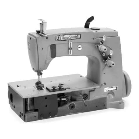
UNION
SPECIAL
machine
is
identified
by
a Style
number,
which
on
this
machine
Class,
is
stamped
into the Style plate affixed to the right front of
machine.
Serial
number
is
stamped
into
bed
casting
at
the
left
rear base of machine.
NOTE:
Instructions
stating
direction or location,
such
as
right,
left,
front or
rear
of
machine, are given
relative
to the operator's position
at
the
machine, unless otherwise noted.
The
handwheel
rotates counterclockwise in
operating direction
when
viewed
from
the
right
end
of
machine.
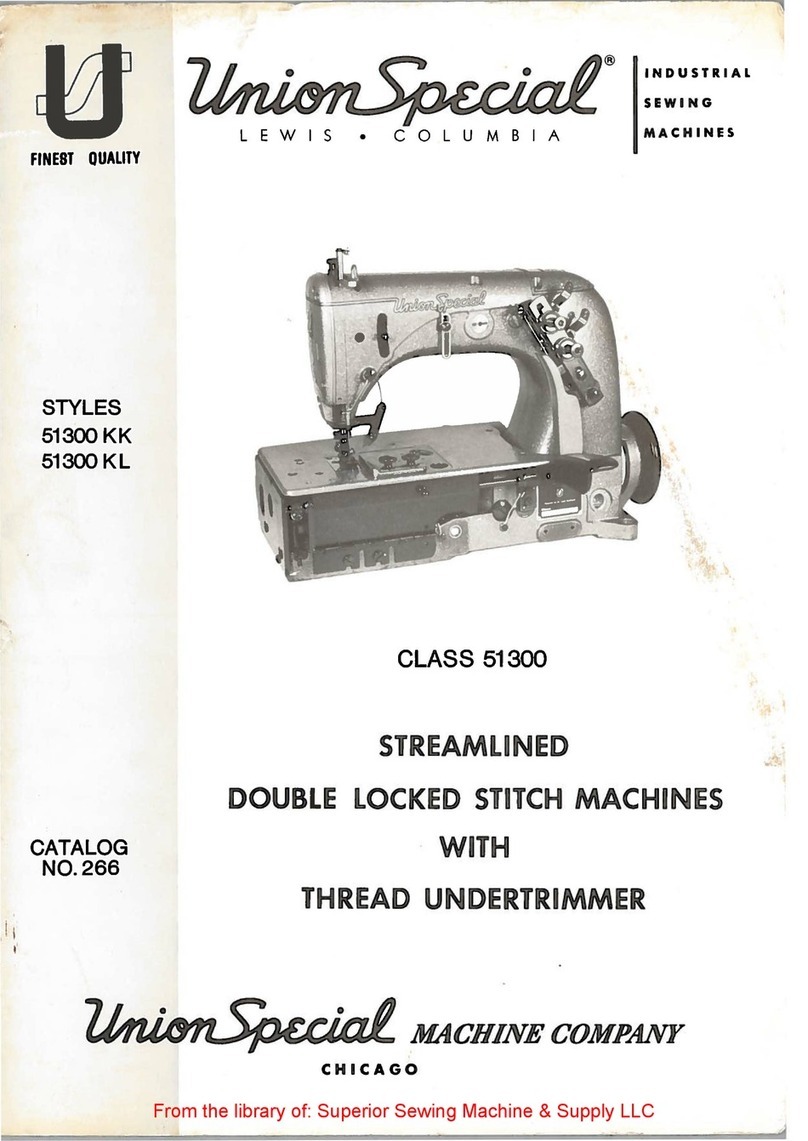
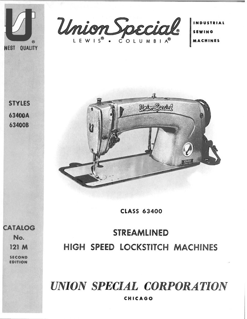
STYLES
OF
MACHINES
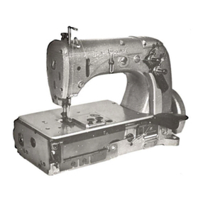
High
speed,
maximum
performance, double locked
stitch,
plain feed flatbed
machine.
Totally enclosed feed
and
looper drive
mechanism,
fully
automatic forced feed
lubricating system with
easily
replaceable
oil
filter,
quick
stitch
change,
independently driven rear needle guard
and
quick adjustable looper avoid.
LF611KlOOHM
Single needle,
HIGH
sewing
capacity
machine
with
sewing
parts to
accomodate
Selvage
Edge
Binder -for binding mattress
ticks
made
from
medium
heavy
to
heavy
weight materials.
Uses
selvage
edge
binding 5/8, 3/4
and
7/8 inch (15.8, 19.0
and
22.2mm)
wide
to
produce a 5/16, 3/8
and
7/16 inch (7.9, 9.5
and
11.1mm)
finish.
Standard
recommended
needle
Type
128
GAS,
Size 125/049.
Stitch
range
5-14
S.P.I.
Maximum
recoR111ended
speed
6500
R.P.M.
LF611KlOOMF
Single needle,
MEDIUM
sewing
capacity
machine
with
low
inertia
presser foot, permitting 1ight presser foot pressure
for
positive
feeding
and
chaining
at
high speeds -
for
long
seams
on
light
to
medium
weight fabrics
such
as in trousers,
skirts,
coats, jackets,
etc.
Standard
recommended
needle
Type
128
GBS,
Size 90/036. Stitch
range
7-10
S.P.I.
Maximum
recommended
speed
6500
R.P.M.,
depending
on
operation.
LF611K100MG
Single needle,
MEDIUM
sewing
capacity
machine
used
for side
and
inseaming men's
work
and
dress pants
made
from
medium
weight
material. Standard
recommended
needle
Type
128
GBS,
Size 90/036.
Stitch
range
10-14
S.P.I.
Maximum
recommended
speed
6500
R.P.M.,
depending
on
operation.
LF611KlOOMR
Same
as Style
LF611KlOOMF
except -
fitted
with feeding presser foot
with yielding section to
left,
allowing crossing of
seams
and
pockets.
LF611KlOOMW
Same
as Style
LF611KlOOMF
except -
used
for
seaming
cotton, flannel
and
leather
palm
gloves. Standard
recommended
needle
Type
128
GAS,
Size 110/044.
Stitch
range
5-14
S.P.I.
LF611KlOOMAW
Same
as Style
LF611K100MF
except -equipped with
narrow
feeding
presser foot
and
related
sewing
parts for 3/16 inch
(4.8mm)
margin.
LF611K112MF
Same
as Style
LF611K100MF
except -equipped with
Power
"AIR-KLIPP
®"
chain
cutter.
LF611K112MG
Same
as
Style
LF611K100MG
except -equipped with
Power
"AIR-KLIPP"
chain
cutter.
®
"AIR-KLIPP"
is
a registered trademark of
Union
Special Corporation.
3
