Uniphone ISDK-616 User manual

Uniphone ISDK-616
Digital Key Telephone System
INSTALLATION AND PROGRAMMING MANUAL
Uniphone Telecommunication Co., Ltd.

TAB LE OF CONTENTS
1. SYSTEM SPECIFICATIONS AND INSTALLATION....................................................................................1
1.1 System Specifications..................................................................................................................................1
1.2 Interface Specifications................................................................................................................................1
1.2.1 F0638 TRK/STA Card (TRK3STA8) .................................................................................................1
1.2.2 F0610 Multi-Function Card...................................................................................................................2
1.2.3 F0658 DSP Card ....................................................................................................................................2
1.2.4 Doorphone Voice Card...........................................................................................................................2
1.3 KSU Installation Instructions.......................................................................................................................2
1.3.1 ISDK-616 KSU installation steps:.........................................................................................................2
1.3.2 Choose Main Power Supply: .................................................................................................................3
1.3.3 External Battery Installation:.................................................................................................................3
1. 3.4 The Cautions For Connection:..............................................................................................................3
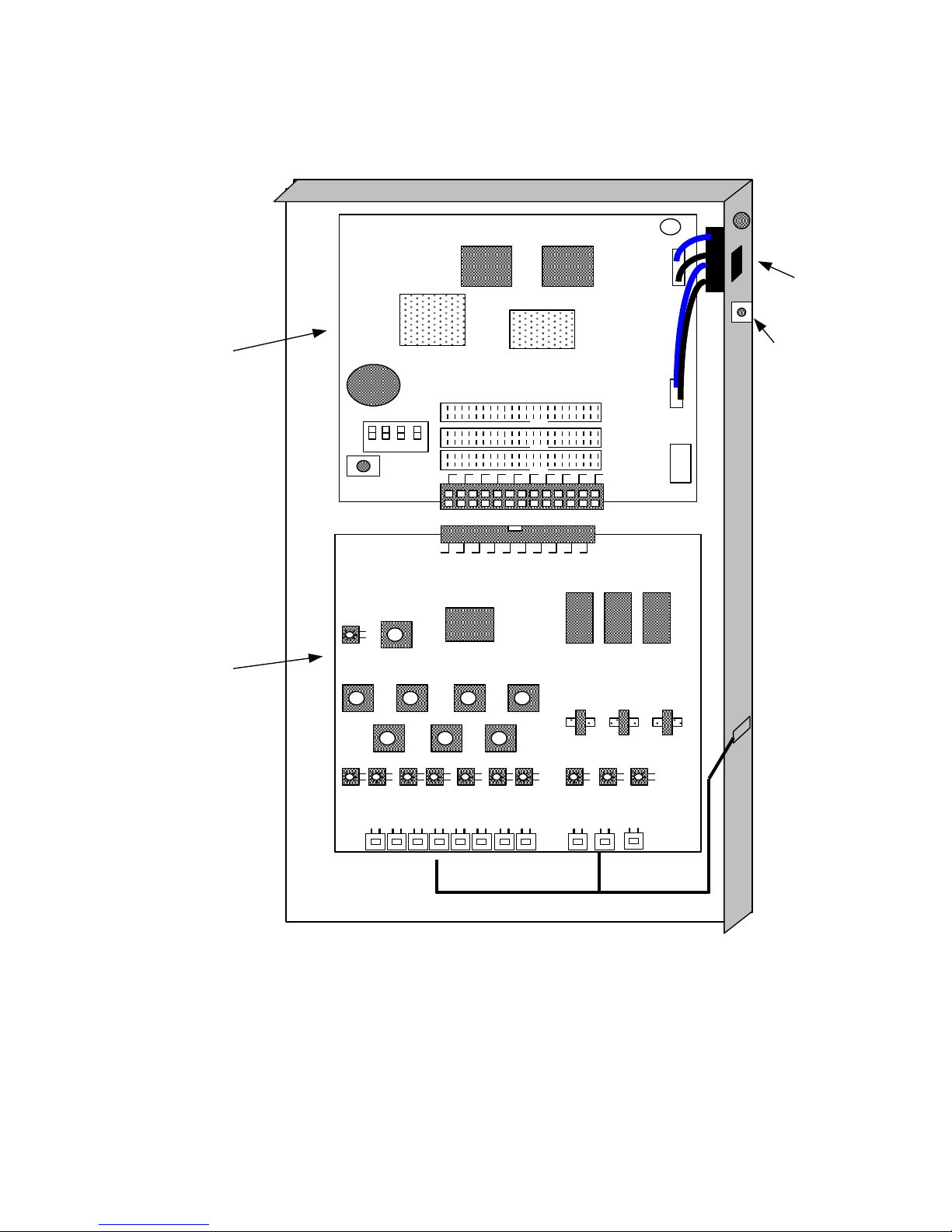
1.4 ISDK-616 System Connection Figure.........................................................................................................4
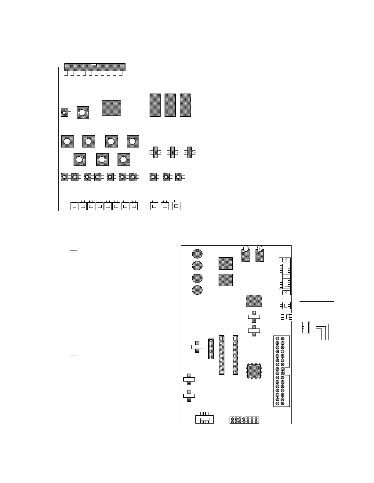
1.5 F0601 ISDK-616 CPU Card Connecting Instruction:.................................................................................5
1.6 F0658 DSP Card ..........................................................................................................................................5
1.7 F0638 TRK/STA Card (TRK3/STA8) .........................................................................................................6
1.8 F0610 Multi-Function Card.........................................................................................................................6
1.9 F0611 Doorphone Voice Card......................................................................................................................7
2. PROGRAMMING GUIDE...............................................................................................................................8
2.1 PROGRAMMING INSTRUCTION ...........................................................................................................8
2.2 Programming Clear Mode: ..........................................................................................................................8
2.2.1 Method 1 –Enter the programming clear code in 15 minute after turn on the power...........................8
2.2.2 Method 2 –By DIP switch.....................................................................................................................8
2.3 Programming Setup Mode:..........................................................................................................................8
2.3.1 The meaning of each function key for programming ............................................................................9
2.4 SYSTEM PROGRAM : Kind 1.................................................................................................................10
Kind 1 (11-22)...............................................................................................................................................11
Kind 1 (23-36)...............................................................................................................................................12
Kind 1 (37-46)...............................................................................................................................................13
Kind 1 (47-59)...............................................................................................................................................14
Kind 1 (60-73)...............................................................................................................................................15
Kind 1 (72-88)...............................................................................................................................................16
Kind 1 (89-106).............................................................................................................................................17
Kind 1 (107-121)...........................................................................................................................................18
Kind 1 (122-135)...........................................................................................................................................19
Kind 1 (141-143)...........................................................................................................................................20
2.5 STATION LINE PROGRAM : Kind 2......................................................................................................21
2.12 Built-In DISA (DSP) : Kind 9..................................................................................................................22
Kind 9 (149-52).............................................................................................................................................23
Setting item of working mode (00-05)..........................................................................................................24
Setting item of working mode (06-10)..........................................................................................................25

1
1. SYSTEM SPECIFICATIONS AND INSTALLATION
1.1 System Specifications
MODEL
ISDK-616
KSU
Power Source
DC 30V/ 2A
Power Consumption (except stations)
3W
External Back-up Battery
24V/4 –50AH
Max. Battery Charge Current
27. 6V/0.3A
Station Capacity
8–18
CO Lines
3 –6
Digital Key Telephone
8 –16
Single Line Telephone
0 –2
Switching System
PCM / TDM
Link Block
No Blocking
Tone Voice Source
Programmable Digital Voice Source
System Control
Stored Program Control
Speed Dialing (Max. 32 code) Number
System + Individual = 2000
Dimension (mm)
320 x 220 x 90
Basic Cabinet Net Weight (kg)
1.2
Key phone
Dimension (mm)
170 x 230 x 100
Net Weight (kg)
0.9
Installation
Environment
Available Temperature
5 –45°C
Relative Humidity
20 –80 %RH
1.2 Interface Specifications
1.2.1 F0638 TRK/STA Card (TRK3STA8)
Item
Description
Capacity of Trunk Lines
4 Loops
Resistance of CO Line Loop
600 Ω
Dialing Method
A. DTMF Dialing, dialing time & signal could
be programmed.
B. Pulse Dialing, breaking ratio 1:2 Speed 10pps
- 20pps
Capacity of Digital Station Line
8 Loops/ 8 Stations
Protection of Short Circuit
170 mA / Loop
Terminal Resistance of Digital Station Card
100 Ω
Maximum Loop Resistance
250 Ω
Cable Method of Digital Station Card
2 wires twist connection
Communication Method
1B + 1D

2
1.2.2 F0610 Multi-Function Card
Item
Description
Capacity of Analog Phone/Door Phone
2 Loops
Resistance of Loop
600 Ω
RS232
1 Loop
Audio Input
1 Loop
Page Output
1 Loop
Programmable Control Switch
1 Loop 2 wires, Max. 30V/0.5A
Electric Lock (Power & Open-sensor included)
2 Loop 3 wires
1.2.3 F0658 DSPCard
Item
Description
Loop of Caller-ID
6 Loops Dual-Mode
Detection Mode of Caller-ID
FSK and DTMF
Loop of DISA
6 Loops
Support Languages
4 Languages
Voice Capacity
3,600 Sec.
Recordable On-hold music
6 songs
1.2.4 Doorphone Voice Card
Item
Description
Door phone Interface
600Ω, 1 Loop 2 wires〜4 wires (3 groups)
Electric Lock (Power & Open-sensor included)
1 Loop 3 wires
1.3 KSU Installation Instructions
1.3.1 ISDK-616 KSU installation steps:
1.3.1.1 To turn the AC Power or battery switch to “OFF”
1.3.1.2 Make sure the power supply is 100V or 260V or else please install the constant voltage
regulator if the voltage exceed the voltage range.
1.3.1.3 To install the external battery.
1.3.1.4 To turn the AC power switch to "ON" position. After MPU making initial setting for
every interface, the LED of MPU will be blinking simultaneously with the LED of
every port.
1.3.1.4 To turn the battery switch to "ON" position, the brightness of indicator will be
changed by charging status.
Remark: Please clear all the programming data on first usage.

3
1.3.2 Choose Main Power Supply:
1.3.2.1 Please avoid using the same power supply socket for main power and heavy load
power supply.
1.3.2.2 Please make sure the AC power supply is 100V-260V please install the constant voltage
regulator if the voltage exceed the voltage range.
1.3.3 External Battery Installation:
1.3.3.1 The external battery is auto rechargeable and the recharge voltage is 27.6V.
1.3.3.2 When the power is failure, the battery can supply the power automatically.
1.3.3.3 When the voltage of battery is below the certain level (about 21V), the system will cut
off the power of battery automatically.
1.3.3.4 Please turn off the switches of battery before replacing a new one during the AC power
failure.
1.3.3.5 The red battery connecting line is "+", black is "-". Connecting to the battery connect
terminal of F0601 CPU board.
1.3.3.6 If the water-filled battery is used, please always check whether there is enough distilled
water.
1.3.3.7 The battery must not connect with the other equipment.
1. 3.4 The Cautions For Connection:
1.3.4.1 Please turn all power switch "OFF"!!
1.3.4.2 Avoid installing the system in sunlight, hot, cold or humid, dusty place or the place where
water or oil may come into the system.
1.3.4.3 The distance between KSU and power socket cannot be too far.
1.3.4.4 Get close to PTT trunk terminal equipment.
1.3.4.5 Avoid sharing power source with heavy -load machine or equipment especially inductive
load (ex. air conditioner, motor…).
1.3.4.6 Far away from high frequency & noise condition.
1.3.4.7 Good ground connection.
1.3.4.8 Confirm the program data after install system, clear all program under uncertain condition
and set up the necessary programs to meet user's needs after clearing all programs.

4
1.4 ISDK-616 System Connection Figure
A
power
switch
output
hole of
cable
LED
U7U8
U4
U20
1 2 3 4
K1
BT1
S1 P5
P2
P12
P4
F0601 CPU
SW1
SW2
-
+
LED
power
input
hole
U1
T8
T10
T12
T6
T7
T9
T11
T13
T4
T5
T14 U2
U22
U21
F0638
TRK/STA card
P4
P6
P7
P8
P9
P10
P11
P12
P2
P3
P5
P1
B
PB1
Battery
Basic Equipment:
Position A: Install F0658 DSP card on P5 of F0601 CPU card.
Position B: Install F0638 (TRK/STA Card).
Expanding:
Position A: 1pc of F0610 Multi-Function Card or F0611 Doorphone Voice Card.
Position B: 1pc of F0638 (TRK/STA Card).

5
1.5 F0601 ISDK-616 CPU Card Connecting Instruction:
power
switch
LED
Battery
U7U8
U4
U20
PB1
1 2 3 4
K1
BT1
S1 P5
P2
P12
P4
F0601 CPU
power input hole
P1
Remarks:
1. P5 is connecting F0658 (DSP card) to CPU card (F0601).
2. P1,P2 are connecting F0610 (Multi-function card) or F0611 (Doorphone Voice card).
3. P4, P12 are connecting F0638 (TRK3/STA8) card.
4. P4 is digital station socket which is connected to digital station by 2 wires twist connection.
5. S1 DIP Switch 1: The battery switch of CPU memory. Must turn the switch ON to keep
complete data during the system working time
DIP Switch 2 ON: The programmed station can make the programming (the initial
value 2656)
DIP Switch 3 ON: Key phone stations can be programmed “password”. (the initial
value”:….)
DIP Switch 4 ON: All key phones stations can be programmed "password" or the
initial value: 2656 to enter programming.
If DIP Switch 2, 3 off, DIPSwitch 4 on open system or press the "Reset" key to clear
all setting data.
1.6 F0658 DSP Card
LED
U2
U1
U9
U10 F0658
F0658 had already installed on F0601
(CPU) card.
Please refer to Kind 9 for the program
items.

6
1.7 F0638 TRK/STA Card (TRK3/STA8)
1.8 F0610 Multi-Function Card
1. P1 : may connect with 2 single line
telephones (analog phones) or
single line door phones
2. P3 : 2 may connect with 2 electric
locks
3. P10 : RS-232 connector. Please
find the connection from the
under table.
4. P4, P5 : Connect to F0601
5. P9 : External Music on Hold
6. P8 : Output of External Page
7. P6 : Switch of External Page (may
switch for Music on Hold
8. P3 : Powered way of P3
A) By electric lock
NC: J4, J5, J7, J8
NO: J3, J6
B) By Relay:
NO: J4, J5, J7, J8
NC: J3, J6
P3
P6
P1
P8 P9
RL1RL2
REL
J1 J2
P2 P4
F0610
MTFN card
P10 P5
U7
P3
-------------
-PT2
-AGND
-AGND
-EL2
-------------
-PT1
-AGND
-AGND
-EL1
P1
SLT 1 2
U1
T8
T10
T12
T6
T7
T9
T11
T13
T4
T5
T14 U2
U22
U21
P1
F0638
TRK/STA card
P4
P6
P7
P8
P9
P10
P11
P12
P2
P3
P5
Remark:
1. P1 is connecting F0601 (CPU card)
2. P2, P3, P5 is the Trunk socket
3. P2, P3, P5 is the station socket, each
socket for 1 digital phone.

7
Connection of RS-232
Computer
RS-232
Pin 25 Pins 9 Pins 25 Pins 9 Pins 25 Pins 9 Pins Pin
GND(2) ―7 5 ―7 5 ―7 5 GND
TXD(3)
→3 2 →3 2 →3 2 RXD
RXD(4)
←2 3 2 3 2 3 TXD
CTS(5)
←4 7 ←4 7 4 7 RTS
RTS(6)
→5 8 5 8 5 8 CTS
Two ways connection
System
One way simple metering
with handshake
One way simple metering
1.9 F0611 Doorphone Voice Card
Installation of Doorphone:
The 5th, 6th pin of P3 is the door-
phone connector, it allows to
connect with 2-wired doorphone.
Please refer to (Diagram B) if you
want to install the analog-type
doorphone. You may program 3
ringing groups for button S1-S3.
Installation of Electric Lock:
The Pin1(EL) of P3 is the Powered
connector. The power was supplied
by system so do not connect with
any power supply. The Pin4(PT) is
the connector that may detect if the
door is closed. The Pin2 and Pin3
is the same connector (A).
Description
P1 : Connect F0611 to F0601
P2 : Powered way of P3
A) By electric lock
NC: J1, J3
NO: J2
B) By Relay:
NO: J1, J3
NC: J2
F0611 DHVR
card
P3
RY1
1
2
3
4
5
6
7
8
Door
phone S1
S2
S3
P1 P10
P5
U4
(Diagram A)
P3
Close or open door
checking switch
Doorphone S1
S2
S3
EL
A
PT
1
2
3
4
5
6
7
8
Electric
lock coil
(Diagram B)

8
2. PROGRAMMING GUIDE
2.1 PROGRAMMING INSTRUCTION
After installing the ISDK system, please proceed the following steps for the first programming.
2.2 Programming Clear Mode:
2.2.1 Method 1 –Enter the programming clear code in 15 minute after turn on the power.
Enter the programming clear code (**3721286321) to clear all setting data to be as the default.
After power "ON", within 15 minutes, please press (Press twice within
one second)
LCD display LCD Display
2.2.2 Method 2 –By DIPswitch
On the F0601 CPU card, to make DIP-Switch 1,2, 3 OFF and DIP-Switch 4 ON, then press
"Reset" key CLEAR ALL To make DIP-Switch 1, 2, 3,4 ON to prepare for the new
programming.
2.3 Programming Setup Mode:
Enter programming setting code (2656) to set up required programming data. To enter the
programming kind number at first, then enter the required item.
Operation
Press key(Press twice in 1sec)or other setting code
LCD Display Enter programming Enter programming
"Kind No." "Item No."
Enter programming value
Remarks: PGM VER 6.21 means "VERSION 2.21 of the programming software". It will be
updated without notice.
DIP-Switch
1, 2, 3, 4 ON
Switch the
Power ON
LED of CPU blinks ON
and OFF repeatedly
LCD display:
Are You Sure
Press Hash
key “#”
LCD display:
CLEAR ALL
LCD display:
Date / Time
DIP-Switch
4 OFF
SPKR
HOLD
7
3
2
1
2
8
6
3
2
1
Are you sure?
#
CLEAR ALL
SPKR
HOLD
**PGM VER 6.21**
Welcome ISDK SET
Enter Programming
Clear Code
*
*
2
6
5
6
Press HOLD
twice in 1 sec.

9
2.3.1 The meaning of each function key for programming
Copy Delete Copy
To confirm and copy this unit to all trunk or station To confirm and copy this
of the following unit, press again to the original unit to the next station or
physical location. blank.
(VOLUME)
Last station number
Next station number
Page Down Page Up
When picture is not enough, press
"*" or "#" to shift.
Programming Return to last To confirm the
release item or unit setting program
▼▲
SPD
4
5
6
7
8
9
*
0
#
PAGE
TRAN
1
2
3
REDIAL
SPKR
HOLD

10
2.4 SYSTEM PROGRAM : Kind 1
Operation : press [SPKR] [HOLD] (press twice within one second) enter [2][6][5][6] or other
setting password enter kind [1] [HOLD] enter item no.
Item
Description
Default
Instruction
01
Day/Night transfer type
0
0: Null (depends on K1 item1,2,60,95)
1: Only active system auto-day/night transfer
(not include the station service class)
2: Only active station day/night transfer
3: Auto day/night transfer for system &
station service class
Relatives programs: Kind 1 item 02,06,07, 6-,
63,95.
No need to program all the Night transfer if
Day/Night class of service is the same.
The priority:
manual day/night transfer type (K1 item 2)
monthly auto day/night transfer type (K1
item 95) →weekly day/night transfer type
for holiday (K1 item 60) →day/night
transfer type for noon rest time (K1 item 63)
→auto day/night transfer type (K1 item 1).
02
Manual night transfer type
0
0: Null (According to program kind 1 item 1,
60,63, 95)
1: Only active system night transfer
2: Only active station night transfer
3: Night transfer for system & station (The
parameter is same as function no.64)
03
Page prelude tone
0
0: No
1: Yes
Match to function no.161 to page the keyphone.
04
Page coda tone
05
Night transfer password
4477
Set 4 digits code by using "0 –9","*", "#".
If the setting value is "0", it is not need to input
the password when it will start the night transfer
(function no. 64) and call forwarding - CO to CO
(function no. 23)
06
Beginning time of day service class
0800
24-hour system (hhmm)
07
Ending time of day service class
1700
08
DTMF tone duration
80
60-9999 ms
The sending time of DTMF dialling can be
programmed.
09
CO recall time
210
(1-9999) x 10 ms
For analog CO line, match to function no.95
10
CO flash time
28
(1-9999) x 10 ms
For analog CO line, match to function no.94

11
Kind 1 (11-22)
Item
Description
Default
Instruction
11
Pause time
1000
1-9999 ms
For speed dialling, the display "W" (wait)
means to wait for a while as per the default or
the setting time.
12
Time display form on display keyphone
0
0: SEP. 17 THU 09:01 (24-hour system)
(Month/Day/Week/Hour:Minute)
1: 17 SEP. THU 09:01 (24-hour system)
(Day/Month/Week/Hour:Minute)
2: 09-17-3 09:01 (24-hour system)
(Month-Day-Week Hour:Minute)
3: 09-17-3 09:01:01 (24-hour system)
(Month-Day-Week Hour:Minute)
4: SEP. 17 THU 09:01 (12-hour system)
(Month/Day/Week/Hour:Minute)
5: 17 SEP. THU 09:01 (12-hour system)
(Day/Month/Week/Hour:Minute)
6: 09-17-3 09:01 (12-hour system)
(Month-Day-Week Hour:Minute)
7: 09-17-3 09:01:01 (12-hour system)
(Month-Day-Week Hour:Minute)
13
Camp-on time for busy station
30
0-9999 seconds (0: No limit)
Remark: When the CO line is transferred to a
busy station, it will active Kind 3 item 17 if
there’s no body answers after the camp-on time.
14
Assigned re-called station when alarm
time is over
----
Enter station no.
15
Assigned re-called station when hold
time is over
----
Enter station no.
Related program:K1 item 21, K2 item 85,
K3 item 16
16
Assigned re-call station when camp-on
time is over
----
Enter station no.
Related program:K1 item 19, K3 item 18
17
Interval time of warning tone on speaking
0
0-9999 seconds 0: disable
With the warning tone for each interval time
during speaking.
Related program: kind 2 item 122
18
Interval time of alarm re-ringing
0
0-9999 seconds
Press “HOLD” key to stop the alarm when it
ringing. The alarm will ring again on the setting
interval.
19
Re-call time of station forward no-answer
60
0-9999 seconds 0: No stop
Related program: K3 item 18
20
21
Holding time before hold re-call
60
0-9999 seconds 0: No recall
Related program: K2 item 85, K3 item 16
22
Time between hunting a CO line and
hearing the dial-tone
1000
1-9999 ms
The duration from hunting CO line to hearing
the dialling tone.

12
Kind 1 (23-36)
Item
Description
Default
Instruction
23
Ringing time before call forward
30
0-9999 seconds 0: No forward
When station A calls station B, station B no
answers and transfer to its forwarding station
after the setting time.
Related program: kind 2 item 8-9
24
Ringing time to reserve/queue a busy
stations
30
0-9999 seconds 0: No stop
Station A reserves/queue the busy station B.
The station A start to ring once station B hangs
up the phone.
25
Alarm ringing time
60
0-9999 seconds 0: No stop
26
The longest time to operate the electric
lock.
150
(60-9999) x 3.333 ms
The station A talks to the doorphone. When the
station press " # " to open the door (refer to K1
item 68), the duration from the power supply
24V to door lock. (If door lock using AC only,
it needs to install the relay.)
27
Mode for auto-hunting station
0
0: Circulation hunting (First CO –Last CO)
1: To hunt from the 1st STA Counter
2: To hunt from the last STA Counter
3. Circulation Hunting (Last CO –First CO)
Related program: kind 2 item 73, function no.43
28
Time unit of tone break bit
200
164-9999 ms
Related program: K8, K18
29
Inter-digit time of CO pulse dialing
210
1-9999 x 3.333 ms
TRK to PBX. When analog CO line is pulse
dialing, it is interval time of "Digit to Digit".
30
Automatic trunk line hunting mode
0
0: Circulating hunting (First CO–Last CO)
1: To hunt from the 1st CO line
2: To hunt from the last CO line
3. Circulation Hunting (Last CO –First CO)
31
Programming Password
2656
4 digits code.
The DIP SW2 on the CPU must be "ON".
32
33
Limited /Allow dialing table for 2nd class:
City call service class
LC2=0:
0
1
2
3
4
5
6
0123456
For outward dialing restriction, match to program
kind 7 (Limited/Allow dialing table) setting
value: 0-8
0-5: Limited table
6-8: Allowed table
There are 30 sets of number in each table.
Related program: kind 3 item 12
34
Limited /Allow dialing table for 3rd class:
National call service class
LC3=0:
1
2
3
4
5
12345
35
Limited /Allow dialing table for 4th class:
International call service class 1
LC4=0:
2
3
4
5
2345
36
Limited /Allow dialling table for 5th class:
International call service class 2
LC5=0:
3
4
5
345

13
Kind 1 (37-46)
Item
Description
Default
Instruction
37
Limited /Allow dialing table for 6th class:
International call service class 3
LC6=0:
4
5
….45…
For outward dialling restriction, match to
program K7 (Limited/Allow dialling table)
setting value: 0-8
0-5: Limited table
6-8: Allowed table
There are 30 sets of number in each table.
Related program: K3 item 12
38
Limited /Allow dialing table for 7th class:
International call service class 4
LC7=0:
5
…..5…
39
Opening system speed dialing table for
over class of service (OCS)
OCS=0:
OCS=1:
OCS=2:
OCS=3:
OCS=4:
OCS=5:
OCS=6:
OCS=7:
OCS=8:
OCS=9:
---
OCS 0: 0123456789
9:0123456789
Each table has 10 groups such as Group " 0 "
including 00, 01..09, Group "1" including
10….19.
Related program: K1 item 70, K2 item 39- 40
40
Manager password
0000
0000: Invalidity
Available value: 4 digits
This password is used for the best class. All
limited stations can be dialled any class of CO
call by entering this password.
41
RS-232 baudrate
1200
300-19200 BPS
42
RS-232 transmission form
34567
Default: 8 bit, 2 stop bit, even parity.
3 4 5 67
[6x] is 7 bit, [67] is 8 bit mode
2 stop bit/1 stop bit
enable parity/no parity
even/odd parity
43
Interval time of warning tone when
handset is not well on-hook
0
0-9999 seconds 0 : Not available
When the station is off-hook, the warning tone
will be heard for each setting interval time.
44
Music source on hold
3
0: Mute
1: From system
2: From F0610
3: From DSP (F0658)
45
Auto-redial interval time
20
0-9999 seconds
46
Auto-redial frequency
9
0-200 times

14
Kind 1 (47-59)
Item
Description
Default
Instruction
47
Inter-digit time of SLT pulse dialling
90
10-9999 x 3.333 ms (SLT to PBX)
48
The shortest time of single line telephone
flash
45
10-9999 x 3.333 ms
The min. flash time for when the single line
telephone pressed "HOOK".
49
The longest time of single line telephone
flash
105
10-9999 x 3.333 ms
The max. flash time for when the single line
telephone pressed "HOOK".
50
The monitor time of trunk line dialling
12
0-9999 seconds
The duration from dialling the prefix digit to the
last digit of the telephone number.
It is for re-dialling, dialling limited and simple
countering.
51
Delay time for picking the CO line to
hearing the dialling tone
0
0-255 x 0.1sec
52
Confirmation digit for outgoing-call
billing calculation
3
0-30 digits.
After pressing the setting key, the system will
start to calculate the call bill, then print the
simple account. For incoming call, it is subject
to the digit number of Caller ID.
If the program K3 item 25, 74 = 1 and the
digits of telephone number from Caller ID
larger/equal to setting parameter, the simple
countering will be sent from RS-232.
53
Confirmation digit for incoming-call
billing calculation
3
54
55
56
Waiting time for overriding the busy station
10
0-9999 seconds 0: Warning Tone only.
The overrider can not talk with the overridden party
until the overridden party press “TRAN” key within
the waiting time, but the override can speak to the
overridden party directly when the waiting time out.
When overriding the busy station, it is subject to the
default or setting value. If setting value is “0”, the
overridden station only can hear the warning tone and
start speaking by pressing “TRAN” key, otherwise the
overriding party can not override the overridden party.
Related program: K1 item 99, K2 item 22, 42-43,
K8 item 37, function no. 90
57
58
Beginning time of holiday
*61200
Week: Hour: Minute (24-hour system)
Match to program kind 1 item 60
Available setting: *61200 (Sat. 12:00 AM)-
*10800 (Mon. 08:00 AM)
59
Ending time of holiday
*10800

15
Kind 1 (60-73)
Item
Description
Default
Instruction
60
Day/Night transfer type for holiday
0
0: Null (depends on K1 item1,2,60,95)
1: Only active system auto-day/night transfer
(not include the station service class)
2: Only active station day/night transfer
3: Auto day/night transfer for system & station
service class
Relatives programs: Kind 1 item 58,59
The priority:
manual day/night transfer type (K1 item 2)
monthly auto day/night transfer type (K1 item
95) →weekly day/night transfer type for
holiday (K1 item 60) →day/night transfer
type for noon rest time (K1 item 63) →auto
day/night transfer type (K1 item 1).
61
Beginning time of lunch break
1200
24-hour system (hhmm)
Match to program K1 item 63, 95
62
Ending time of lunch break
1300
63
Day/Night transfer type for lunch break
0
0: Null (depends on K1 item1,2,60,95)
1: Only active system auto-day/night transfer
(not include the station service class)
2: Only active station day/night transfer
3: Auto day/night transfer for system & station
service class
64
Interval time of incoming call warning on
busy station
0
0-9999 seconds 0 : only once.
According to the setting. the system will send
warning tone if the called station is busy.
Related program: K2 item 122-123, K3 item 52,
K8 item 40
65
CO line automatic hunting mode for
PBX1
0
0: Circulation Hunting (First CO- Last CO)
1: Start to hunt from the first CO line
2: Start to hunt from the last CO line
3. Circulation Hunting (Last CO- First CO)
Related program: K3 item 24, 26
66
CO line automatic hunting mode for
PBX2
0
67
Alternate time of ringing tone
35
0-9999 ms (programming music source 245 &
246)
68
Digit code to open the electric door lock
#
[0]-[9] or [*], [#]
Relative program: K1 item 26, K2 item 49
69
The treatment for forwarded station on
busy
0
0: Original station ringing
1: According to the setting of forwarded station
70
Max. numbers of system speed dialing
0090
System speed dialling + Individual speed
dialling <= 2000 numbers
Related : function no. 4, 163
71

16
Kind 1 (72-88)
Item
Description
Default
Instruction
72
Max. numbers of individual speed dialling
0025
System speed dial + Individual speed dial x
Station quantity <= 2000 numbers
Related program: function no. 4, 163
73
Receiving volume of internal DTMF tone
40
00-63 scales
(standard value: 40, adjusted unit: 1 dB)
For remote program: function no. 109-110
74
Min. receiving volume
20
00-63 scales
(standard value: 40, adjusted unit: 1 dB)
75
Max. receiving volume
46
00-63 scales
(standard value: 40, adjusted unit: 1 dB)
76
Beginning volume of auto increase
ringing volume
20
00-63 scales
(standard value: 40, adjusted unit: 1 dB)
Related program: K1 item 77, K2 item 7
77
Each scale time for auto increase ringing
volume
1000
0-9999 ms (for digital keyphone only)
Related program: kind 1 item 76, kind 2 item 7
78
Auto releasing CO line for incompletely
dialling
0
0: Not released
1: Released
Related program: K1 item 50, 52, K3 item 12
79
Allow SPEAKER and handset hearing
simultaneously
0
0: Not allowed
1: Allowed
(The handset must keep suitable distance from
SPKR when using this function to avoid echo
noise.)
80
Continue to dial the system speed
dialling table during speaking
1
1: Not allowed 0: Allowed
Set: The keyphone must set the function key
(F4) and then enter the appointed group of
system speed dialling.
Usage: During speaking on a CO call, press
the F4 key to dial the number you have set
continuously.
81
The class of account code 00-99 groups
(Table 1)
03
Refer to K1 item 33-38 to setup the class of
service.
Related program: K1 item 33-38, K7, K11,
function no. 59
82
The class of account code 100-199 groups
(Table 2)
03
83
The class of account code 200-299 groups
(Table 3)
03
84
The class of account code 300-399 groups
(Table 4)
03
85
Internal dialling tone volume
40
00-63 scales
86
Internal dialling tone volume of off-hook
dialling
40
00-63 scales
Must be adopt Uniphone handsfree keyphone
87
Internal dialling tone volume of on-hook
dialling
30
00-63 scales
Must be adopt Uniphone handsfree keyphone
88
Delete the repeated storing number of
Caller ID
0
0: Not allowed
1: Allowed

17
Kind 1 (89-106)
Item
Description
Default
Instruction
89
Select to use RS-232C interface
0
0: F0610
90
91
Reserve/Queuing way
0
0:Auto-return to IDLE after active the queuing
function, it will notify the queuing station as
soon as the communication ended
1:keep on waiting till the communication end
and ringing directly.
92
Ringing times for doorphone
2
0-99 times
Related program: K2, item 112, K 3 item 29,
K4 item 29
94
Auto call forwarding - CO to CO
0
0: No
1: Yes
Refer to function no. 23
95
Monthly day/night transfer type
0
0: Null (depends on K1 item1,2,60,95)
1: Only active system auto-day/night transfer
(not include the station service class)
2: Only active station day/night transfer
3: Auto day/night transfer for system & station
service class
Relatives programs: Kind 1 item 96,97
96
Beginning time of monthly day/night
transfer
010100
MMDDHH (Month/Date/Hour)
Refer to kind 1 item 95
97
Ending time of monthly day/night transfer
010100
98
99
Override working mode
0
0: Normal
1: Three-party conference (Both of two parties
will hear the warning tone)
It will become three-party conference when the
override waiting time is over or the overridden
party accepts the conference call.
Related program: function no. 90, K1 item 56
100
Internal music on hold volume control
40
00-63 scales (standard value: 40, unit: 1dB)
101
Music on hold volume control for built-in
DSP (DISA)
40
00-63 scales (standard value: 40, unit: 1dB)
102
103
104
Checking CM (check maintenance)
before check-in
0
0: No
1: Yes
105
Auto-start CS (check service) after
check-out
0
0: No
1: Yes
106

18
Kind 1 (107-121)
Item
Description
Default
Instruction
107
Unmarked some prefix called number
digits of the selection on SMDR printing
0
0~31 digits
Suitable for printing the simple countering at
hotel. It can mark some dialling digits of the
telephone number
108
Some last digits of the called number mark
selection on SMDR printing
0
109
Incoming directive for F168, the waiting
time for busy station forwarding.
0
0: according to the setup of busy forwarding
1-9999sec: active busy forwarding after the
setting time
110
DTMF waiting time
0
0~9999 seconds
0: Invalid.
If over the setting time, it will execute the F168
incoming directive feature.
111
Printing type of RS-232 simple account
0
0: Normal
1: Different station printing (excluding the
remove station features)
Remark: When one station transfers the call to
another station, it will print the call duration
separately.
112
Max. group of call park
00
00-40 groups
113
Call-Park automatic working mode
0
0: Circulating hunting (First CO–Last CO)
1: To hunt from the 1st CO line
K3 Item 106 must be set as 1
114
Operation mode of idle call-park key
0
0: Invalid
1: CO line hunting
2: LCR hunting
115
Whether send the busy tone for auto-redial
1
0: No
1:Yes
116
117
Assigned a forwarded station when all
group stations are busy.
-----
Please key in the assigned station/extension
number
118
Whether allows to print details after
pressing the account code (match to
computer system, do not collide with
SMDR)
0
0: Not allowed
1: Allowed
(Print after pressing the "page" key twice)
119
Whether allows printing the HELP
function
0
0: Not allowed
1:Allowed
120
Ringing time for HELP function
60
0-9999sec
121
Whether allows setting up the company
name for the preceding 90 telephone
numbers of dialling plan
0
0: Not allowed
1: Allowed
Table of contents
Other Uniphone Telephone manuals