UniPOS
Gas Detector – 71CNG
UniPOS
i!
Before use, read
the instructions carefully!
Addressable Natural Gas Detector
Type :71CNG
TECHNICAL SPECIFICATION
ENGLISH
GENERAL DESCRIPTION
The 71CNG detector (g.1) is applicable for detection of natural gas (methane) in the protected area. The status of the detector is
indicated with LEDs and sounder.
The 71CNG detector has a signal (communication) and
external
power interface lines.
The signal loop (communication) interface line is compatible with the IFS7002 re control panel through the UniTalk private protocol.
The signal loop (communication) interface power supplies the communication, micro-controller, detection schematics of the device.
In order to be fully functional, the 71CNG device requires additional
external
power supply in the range (18 – 30) Vdc, which supplies
the sounder and Led indication and heating of the sensor.
The signal loop (communication) interface is protected with a short-circuit isolator.
Both power supplies are galvanic-separated and must not be with common ground. The common ground will not damage the
standalone operation of the 71CNG, but will aect the communication between the detector and the IFS7002 control panel.
TECHNICAL DATA
Maximum number of
71CNG detectors
in the IFS7002 signal loop: 125 pcs.
Supply voltage :
- signal loop (15-30) V DC
- external power
supply
(18-30) V DC
Current consumption in Duty mode:
- signal loop < 350µA
- external power
supply
55 mA
Current consumption in Alarm mode :
- signal loop (2±1)mA
- external power
supply
75 mA
Sound level 100dB@1m
Temperature: from minus 5°С to 40°С
Degree of protection IPX2D
Relative humidity resiatance (no condensation) ≤ 95%
Dimensions (134x36x112)mm
Weight 0.115кg.
Construction: ABS
1
02/09.20 02/09.20
ATTENTION !!! OPERATION TO BE DONE IN CASE OF ALARM:
– Put out any ames.
– Close the gas tap or the cylinder.
– Do not turn any electrical consumers on or o.
– Open all windows and doors to increase ventilation.
– If alarm stops it is necessary to discover the cause and act on consequence.
– If the alarm continues and the cause is not evident or possible to eliminate leave the room
immediately and call the emergency service.
Fig.1
CONTROL AND INDICATIONS
The 71CNG detector's functions are indicated through the following LEDs (g1 pos.1):
green - indicates working power supply status of the detector
- If the green LED is continuous On - there is properly working power supply
yellow – indicates fault and service status.
- If the yellow LED is blinking - the gas sensor is in heating (warm-up) procedure for 120 seconds
- If the yellow LED is continuous On - there is fault in the 71CNG detector
red and yellow – indicates duty and verication mode
- If both LEDs are continuous On - a service command is required in the IFS7002 control panel (Menu setup>Initializa-
tion>Check)
- If both LEDs are blinking simultaneously in a period of 16 sec. - there is fault in the 71CNG detector
red – indicates alarm
- If the red LED is continuous On - the methane level is over the calibrated trigger level in the device
and
INDICATES FUNCTIONS
Gas Detector – 71CNG
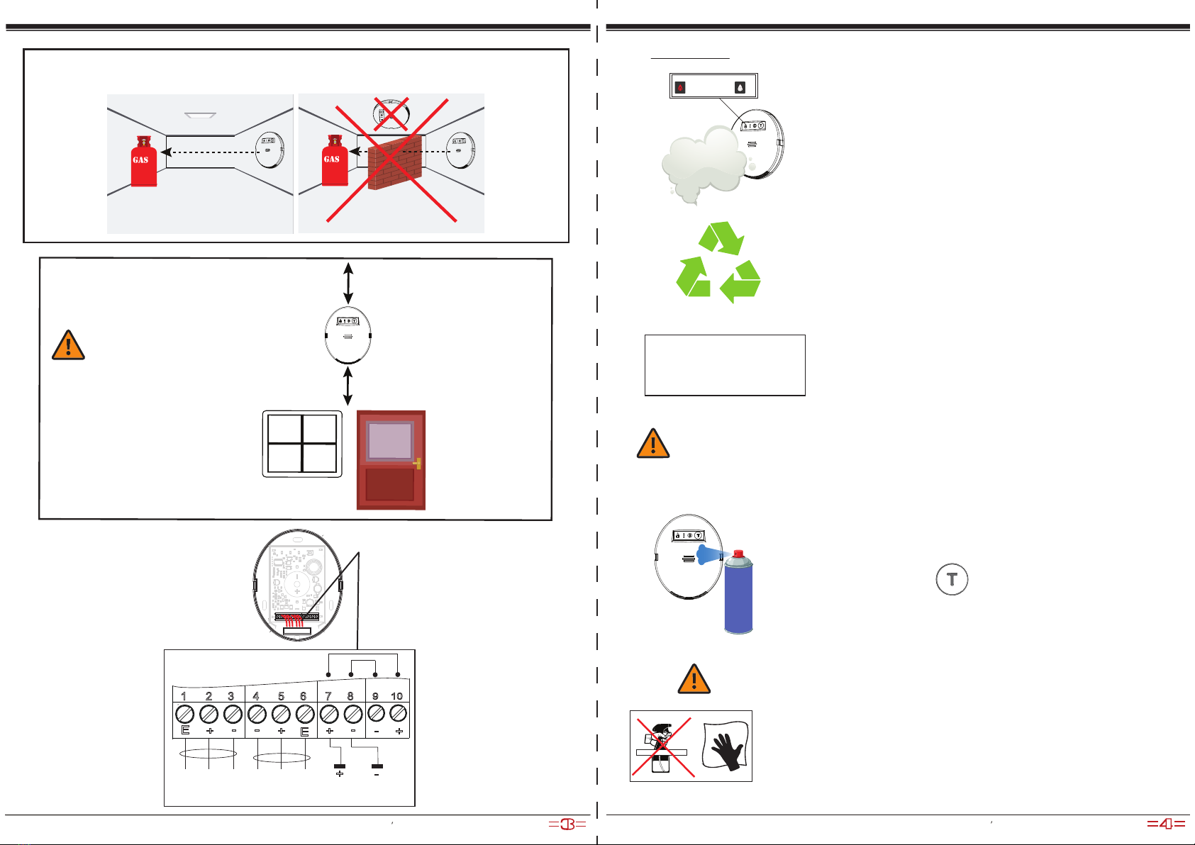
INSTALLATION
To mount the 71CNG detector,
please remove front panel.
The detector should be installed vertically at the wall – LEDs indicators are in the top-side
of the cabinet, the inlet openings are on the bottom side of the cabinet.
-5°С +40°С
The gas detector must not be mounted:
– Directly above cooking appliances;
– Directly above a sink;
– Adjacent to extractor fans;
– In any outside location;
– Where the environment conditions are outside
of operational specication.
Manufacturer: UniPOS Ltd., 47 San Stefano Street, Pleven 5800, Bulgaria, http://www.unipos-bg.com Manufacturer: UniPOS Ltd., 47 San Stefano Street, Pleven 5800, Bulgaria, http://www.unipos-bg.com