manuals.online logo
Brands
  1. Home
  2. •
  3. Brands
  4. •
  5. UniPOS
  6. •
  7. Smoke Alarm
  8. •
  9. UniPOS YKB-02? User manual

UniPOS YKB-02? User manual

UniPOS Duct Smoke Detector УКВ-02
Passport page 4
Revision 01.10 of 4
MAINTENANCE
The maintenance must be performed by an authorized person and includes
the service schedule of the device itself and the included in it fire detector and
remote indicator in accordance with their instruction manuals. Additional cleaning
the body of the duct detectoris is required.
CONDITIONS OF STORAGE, OPERATION AND TRANSPORT
1. Storage
oIndoor compartments
oStrorage Temperature Range - from minus 10 оСto plus 40 оС
oStorage Relative Humidity - up to 65 %
2. Operation
oEnclosed spaces where there are no aggressive fumes
oOperating Temperature Range - from minus 10 oC to plus 55 оC
oOperating Humidity Range - from 20% to 90% at 40 оC
3. Transportation
Product has to be transported in closed vehicles in factory packaging.
WARRANTY
The warranty period is 18 months from the date of sale providing .
The manufacturer guarantees the normal operation of the device providing that the
installation requirements from this Instructional manualhave been observed.
Manufacturing company bears no warranty liabilities for damages caused by
mechanical damage, improper use of the device or amendments and modifications
made after production. The manufacturer carries a warranty liability only for
damages caused by company's negligence or fault .
UniPOS
47, “San Stefano” Str., 5800 Pleven, BULGARIA
phone +359 64 891111, +359 64 891 100, fax +359 64 891 110
e-mail: office_pleven@unipos-bg.com
Mladost 1, bl.79B, entr.2, ap.17, 1784 Sofia, BULGARIA
phone/fax +359 2 9744469, +359 2 9743925
e-mail: office_sofia@unipos-bg.com
www.unipos-bg.com
UniPOS Duct Smoke Detector УКВ-02
Passport page 1
Revision 01.10 of 4
DUCT SMOKE DETECTOR
TYPE YKB-02К(YKB-02A)
Instruction Manual 01.10
GENERAL DESCRIPTION
Duct smoke detector YKB-02 is designed to detect the presence of smoke in
airstream of ductwork sections or ventilating compartments by the smoke detector
mounted in it.
Depending on the type of the fire detector mounted , the
duct smoke detector is produced in two variants -
for Conventional Fire Alarm Systems (YKB-02K) and for
Addressable Fire Alarm Systems (YKB-02A).
In the device is mounted an optical-smoke fire detector type:
-FD8030 for Conventional Systems
or
-FD7130 for Addressable Systems
In order to conrol the condition of the integrated fire
detector, on the housing of the duct smoke detector is
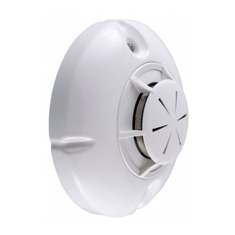
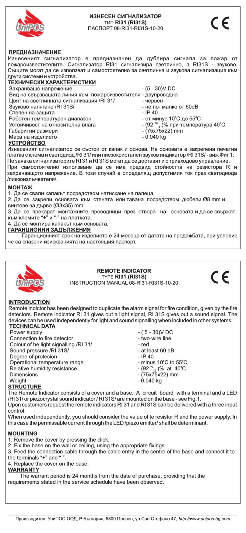
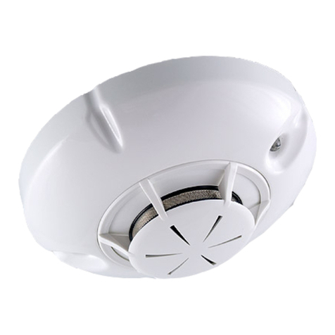
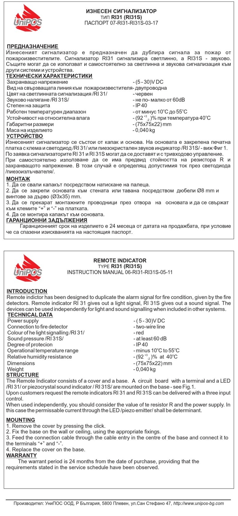
mounted an outboard LED Remote Indicator RI31.
Fig.1
Product design is based on the laws of Aerodynamics.
Part of the air flow runs through the opening holes ( pos.7, Fig 4 ) of the inlet tube
( pos.8, Fig.4 ) and passes through the duct smoke detector as reduces its speed
and goes out through the outlet tube ( pos.9, Fig 4 ).The mounted mechanichal
filters stop the large particles from the airflow and thus they protect the sensitive
element of the fire detector from dust contamination.
In case of smoke in the main air conduit, part of this smoke goes through the duct
smoke detector and activates the fire detector. The latter sends signal to the Fire
Control Panel and the outboard Remote indicator.
TECHNICAL DATA
Speed of the airflow into the air conduit - 0,5 ÷ 20 m/s
Existence of a mechanical filter of the input and the output - Yes
Base type of fire mounted detector - DB8000D (DB7100)
Type of the Fire Detector - FD8030 (FD7130)
Type of the mounted Remote Indicator - Rl31
Option for installation of different type smoke detectors - Yes
Dimensions (without the inlet tube , the outlet tube and the
nozzles)
(200x120x114)mm
Inlet tube dimensions ø22 х200 mm
Outlet tube dimensions ø22 х70 mm
Weight 1,3 kg
LABOUR PROTECTION REQUIREMENTS
The personnel authorized to conduct the mountage and the technical service should
be aware of the construction of the device its operational mode and the common
requirements of workplace security.
UniPOS Duct Smoke Detector УКВ-02 UniPOS Duct Smoke Detector УКВ-02
Passport page 2
Revision 01.10 of 4
Passport page 3
Revision 01.10 of 4
Any disassembly of the duct smoke detector from the main air conduit is
inadmissible except it is switched off.
4. Mount the device on the air conduit by the six self-tapping screws from the set,
and put the duct smoke detector in position so that the inlet tube holes (pos.7, Fig.
4) (poz.8, Fig.4) are upstream (poz.11, Fig.4) the air flow.Repairing is not allowed while the Fire Control Panel is plugged in the power
supply. 5. Unscrew the 8 screws (pos.1, Fig.4) and remove the lid (pos.2, Fig.4) of the
body (pos.5, Fig. 4) of the duct smoke detector.
INSTALLATION
1. On mechanical and electrical assemblage
of the device common iinstructions for fire
detector mountage in firealarm lines
(loops)should be followed.
2. There is possibility for the duct smoke
detector to be situated on the side, on top, or
below the air conduit only in case all the
instructions have been observed.
-inlet tube holes (pos.7, Fig.4) are facing the
80
186
135
22
Fig.2
Note: Removing the lid must be made with caution since the Remote indicator
(pos.3, Fig.4) is factory built-in together with the fire detector base.
Removing the lid provides access to the optical smoke fire detector.mounted in the
duct smoke detector.
6Take-off the fire detector (pos.4, Figure 4) from the base.
7. Lead the wires of the fire alarm line (loop) through the input and output
nozzles (pos.10, Fig.4) of the duct smoke detector.
8. Connect the wires to the base:
(Remote Indicator Rl31 (pos.3, Fig.4) is
factory built-in with the detestor base)
- for Conventional Control Panel (Fig.5).
air flow (pos.11, Fig 4 );
-visibility distance of the light-emitting
diode(LED) of the Remote Indicator
3. Drill mounting holes on a preliminary
specified project location of the air duct
according to the dimensions Figure 2.
On the inlet and outlet tubes place rubber
sealing washers from the set.
Air flow
Inlet tube
Outlet tube
Air conduit
+
Fig.5
Sealing
- for Addressable Control Panel (Fig.6)
Fig.3
1. Mounting Screw
2. Duct Detector Cover
3. Remote indicator
4. Optical-smoke fire detector
5. Duct Detector Housing
6. Holes for mountage on air conduit
7. Inlet tube holes
8. Inlet tube
9. Outlet tube
10. Nozzles
11. Airflow
1
2
3
4
5
6
7
8
9
10
+
Fig.6
9. Put the fire detector to its base.
10. Place the lid (position2, Figure 4) of the device and bolt up the screws (pos.1,
Figure 4).
COMPLEXITY
•Duct Smoke Detector with components assembled: - 1 pc
- Outboard Remote Indicators RI31;
- Detector Base DB8000D ( DB7100 );
- Optical-smoke fire detector FD 8030 ( FD7130 )
•Instruction Manual - 1 pc
11
•Self-tapping screws - 6 pcs
Fig.4 •Sealing - 1 pc
•Transport package - 1 pc

This manual suits for next models

1

Other UniPOS Smoke Alarm manuals

UniPOS RI31 User manual

UniPOS

UniPOS RI31 User manual

UniPOS FD 7130 User manual

UniPOS

UniPOS FD 7130 User manual

UniPOS FD 7130 User manual

UniPOS

UniPOS FD 7130 User manual

UniPOS FD 8030 User manual

UniPOS

UniPOS FD 8030 User manual

UniPOS RI31 User manual

UniPOS

UniPOS RI31 User manual

UniPOS EVPU FD 7130 User manual

UniPOS

UniPOS EVPU FD 7130 User manual

UniPOS 6130L User manual

UniPOS

UniPOS 6130L User manual

UniPOS FD8040 User manual

UniPOS

UniPOS FD8040 User manual

UniPOS FD 3030 User manual

UniPOS

UniPOS FD 3030 User manual

Popular Smoke Alarm manuals by other brands

bolid S2000-IPDL installation manual

bolid

bolid S2000-IPDL installation manual

Firex ADH owner's manual

Firex

Firex ADH owner's manual

Bentel Security FC400PH manual

Bentel Security

Bentel Security FC400PH manual

System Sensor INNOVAIR DH100ACDCLWP Installation and maintenance instructions

System Sensor

System Sensor INNOVAIR DH100ACDCLWP Installation and maintenance instructions

BRK electronic 650M owner's manual

BRK electronic

BRK electronic 650M owner's manual

ESYLUX PROTECTOR K 10 PLUS Installation and operating instructions

ESYLUX

ESYLUX PROTECTOR K 10 PLUS Installation and operating instructions

American Sensor SA308 manual 

American Sensor

American Sensor SA308 manual 

Red Smoke Alarms RFMDUAL user manual

Red Smoke Alarms

Red Smoke Alarms RFMDUAL user manual

innovair DH100ACDCI Installation and maintenance instructions

innovair

innovair DH100ACDCI Installation and maintenance instructions

Brooks EIB140e Series instruction manual

Brooks

Brooks EIB140e Series instruction manual

Kidde i12060 user guide

Kidde

Kidde i12060 user guide

Xtralis VESDA Commissioning Guide

Xtralis

Xtralis VESDA Commissioning Guide

Greenheck Combination Fire Smoke Dampers SSFSDR-511 Specifications

Greenheck

Greenheck Combination Fire Smoke Dampers SSFSDR-511 Specifications

Smoke hollow SH36GW Assembly & operation

Smoke hollow

Smoke hollow SH36GW Assembly & operation

BURGprotect Smoke 2050 user manual

BURGprotect

BURGprotect Smoke 2050 user manual

Kidde SMOKE AND CARBON MONOXIDE ALARM user guide

Kidde

Kidde SMOKE AND CARBON MONOXIDE ALARM user guide

Popp 004001 manual

Popp

Popp 004001 manual

Olympia BS-506/WL manual

Olympia

Olympia BS-506/WL manual

manuals.online logo
manuals.online logoBrands
  • About & Mission
  • Contact us
  • Privacy Policy
  • Terms and Conditions

Copyright 2025 Manuals.Online. All Rights Reserved.