Unipower ARR Series User manual

ARR Series Three Phase, Six Pulse SCR Charger Front Matter
RS-420, Rev. 7 i
RECEIVING INSTRUCTIONS
&
GENERAL EQUIPMENT INFORMATION
Please Note: For your protection, the following information and the product manual should be read and
thoroughly understood before unpacking, installing, or using the equipment.
UNIPOWER, LLC presents all equipment to the delivering carrier securely packed and in perfect
condition. Upon acceptance of the package from us, the delivering carrier assumed responsibility for its
safe arrival to you. Once you receive the equipment, it is your responsibility to document any damage the
carrier may have inflicted, and to file your claim promptly and accurately.
1. PACKAGE INSPECTION
1.1 Examine the shipping crate or carton for any visible damage: punctures, dents, and any other signs of
possible internal damage.
1.2 Describe any damage or shortage on the receiving documents, and have the carrier sign their full name.
1.3 If your receiving freight bill notes that a Tip-N-Tell is attached to your freight, locate it. If the Tip-N-Tell
arrow has turned even partially blue, this means the freight has been tipped in transport. Make sure the
carrier notes this on your receipt before you sign for the freight.
2. EQUIPMENT INSPECTION
2.1 Within fifteen days, open the crate and inspect the contents for damages. While unpacking, be careful not
to discard any equipment, parts, or manuals. If any damage is detected, call the delivering carrier to
determine appropriate action. They may require an inspection.
*SAVE ALL SHIPPING MATERIAL FOR THE INSPECTOR TO SEE!
2.2 After the inspection has been made, call UNIPOWER. We will determine if the equipment should be
returned to our plant for repair, or if some other method would be more expeditious. If it is determined
that the equipment should be returned to UNIPOWER, ask the delivering carrier to send the packages
back to UNIPOWER at the delivering carrier's expense.
2.3 If repair is necessary, we will invoice you for the repair so that you may submit the bill to the delivering
carrier with your claim form.
2.4 It is your responsibility to file a claim with the delivering carrier. Failure to properly file a claim for
shipping damages may void warranty service for any physical damages later reported for repair.
3. HANDLING
Equipment can be universally heavy or top-heavy. Use adequate humanpower or equipment for handling.
Until the equipment is securely mounted, be careful to prevent the equipment from being accidentally
tipped over.

ARR Series Three Phase, Six Pulse SCR Charger Front Matter
RS-420, Rev. 7 ii
4. NAMEPLATE
Each piece of UNIPOWER equipment is identified by a part number on the nameplate. Please refer to
this number in all correspondence with UNIPOWER.
5. INITIAL SETTINGS
All equipment is shipped from our production area fully checked and adjusted. Do not make any
adjustments until you have referred to the technical reference or product manual.
6. SPARE PARTS
To minimize downtime during installation or operation, we suggest you purchase spare fuses, circuit
boards and other recommended components as listed on the Recommended Spare Parts List in the back of
the product manual. If nothing else, we strongly recommend stocking spare fuses for all systems.
PRODUCT SUPPORT
Product support can be obtained using the following addresses and telephone numbers.
Corporate office:
UNIPOWER, LLC
210 N University Dr
Coral Springs, FL 33071
United States
Manufacturing facility:
UNIPOWER, LLC
65 Industrial Park Rd
Dunlap, TN 37327
United States
Manufacturing facility:
UNIPOWER Slovakia SRO
ZLATOVSKA 1279
Business Center 22
91105 Trencin, Slovakia
Phone: +1-954-346-2442
Toll Free: 1-800-440-3504
Web site – www.unipowerco.com
When contacting UNIPOWER, please be prepared to provide:
1. The product model number, spec number, S build number, and serial number - see the equipment nameplate
on the front panel
2. Your company’s name and address
3. Your name and title
4. The reason for the contact
5. If there is a problem with product operation:
•Is the problem intermittent or continuous?
•What revision is the firmware?
•What actions were being performed prior to the appearance of the problem?
•What actions have been taken since the problem occurred?

ARR Series Three Phase, Six Pulse SCR Charger Front Matter
RS-420, Rev. 7 iii
REVISION HISTORY
REV DESCRIPTION
CHECKED/APPROVED
& DATE
7 See PCO 45405 CJM / 8-8-19
PROPRIETARY AND CONFIDENTIAL
The information contained in this product manual is the sole property of UNIPOWER, LLC. Reproduction of the
manual or any portion of the manual without the written permission of UNIPOWER, LLC is prohibited.
© Copyright UNIPOWER, LLC
DISCLAIMER
Data, descriptions, and specifications presented herein are subject to revision by UNIPOWER, LLC without
notice. While such information is believed to be accurate as indicated herein, UNIPOWER, LLC makes no
warranty and hereby disclaims all warranties, express or implied, with regard to the accuracy or completeness of
such information. Further, because the product(s) featured herein may be used under conditions beyond its
control, UNIPOWER, LLC hereby disclaims and excludes all warranties, express, implied, or statutory, including
any warranty of merchantability, any warranty of fitness for a particular purpose, and any implied warranties
otherwise arising from course of dealing or usage of trade. The user is solely responsible for determining the
suitability of the product(s) featured herein for user’s intended purpose and in user’s specific application.
Throughout the remainder of this manual, “UNIPOWER” will mean “UNIPOWER, LLC.”
PERSONNEL REQUIREMENTS
Installation, setup, operation, and servicing of this equipment should be performed by qualified persons
thoroughly familiar with this Product Manual and Applicable Local and National Codes. A copy of this manual is
included with the equipment shipment.

ARR Series Three Phase, Six Pulse SCR Charger Front Matter
RS-420, Rev. 7 iv
TABLE OF CONTENTS
1. INTRODUCTION..................................................................................................................................... 1-1
1.1 PURPOSE AND USE ................................................................................................................................. 1-1
1.2 IDENTIFICATION ..................................................................................................................................... 1-2
2. INSTALLATION....................................................................................................................................... 2-1
2.1 UNPACKING.............................................................................................................................................. 2-1
2.2 LOCATION................................................................................................................................................. 2-1
2.3 MOUNTING ............................................................................................................................................... 2-1
2.4 POWER SOURCE ...................................................................................................................................... 2-1
2.5 CONNECTIONS (REFER TO DRAWINGS IN BACK OF MANUAL) .................................................. 2-1
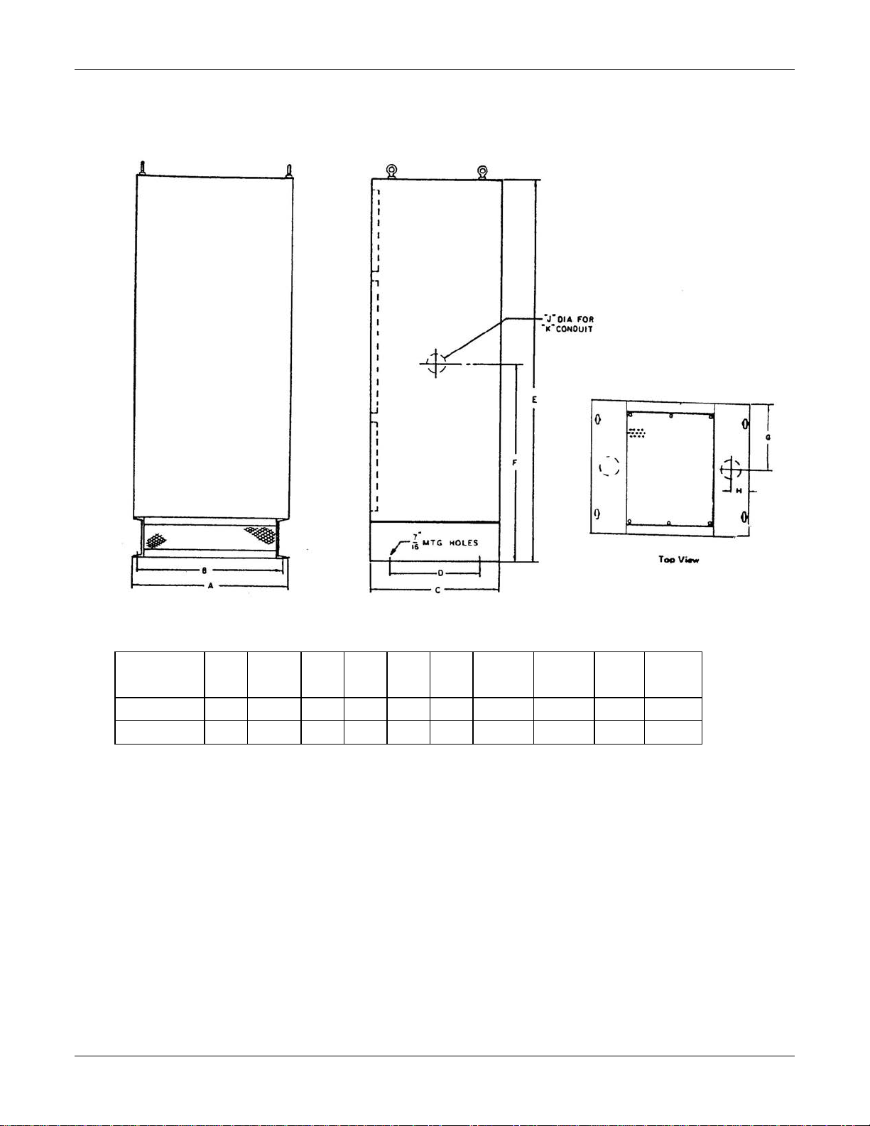
2.5.1 Cabinet Dimensions................................................................................................................................. 2-3
2.5.2 Preliminary Adjustments.......................................................................................................................... 2-5
2.5.3 Float Voltage Adjustment........................................................................................................................ 2-5
2.5.4 Equalize Voltage Adjustment.................................................................................................................. 2-6
2.5.5 Current Limit Adjustment........................................................................................................................ 2-6
2.5.6 High Voltage Shutdown........................................................................................................................... 2-7
3. OPERATION............................................................................................................................................. 3-1
3.1 STARTING AND STOPPING.................................................................................................................... 3-1
3.2 METERS ..................................................................................................................................................... 3-1
3.3 FLOAT-EQUALIZE OPERATION............................................................................................................ 3-1
3.4 DESCRIPTION OF OPERATION.............................................................................................................. 3-1
3.4.1 Block Diagram......................................................................................................................................... 3-1
4. ROUTINE MAINTENANCE................................................................................................................... 4-1
5. CORRECTIVE MAINTENANCE........................................................................................................... 5-1
5.1 VOLTAGE CHECKPOINTS...................................................................................................................... 5-1
5.2 BALANCING PROCEDURE..................................................................................................................... 5-1
5.2.1 2010 Series (Refer to Cabinet Dimension section).................................................................................. 5-1
5.2.2 1329 Series (Refer to Cabinet Dimension section).................................................................................. 5-1
5.3 VOLTAGE CHECKPOINT SCHEMATIC (GENERALIZED)................................................................. 5-2
5.4 SPECIFIC PROBLEM CHART.................................................................................................................. 5-3
5.5 INSTRUCTION NOTES............................................................................................................................. 5-5
5.5.1 Checking of Potentiometers..................................................................................................................... 5-5
5.5.2 Checking of Diodes and Silicon Controlled Rectifiers............................................................................ 5-5
5.5.3 Checking the Current Transformer.......................................................................................................... 5-8
5.5.4 Checking the Auxiliary Transformer....................................................................................................... 5-8
5.5.5 Checking DC Filter Capacitors................................................................................................................ 5-8
5.5.6 Checking of Printed Circuit Control Cards.............................................................................................. 5-9
6. CIRCUIT DESCRIPTIONS..................................................................................................................... 6-1
6.1 BASIC CONTROL...................................................................................................................................... 6-1
6.2 CONTROL BOARD SCHEMATICS......................................................................................................... 6-3
6.3 CONTROL BOARD PARTS LIST............................................................................................................. 6-4
6.4 CONTROL BOARD "A" (MBC01970-1) .................................................................................................. 6-6
6.5 CONTROL BOARD “B” (MBC01971-2) .................................................................................................. 6-6
6.6 INTER-PHASE BALANCE BOARD......................................................................................................... 6-7
7. ACCESSORIES AND OPTIONAL EQUIPMENT ............................................................................... 7-1

ARR Series Three Phase, Six Pulse SCR Charger Introduction
RS-420, Rev. 7 1-1
1. INTRODUCTION
1.1 PURPOSE AND USE
The purpose of the UNIPOWER AutoReg®battery charger is the conversion of AC power to DC power for the
proper maintenance of a battery in the fully charged condition.
The battery is maintained in the fully charged state, because the AutoReg®will continually deliver a DC output
equal to the given load, provided that load does not exceed the DC output rating indicated on the nameplate.
The battery then is said to be in float service. Since, unless there is an AC power failure, the battery will not be
required to provide the power needed for the load, it remains fully charged.
In the AutoReg®charger, when the AC line supply is within the limits of 10% above or below the AC voltage
rating on the nameplate, and 5% above or below the AC frequency rating on the nameplate, the charger will
maintain a steady DC output voltage within ±½%, for any load from 0% to 100%. The efficiency of the charger
is shown by the following graph.
On the AutoReg®charger, the float and equalize voltages can be adjusted within the range of 10% above or below
the nominal voltages, which are factory set.
The AutoReg®charger has incorporated into its control circuitry a current-limit system. This is factory set at
115% of the rated output. The following graph shows the effectiveness of the current-limit.

ARR Series Three Phase, Six Pulse SCR Charger Introduction
RS-420, Rev. 7 1-2
The internal arrangement of the typical model of the AutoReg®charger is given on the drawings in the back of
this manual. This is shown to aid in the location of the more common adjustment points and terminal points in
the charger.
1.2 IDENTIFICATION
All UNIPOWER AutoReg®chargers are equipped with a full identification nameplate, as shown in the example
below.
NOTE: When requesting information, or ordering spare parts, please specify the Model No. and Serial No. of the
charger. This information will speed your request.
AC VOLTS 480 PH 3
HZ 60
AC AMPS 27
DC VOLTS 132 CELLS 60
DC AMPS 100
MODEL NO. ARR130K100 SPEC. S04545
SER.NO. FPS06 16558 °T C 50

ARR Series Three Phase, Six Pulse SCR Charger Installation
RS-420, Rev. 7 2-1
2. INSTALLATION
2.1 UNPACKING
Unpack carefully to avoid marring the case or damaging the equipment. Make sure that no small parts are mislaid
or thrown away with the packing material. If you are not going to use the equipment immediately, store it in a dry
place and protect it from accidental damage.
2.2 LOCATION
The equipment should be installed in a convenient, dry place, protected from overhead drip. Adequate ventilation
is required for proper functioning. It is recommended that 3 to 6 inches of free air space be provided on each side
of the charger.
The equipment can be operated in elevated temperatures for some time without harm. However, if the
charger is to be in continuous operation in temperatures above 50°C (122°F), it is recommended that the charger
be located in an air conditioned room. In temperatures below -20°C (-4°F), heaters should be installed.
The charger, like all electrical equipment, should not be mounted where it would be subjected to extreme
vibration which could possibly cause a malfunction.
2.3 MOUNTING
Chargers are floor mounted. The dimensions of the different cabinet series are shown on page 4. If in doubt as to
which cabinet series your charger belongs, refer to the chart on page 4, for the cabinet series number of your
model.
2.4 POWER SOURCE
To function properly, the AC supply voltage (i.e. the AC input line) must be within the limits of ±10% of the
voltage rating stamped on the nameplate; and ±5% of the frequency rating (frequency is indicated by Hertz on
nameplate).
The chart on page 4 list the possible AC supply voltages and current draws for all standard models of the ARR
AutoReg®charger. The cabinet series is also indicated on this chart, as well as the DC voltage range.
If the source voltage is other than the rated value, or if the sustained AC voltage fluctuations are beyond the range
of ±10%, contact the nearest sales office of UNIPOWER.
2.5 CONNECTIONS (REFER TO DRAWINGS IN BACK OF MANUAL)
The charger input and output connection points are reached through the hinged front or removable top panel.
The AC input connections are made to the AC terminal points on the terminal board. The DC output connections
are located opposite the AC connection points on the terminal board. Both the AC and DC connection points are
clearly marked on the board.

ARR Series Three Phase, Six Pulse SCR Charger Installation
RS-420, Rev. 7 2-2
Follow carefully this procedure for making AC and DC connections to the charger:
1. Place the AC circuit breaker in the “OFF” position.
2. The battery should remain disconnected and the DC circuit breaker placed in the “OFF” position.
3. Place the “NORMAL-EQUALIZE” toggle switch in the “NORMAL” position.
4. Check the card (pictured above) supplied with the charger to see if the transformer primary terminal
block is connected in the proper sequence for your incoming AC line voltage.
If you have a different line voltage, and the transformer primary is not connected in the proper
sequence, refer to the INSTALLER’S DIAGRAM. Then, reconnect the transformer primary terminal
block as indicated. NOTE: If your charger is not equipped with an AC fuse, the AC circuit breaker
must be changed to meet the proper current and voltage ratings whenever the AC input is reconnected.
5. Connect the incoming AC leads to the AC terminal blocks located on the terminal board. (Be sure that
the AC input leads are connected to points marked L1, L2, and L3.)
6. Connect the DC positive and the negative leads from the battery to the designated terminal points on the
terminal board. Make sure all connections are tight, and that the correct polarity has been observed (i.e.
Positive to Positive and Negative to Negative).
7. CLOSE THE DC CIRCUIT BREAKER. This energizes the charger filter capacitors connected across
the DC output. The DC voltmeter on the front panel should read the battery voltage and ammeter
should read zero or slightly above.
8. Close the AC circuit breaker. The DC ammeter on the front panel will register the current flow and the
charger voltage will gradually increase as your battery charges to the floating voltage level which was
set at the factory.
9. (Acceptable alternate sequence) Close the ac circuit breaker. The charger output voltage slowly rises to
the float voltage set point. The filter capacitors will be charged by the charger.
10. Close the dc breaker. The dc ammeter will register the current flow to the load and battery.
It is possible to damage the rectifier stack or blow the anode fuses if the above procedures are not followed.

ARR Series Three Phase, Six Pulse SCR Charger Installation
RS-420, Rev. 7 2-3
2.5.1 Cabinet Dimensions
CABINET
SERIES
A
B
C
D
E
F
G
H
J
K
1329
28”
26.5”
20”
14”
58”
41”
9.875”
2.625”
3”
2.5”
2010
36”
34.5”
17”
17”
78”
15”
4”

ARR Series Three Phase, Six Pulse SCR Charger Installation
RS-420, Rev. 7 2-4
CABINET
AC
INPUT
DC OUTPUT
Model
Series
Shpg. Wt.
Current
Voltage
Cells
Current
(lbs.)
(amps)
NOM4
Adj.
Range
(amps.)
ARR130HK50
1329
450
28/14
132
120-145
56-64
50
ARR130HK75
1329
550
42/21
132
120-145
56-64
75
ARR130HK100
1329
650
54/27
132
120-145
56-64
100
ARR130HK150
1329
800
82/41
132
120-145
56-64
150
ARR130H200
2010
1100
108
132
120-145
56-64
200
ARR130K200
2010
1100
54
132
120-145
56-64
200
ARR260HK25
1329
450
28/14
264
240-290
112-
128
25
ARR260HK50
1329
650
54/27
264
240-290
112-
128
50
ARR260HK75
1329
800
82/41
264
240-290
112-
128
75
ARR260H100
2010
1100
108
264
240-290
112-
128
100
ARR260K100
2010
1100
54
264
240-290
112-
128
100
1 -- AC input voltage -- 240/480 volts at 60 Hz.
2 -- AC input voltage -- 240 volts at 60 Hz.
3 -- AC input voltage -- 480 volts at 60 Hz.
4 -- Guaranteed output voltage regulation range.

ARR Series Three Phase, Six Pulse SCR Charger Installation
RS-420, Rev. 7 2-5
2.5.2 Preliminary Adjustments
All adjustments are factory set. The settings are indicated by the red card (pictured here) attached on the inside
front of the charger.
However, you may wish to change some of the following settings to fit your particular battery. (This chart,
shown below, shows the proper float and equalize voltages for the different battery types.
Proper Float & Equalize Voltages
Cell Voltages
Type
Float
Equalize
Lead Antimony
2.15
2.33
Lead Calcium
2.17-2.20
2.33
Not required
Nickel-Cadmium
1.43
1.55
Nickel-Iron
1.50-1.55
1.60-1.65
2.5.3 Float Voltage Adjustment
The float potentiometer controls the floating voltage of the charger when the toggle switch is in the “NORMAL”
or “FLOAT” positions.
NOTE: Both “FLOAT” and “EQUALIZE” Potentiometers are 10-turn devices.
The adjustment control (potentiometer) for float voltage is located on the front of your charger, marked FL. By
turning the potentiometer clockwise, you increase the float voltage. If you turn the potentiometer
counterclockwise, you decrease the float voltage.
In order to correctly adjust the float voltage the battery should be in a fully charged condition with some load
connected. While the unit is in operation, adjust the float potentiometer to float voltage desired.
(The voltage reading is indicated on the charger’s voltmeter.)
The float voltage will depend upon the type of battery, and the type of service for which the battery is used (e.g.
communications).

ARR Series Three Phase, Six Pulse SCR Charger Installation
RS-420, Rev. 7 2-6
NOTE: Keep the toggle switch in the “FLOAT” position during regular operation.
2.5.4 Equalize Voltage Adjustment
The potentiometer for this adjustment is also on the front of the charger marked EQ.
Move the toggle switch to the “EQUALIZE” position. Then, with the charger in operation, as it was during float
voltage adjustment, make your equalize voltage adjustment.
The equalize voltage potentiometer works exactly at the float voltage potentiometer - a clockwise turn increases
voltage; a counterclockwise turn decreases voltage.
The equalize voltage setting will depend upon the type of battery used (refer to chart), and the maximum limiting
voltage of the connected load equipment.
NOTE: Always return the toggle switch to “FLOAT” position at the end of the equalizing charge.
2.5.5 Current Limit Adjustment
The current limit is factory set at 115% of the rated output of the charger.
If a higher current limit setting is desired, the potentiometer may be set within the range of 100% to 125% of the
rated output. However, this maximum percentage (125%) should not be maintained continuously. The charger
can only be guaranteed for two hours at a 50°C ambient temperature, when operating at 125% of the rated output.
If the current limit setting of 125% is exceeded, or the charger is operated at this output longer than two hours, the
charger warranty will become null and void.
Any adjustments above 125% of the rated output should be made by a UNIPOWER service personnel. If the
current limit setting is changed without authorization by UNIPOWER warranty will become null and void.
The current limit potentiometer, which is located on the 9 point control board, is adjusted in the following
manner:
1. Remove AC power from the charger by opening the AC circuit breaker.
2. Allow battery voltage to drop a few volts. This will discharge the battery enough to require the charger
to operate in the current limit range, when it is turned on. If there is a dummy load available, adjust
until 115% of the charger rating is reached.
3. Close the AC circuit breaker allowing AC power to the charger. The charger will now be operating in
the current limit range of 115% of the rated output (factory set).
4. Now, slowly adjust the potentiometer shaft counterclockwise (some pressure may be needed when first
turning the shaft until the factory seal is broken), until the current reaches 125%, or the desired current
below 125% of the charger’s rated output. For example, on a 10 amp charger, stop when the current
reaches 12.5 amps.
5. Check setting by repeating steps 1, 2, and 3.
CAUTION: Do not attempt to set float or equalize voltages until the charger drops out of the current limit range,
or until the charger output returns to normal.

ARR Series Three Phase, Six Pulse SCR Charger Installation
RS-420, Rev. 7 2-7
2.5.6 High Voltage Shutdown
The high voltage shutdown is designed to operate up if the charger output goes to high voltage. There are two
different high voltage shutdown system. One system uses a latching relay and the other system uses a shunt trip
curcuit breaker on the input of the charger. To determine which system is installed in the charger either consult
the charger schematic and wiring diagram or check the charger for the hardware described for the each of the
shutdown systems.
LATCHED RELAY SYSTEM: When a high voltage is sensed, the latching relay system’s high voltage
shutdown board disconnects the auxiliary voltage transformers. Disconnecting the auxiliary voltage transformers
results in no control power for the charger causing the charger to shut off.
The high voltage shutdown is a latching device that must be manually reset when the unit is activated. A reset
button is located on the face of the high voltage shutdown unit. When reset the charger will restart. If the unit
shutsdown again, check for the cause of the high voltage condition.
Unless otherwise requested, the high voltage shutdown is factory set to 148 volts dc for a 130 volt charger or 295
volts dc for a 260 volt charger. It is recommended the that the shutdown setting be kept at least 15% above the
equalize voltage setting.
In order to check that your high voltage shutdown is properly set, follow this procedure:
1. Disconnect the battery if possible and apply a small load, approximately 1 amp, to the charger.
2. Connect an ohmmeter on terminals 7 and 8, the C-NO (common-normally open) contacts; and jumper
terminals 3 and 4.
3. Place the charger in equalize.
4. Use the equalize adjustment to slowly raise the charger output voltage until the ohmmeter reads no
resistance. This would mean that under normal operation as a battery charger, the high voltage
shutdown would have been activitated and the charger would have consequently shutdown.
5. If the high voltage shutdown is properly set per the factory levels, the ohmmeter should show no
resistance at 152 volts dc for a 130 volt charger or 305 volts dc for a 260 volt charger.
However, if these readings are not obtained, or a higher setting is desired, follow this procedure:
NOTE: Be sure to reset the high voltage shutdown before beginning these steps.
1. Repeat steps 1, 2, and 3 of the check procedure.
2. Turn the Voltage Adjustment Potentiometer of the high voltage shutdown completely clockwise.
3. Adjust the equalize voltage until the desired “trip” voltage is obtained.
4. Then slowly turn the Voltage Adjustment Potentiometer of the high voltage shutdown counter-
clockwise until the ohmmeter reads no resistance.
5. Turn the equalize voltage down, reset the relay, and repeat step 3 as a check for the correct shutdown
setting.
6. On high voltage shutdown units with variable time delay, turn the delay time adjusting potentiometer
full counter-clockwise until the voltage trip point is adjusted. Then return the delay time to the desired
setting and recheck settings.
SHUNT TRIP SYSTEM: With the shunt trip system the high voltage condition causes the shutdown board to
energize a relay on the board. The relay operates energizing the shunt trip coil on the ac circuit breaker causing
the breaker to trip and shut off the charger. The high voltage shutdown circuit board for the shunt trip system
may be silk-screened “High Voltage Alarm.“

ARR Series Three Phase, Six Pulse SCR Charger Installation
RS-420, Rev. 7 2-8
Once activated the high voltage shutdown is reset by moving the ac circuit breaker operator from the “tripped”
position to the “off” position and then to the “on” position. This will restart the charger. If the breaker trips
again, check for the cause of the high voltage condition.
Unless otherwise requested, the high voltage shutdown is factory set to 148 volts dc for a 130 volt charger or 295
volts dc for a 260 volt charger. It is recommended the that the shutdown setting be kept at least 15% above the
equalize voltage setting.
In order to check that the high voltage shutdown is properly set, follow this procedure:
1. Disconnect the battery if possible and apply a small load, approximately 1 amp, to the charger.
2. Place the charger in equalize and use the equalize adjustment to slowly raise the charger output voltage
to the setpoint.
3. The ac breaker will trip when the setpoint is reached.
4. If the high voltage shutdown is properly set per the factory levels, the ac circuit breaker will trip at 152
volts dc for a 130 volt charger or 305 volts dc for a 260 volt charger.
Note: The setpoint can be checked without tripping the ac breaker by disconnecting one of the connections to the
shunt trip coil and listening for the relay to energize or measuring voltage at the relay contact(s).
However, if these readings are not obtained, or a higher setting is desired, follow this procedure:
NOTE: Be sure to reset the charger before beginning these steps.
1. Repeat steps 1 and 2 of the check procedure.
2. Turn the voltage setpoint adjustment of the high voltage shutdown (alarm ) board completely
clockwise.
3. Adjust the equalize voltage until the desired “trip” voltage is obtained.
4. Then slowly turn the voltage setpoint adjustment counter-clockwise until the ac circuit breaker (or
relay) operates.
5. Turn the equalize voltage down, reset the ac circuit breaker, if necessary, and repeat step 3 as a check
for the correct shutdown setting.
6. Reconnect the shunt trip if necessary and re-set the equalize voltage when setting the high voltage
shutdown is completed.

ARR Series Three Phase, Six Pulse SCR Charger Operation
RS-420, Rev. 7 3-1
3. OPERATION
3.1 STARTING AND STOPPING
After the charger has been installed and the connections made, to activate the unit, simply close the DC circuit
breaker (move DC switch to “ON” position).
CAUTION: It is recommended to always close the DC breaker before the AC breaker so that the filter cans (if
the unit is filtered) are charged from the battery.
It is possible to damage the rectifier stack or blow the anode fuses if above procedure is not followed.
3.2 METERS
The DC output voltage is indicated by a voltmeter on the front panel of the charger. The DC output current is
shown by an ammeter on the front panel.
3.3 FLOAT-EQUALIZE OPERATION
The float-equalize switch on the front panel of the charger should remain in the “NORMAL” or “FLOAT”
position for regular or float operation.
When higher than a normal charge is desired on a discharged battery, a higher DC voltage may be obtained by
putting the toggle switch in the “EQUALIZE” position. Refer to the chart on page 5 for the proper float and
equalize voltages for specific battery types.
3.4 DESCRIPTION OF OPERATION
A three-phase AC input voltage is supplied to three delta connected power transformers, one phase to each
transformer. The transformers change the voltage level of the AC input and the transformer secondaries feed
three rectifier units. The rectifier unit is a full wave bridge consisting of two SCR’s and two silicon diodes. The
SCR’s are used for control of the DC output as well as for rectification. Control is accomplished by controlling
the conduction time of the SCR’s. This will be discussed more fully later. The outputs of the rectifiers are tied
together in parallel so that current is additive. The rectified output is then fed through an optional output filter to
the DC output of the charger.
3.4.1 Block Diagram
The Control Circuits consist of three parts: a voltage sensing circuit, a current sensing circuit, and a phase
controlling circuit.

ARR Series Three Phase, Six Pulse SCR Charger Operation
RS-420, Rev. 7 3-2
The phase controlling circuit consists of three printed circuit boards (control boards B). Each board controls a
pair of SCR’s in a rectifier unit. The purpose of these boards is to form pulses that will turn on the SCR’s at the
proper time. The earlier in the cycle the SCR’s are turned on, the more output is produced.
The voltage sensing circuit (control board A) compares the output voltage with a reference voltage produced
within the circuit. When error develops between the output voltage and the reference voltage, an error signal is
fed to the phase controlling boards causing them to fire the SCR’s at the proper time to maintain the output
voltage.
The current sensing circuit (also on control board A) receives a signal from the current transformers. When the
output current increases beyond the current limit setting the signal from the current sensing circuit overrides the
voltage sensing circuit and feeds a signal to the phase control boards which fires the SCR’s at the time necessary
to limit the output current to the set level.
There is another board (control board C) that is part of the control circuits. This board is connected between the B
boards and the A board; and also between the current transformer and the A board. Its purpose is to tie the signal
from the A board to the B boards, to tie the signal from current transformers to the A board, and to set the outputs
from all the rectifier units at equal levels.
Power is provided to the Control Circuits by three auxiliary transformers. The primaries of these transformers are
connected to auxiliary windings on the power transformers. The secondary voltages of the auxiliary voltage
transformers are in phase with the power transformer voltages that supply the rectifier units. These voltages
supply the phase control boards which in turn control the rectifier units having supply voltages with the same
phase. The A board is supplied from its interconnections with the B boards.
An AC circuit breaker is provided on the input to the charger. The breaker provides overload and short circuit
protection for the charger and serves as the disconnect means for AC power. There are anode fuses on the
rectifier units to protect the rectifier against fault currents. A snubber, consisting of a capacitor and resistor in
series, is connected each across the rectifier unit preventing high voltage spikes from appearing across the rectifier
unit. A DC circuit breaker is provided on the output of the charger to protect against external faults and to allow
connection of the battery to the charger without causing arcing due to the capacitors charging.

ARR Series Three Phase, Six Pulse SCR Charger Routine Maintenance
RS-420, Rev. 7 4-1
4. ROUTINE MAINTENANCE
CAUTION: The charger will have live terminals unless both the AC power source and the battery are
disconnected. Be careful, to avoid electric shocks and burns.
a. Ventilation is of prime importance. Check the area around the charger; be sure that nothing interferes
with the free flow of air.
b. Check for dust deposits. Dust on the heat radiating surfaces and contacts of the charger will greatly
reduce heat dissipation. Dust and other accumulations should be removed regularly.
c. The area around the charger should be kept dry. On occasion, condensation may form, especially when
the unit is idle; this should be cleaned to prevent fungus growth.
d. Connections at the terminals should be clean, and should be tight. Heating of terminals is a definite
indication of corroded or loose terminal connections. Fuse clips particularly are subject to overheating
and corroding. They should be checked regularly for proper tension and cleanliness of contact area.
e. Float and equalize voltage should be checked occasionally and readjusted if necessary. (Refer to Float
and Equalize Voltage Adjustment on pages 5 & 6.)
f. When possible, the current limit operation should be checked. If current limit occurs when the load
current is too high, overloads may damage the unit. (Refer to Current Limit Adjustment on page 6, if
necessary.)
g. To insure accurate voltage readings, periodically check the floating voltage as shown on the charger’s
panel voltmeter, using a portable standard voltmeter. If necessary, adjust the panel voltmeter to agree
with the standard voltmeter by using the zero adjustment, located on the face of the charger’s panel
voltmeter.

ARR Series Three Phase, Six Pulse SCR Charger Corrective Maintenance
RS-420, Rev. 7 5-1
5. CORRECTIVE MAINTENANCE
5.1 VOLTAGE CHECKPOINTS
When there is no DC output on the charger, check the following list for possible failure points in the charger.
(The schematic given on page 10 indicates points where a voltage reading should be taken. The chart on the
schematic lists the proper voltages to be found at each point.)
5.2 BALANCING PROCEDURE
5.2.1 2010 Series (Refer to Cabinet Dimension section)
1. Remove two 18 point B control boards. Energize the charger according to instructions in the manual
and load the charger to 1/3 of rated output.
2. Connect the probe of the oscilloscope to the AC inputs of the active SCR bridge. The voltage
waveform should look like Fig. 1. If the horizontal spacings in the waveform are unequal, adjust the
reactor balance pot located on the 18 point “B” control board for that phase so that the pattern is
symmetrical. Repeat this step for the remaining SCR bridges, operating unit on one phase only for each
balancing process. Mark each board with the phase it was tested in.
3. Replace all boards in their respective phases. Connect the probe of the scope to the DC output
terminals and examine the ripple pattern. The waveform should look like Fig. 2. To balance the
pattern, readjust the reactor balance pots in Step 1.
5.2.2 1329 Series (Refer to Cabinet Dimension section)
1. Repeat Steps 1 & 2 of the above procedure.
2. Replace all boards in their respective phases. Connect an amprobe (clip-on ammeter) to one of the AC
input leads to an SCR bridge and note the current. Repeat this for the remaining SCR bridges. The
readings should be close.
3. If a phase is out of balance, adjust the phase balance pot for that phase, which is located on the control
panel, until the current is about equal to the other phases. Recheck the current balance in the other two
phases. There should be no more than a 5 amp difference between phases.

ARR Series Three Phase, Six Pulse SCR Charger Corrective Maintenance
RS-420, Rev. 7 5-2
5.3 VOLTAGE CHECKPOINT SCHEMATIC (GENERALIZED)
This manual suits for next models
12
Table of contents
Other Unipower Batteries Charger manuals