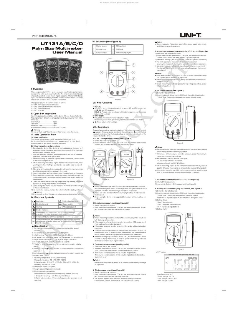
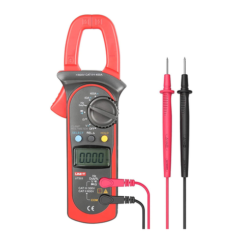
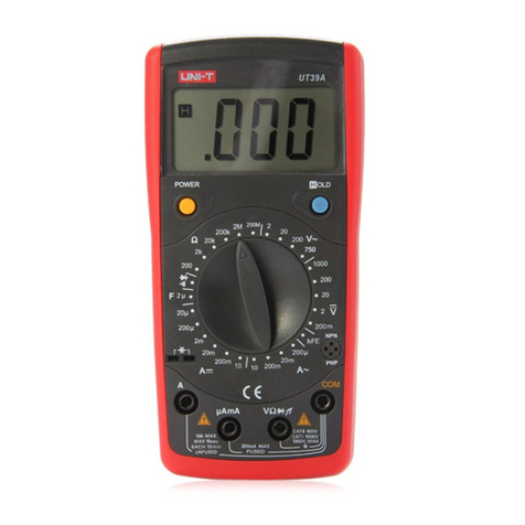
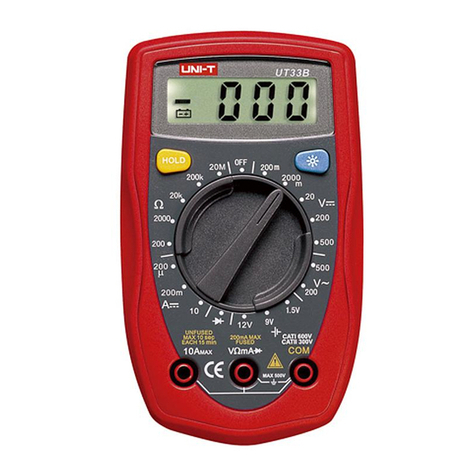
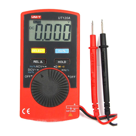
Unit UT15B PRO User manual

Preface
Thank you for purchasing this brand new multi-meter. In order to use this product safely and correctly, please
read this manual thoroughly, especially the Safety Instructions part.
After reading this manual, it is recommended to keep the manual at an easily accessible place, preferably close
to the meter, for future reference.
Limited Warranty and Liability
Uni-Trend guarantees that the product is free from any defect in material and workmanship within one year
from the purchase date. This warranty does not apply to damages caused by accident, negligence, misuse,
modification, contamination or improper handling. The dealer shall not be entitled to give any other warranty on
behalf of Uni-Trend. If you need warranty service within the warranty period, please contact your seller directly.
Uni-Trend will not be responsible for any special, indirect, incidental or subsequent damage or loss caused by
using this meter.

4
3
1. Overview ---------------------------------------------------------- 4
2. Standard Accessories ------------------------------------------ 4
3. Safety Instruction ----------------------------------------------- 5
3.1 Safety Certifications --------------------------------------- 5
3.2 Safety Instruction -------------------------------------------5
4. Electric Symbols ------------------------------------------------- 7
5. Comprehensive Specification -------------------------------- 8
6. External Structure ----------------------------------------------- 9
7. LCD Display ----------------------------------------------------- 10
8. Function Selection Knob and Buttons --------------------- 11
9. Measurement Operation Instruction ----------------------- 13
9.1 AC Voltage Measurement ------------------------------ 13
9.2 DC Voltage Measurement ------------------------------ 14
9.3 Resistance and Circuit Continuity Measurement -- 15
9.4 Diode Measurement -------------------------------------- 16
9.5 Capacitance Measurement ---------------------------- 17
9.6 AC/DC Current Measurement ------------------------- 18
9.7 Frequency and Duty Ratio Measurement
(Only UT17B PRO)------------------------------------------18
9.8 Temperature Measurement (Only UT17B PRO)-----19
9.9 Others ----------------------------------------------------------19
10. Specification -------------------------------------- 20
10.1 DC Voltage Measurement --------------- 20
10.2 AC Voltage Measurement --------------- 21
10.3 Resistance Measurement --------------- 22
10.4 Continuity Test And Diode
Measurement-------------------------------- 22
10.5 Capacitance Measurement -------------- 23
10.6 Frequency/Duty ratio Measurement
(Only UT17B PRO) ------------------------ 24
10.7 Temperature Measurement
(Only UT17B PRO) ----------------------- 24
10.8 DC Current Measurement -------------- 25
10.9 AC Current Measurement --------------- 26
11. Maintenance and Repair ----------------------- 27
11.1 General Maintenance and Repair ----- 27
11.2 Batteries and Fuse Replacement ------ 27
Table of contents 1. Overview
UT15B PRO/UT17B PRO is highly reliable true RMS multimeter with auto backlight function. Equipped with its
built-in VFC anti-interference start mode, it can filter the carrier frequency interference from sine wave, various
distorted voltage signals, and stabilize the output voltage of measuring frequency converter.
UT17B PRO is equipped with frequency and duty ratio mode in DC/AC function and temperature measurement
function (resolution: 0.1°C).
This product comes with CE, cETLus certification according to CATIII 1000V/CATIV600V safety level obtained.
In addition, this series of products also give full function error detecting protection of up to 30kVA energy, to
ensure safer operation.
2. Standard Accessories
Open the package and check the below items, if any is missing or damaged, please contact your supplier
immediately:
User manual -------------------------------------------------- 1 pc
Test leads ------------------------------------------------------ 1 pair
Point K-type (Ni-Cr ~ Ni-Si) thermocouple ------------ 1 pc
Thermocouple Adapter ------------------------------------- 1 pc
Battery ---------------------------------------------------------- 1 pair
UT15B PRO/UT17B PRO User Manual UT15B PRO/UT17B PRO User Manual

6
5
3. Safety Instruction
3.1 Safety Certifications
CE, cETLus certification:
EN 61326-1: 2013; EN 61326-2-2: 2013
EN 61010-1: 2010; EN 61010-2-030: 2010; EN 61010-2-033: 2012
CAT III 1000V
CAT IV 600V
Pollution degree 2
Safety standards: double insulation
3.2 Safety Instruction
Warning
To ensure safe operation and service of the tester, follow these instructions. Failure to observe these warnings
can result in severe injury.
1) Do not use the meter without having rear cover in place otherwise electric shock may occur.
2) Check the test leads before use to see if they appear to be damaged.
3) When the “ ” icon shows on LCD, please replace the battery in time to ensure accuracy.
4) The function selection knob should be adjusted to right function and range.
5) The measured signal is not allowed to exceed the specified range to avoid damage or electric shock.
6) It is forbidden to switch scale during measurement or damage may occur.
7) After measuring operation, disconnect test leads and the circuit; after the current measurement, especially
for strong current, it is necessary to power off before disconnecting test leads and circuit.
8) Use caution when working with voltages above AC 30Vrms or DC 60V. Such voltages pose a shock hazard.
9) Do not use the multimeter in extremely high-temperature or high-humidity environment, particularly in the
damp environment in where the product performance may be severely degraded.
10) Do not change the internal circuit of the meter to avoid damage to the meter and user!
11) Clean the meter casing with damp cloth and mild detergent. Do not use abrasives or solvents!
12) Use of test leads:
UT15B PRO/UT17B PRO User Manual UT15B PRO/UT17B PRO User Manual
TESTING IN CAT III/IV MEASUREMENT LOCATIONS
Ensure the test lead shield pressed firmly in place. Failure to use the CAT III/IV shield increases arc-flash risk.
TESTING IN CAT II MEASUREMENT LOCATIONS
CAT III shields may be removed for CAT II locations. This will allow testing on recessed conductors such as
standard wall outlets. Take care not to lose the shields.

8
7
CAT IV
CAT III
4. Electric Symbols
Direct current
Alternating current
Earth (ground) TERMINAL
Equipment protected throughout by DOUBLE INSULATION or
REINFORCED INSULATION
Caution, possibility of electric shock
Warning or Caution
Comply with European Union standards
Conforms to UL STD 61010-1, 61010-2-030, 61010-2-033, Certified to
CSA STD C22.2 No. 61010-1, 61010-2-030, 61010-2-033
It is applicable to test and measuring circuits connected to the distribution
part of the building's low-voltage MAINS installation.
It is applicable to test and measuring circuits connected at the source
of the building’s low-voltage MAINS installation.
5. Comprehensive Specification
1) Maximum voltage between the input terminal and grounding: see the instruction about each input terminal
protection voltage.
2) A terminal: FF 11A H 1000V fast-acting fuse
3) mA/μA terminals: FF 440mA H 1000V fast-acting fuse
4) Maximum display: 6200
5) Range: automatic/manual
Polarity: automatic
Refreshes 3 times per second; displaying OL icon in case of over range
Display: HTN screen
Operating temperature: 0°C~40°C (32°F~104°F)
Storage temperature: -10°C ~50°C (14°F ~122°F)
Relative humidity: 0°C~less than 30°C≤75%, 30°C~40°C≤50%
6) Operation ASL: 0~2000m
7) Internal battery: AA R6P 1.5v ×2pcs
8) Low battery: LCD displays " " symbol
9) Overall size: about 195mm×95mm×58mm
10) Weight: 484.5g (including batteries)
11) Electromagnetic compatibility:
In 1V/m radio-frequency (RF) field: total accuracy = specified accuracy + 5% of range. No specified index
for radio-frequency field over 1V/m.
12) IP Level: IP40
UT15B PRO/UT17B PRO User Manual UT15B PRO/UT17B PRO User Manual

10
9
UT15B PRO
V
VFC
True RMS
1
2
3
4
5
7
6
9
8
10
11
AC/DC
MAX MIN
Auto
HOLD
MAX/MIN
Ω kΩ MΩ
Hz kHz MHz
%
mV V
μA mA A
℃
℉
VFC
BL
nF μF
CAT III 1000V
CATIV 600V
6. External Structure (see Figure 1)
1) Automatic backlight sensing window
2) LCD display
3) Function buttons
4) Function selection knob
5) Measurement input terminal
6) Hanging hook
7) Flashlight window
8) Multi-function test leads locating stand
9) Battery cabinet fixing screw
10) Battery cover
11) Kickstand
7. LCD Display (see Figure 2)
Instruction Instruction
AC voltage exceeds 30V
Data hold
Negative reading
AC/DC measurement
Maximum and minimum function
Maximum/minimum measurement
Low battery
Auto range
Manual range
Diode measurement
Circuit continuity measurement
Relative measurement
Resistance measurement unit: Ω, kΩ, MΩ
Frequency measurement unit: Hz, kHz, MHz
Duty ratio measurement unit
Voltage measurement unit: mV, V
Current measurement unit: μA, mA, A
Capacitance measurement unit: nF, μF
Centigrade temperature measurement
Fahrenheit temperature measurement
Low-pass filtering
Auto backlight
Auto power off
Symbol Symbol
Figure 1
Figure 2
UT15B PRO/UT17B PRO User Manual UT15B PRO/UT17B PRO User Manual

12
11
Ω
Hz
%
VFC
OFF
V 、V 、mV
μA mA A
8.Function Selection Knob and Buttons
Description
AC/DC voltage measurement
Resistance measurement
Diode PN junction voltage measurement
Circuit continuity measurement
Capacitance measurement
Frequency measurement
Duty ratio measurement
Temperature measurement
AC/DC current measurement
Frequency conversion voltage measurement (low-pass)
Power off
Functions
Buttons Operation:
RANGE button: press to switch between automatic/manual ranges, once every press will switch to a higher
gear, and it will jump to the minimum range when pressing at the maximum range. To quit the manual range
mode, users can press this button for over 2s or switch the function selection knob. (Only suitable for
V , V , A ,Ω)
MAX/MIN button (UT17B PRO): press to enter manual range mode and display the maximum value,
then press it again to display the minimum value. To exit the MAX/MIN measurement mode, press this button
for over 2 seconds or switch the knob. (Only suitable for V , V , mV , Ω)
MAX button (UT15B PRO): press to enter manual range mode and display the maximum value. To exit MAX
/MIN measurement mode, press this button for over 2 seconds or switch the knob. (Only suitable for V ,
V , mV , Ω )
MIN button (UT15B PRO): press to enter manual range mode and display the minimum value. To exit MAX/
MIN measurement mode, press this button for over 2 seconds or switch the knob. (Only suitable for V ,
V , mV , Ω )
REL button: press to save the first measured value as reference, then input again, the displayed value is the
different value between current measured value and the reference value, press it again to exit relative
measurement mode. (Only suitable for V , V , mV , I , Ω , )
Hz/% button (UT17B PRO): under voltage and current measurement mode, press this button to switch to
frequency or duty ratio measurement mode.
SELECT button: press to select functions (only suitable for multi-range). Under AC voltage mode, press this
button will display VFC and enter low-pass filter measurement mode, which can measure variable frequency
voltage stably, press this button again to exit VFC measurement mode.
HOLD button (suitable for full range):
Press to lock hold the displayed value, and LCD will display symbol, press it again to relieve and enter the
normal measurement mode.
BL button ( ): press to turn on/off the background light sensing function.
LIGHT button ( ): turn on or off the flashlight lighting function
UT15B PRO/UT17B PRO User Manual UT15B PRO/UT17B PRO User Manual

14
13
V
VFC
True RMS
True RMS
CAT III 1000V
CATIV 600V
CAT III 1000V
CATIV 600V
9. Measurement Operation Instruction
Check the built-in AA 1.5Vx2 batteries, the symbol will be displayed if the battery is low and needs to be
replaced in time, which. With the symbol of displaying, please notice that the measuring voltage or current
shall not exceed the specified value in order to ensure safety!
9.1 AC Voltage Measurement (See Figure 3)
1) Turn the function selection knob to the AC voltage scale.
2) Insert the red test lead to V port and the black one to the
COM port, and connect the tips of two test leads to both
ends of measuring voltage separately (with the load in
parallel) to measure.
3) When the input impedance of the meter is about 10MΩ,
the load may cause measurement error in circuit with high
impedance. In most cases, if the circuit impedance is under
10kΩ, error can be ignored (0.1% or lower).
4) Press SELECT button in ACV mode to enter the VFC
low-pass filter mode, then the high frequency interference
signal will be filtered out through internal specific filter circuit
to ensure the accuracy. It can be applied in VFC frequency
conversion voltage.
5) The AC measurement value is true RMS value.
9.2 DC Voltage Measurement (See Figure 4)
1) Turn the function selection knob to the DC voltage scale.
2) Insert the red test lead to V port and the black one to the
COM port, and connect the tips of two test leads to both
ends of measuring voltage separately (with the load in
parallel) to measure.
3) The input resistance of DC voltage is infinity (≥3GΩ).
No attenuation when measuring weak signal with high
precision. Some digits will show in open circuit, which is
normal without measurement affecting.
Note:
It is forbidden to input voltage higher than 1000Vrms.
Damage may occur though it is possible to measure higher
voltage.
Use caution to avoid electric shock when working with high
voltages.
Before each use, verify tester operation by measuring a
known voltage.
Figure 3
Figure 4
UT15B PRO/UT17B PRO User Manual UT15B PRO/UT17B PRO User Manual
16
15
True RMS
True RMS
CAT III 1000V
CATIV 600V
CAT III 1000V
CATIV 600V
OL OK
OK
*1M
A
µAmA
≤Ω0.5
OL OK
OK
Check the test leads for any loosing or other reasons in case there is a resistance no less than 0.5Ω when
test leads are short-circuited.
Several seconds may be required for the reading stability, which is normal in high resistance measurement
like 60MΩ.
In circuit continuity measurement, the circuit is off when the resistance of both measured ends is ≥ 50Ω
without buzzer beeps. The circuit is on when the resistance of both measured ends is ≤ 10Ω with buzzer beeps
continuously.
The resistance measurement function can be applied to make self-inspection of built-in fuse (See Figure 5b).
Before online circuit continuity measurement, please switch off all powers in circuit and fully discharge all
capacitors.
Do not input voltage higher than DC 60V or AC 30V to avoid danger.
9.3 Resistance and Circuit Continuity Measurement (See Figure 5a)
1) Turn the function selection knob to the resistance scale.
4) Insert the red test leads to the Ω port and the black one to the COM port, and connect the tips of two test
leads to both ends of measuring resistance separately (with the load in parallel) to measure.
9.4 Diode Measurement (See Figure 5a)
1) Turn the function selection knob to the diode measurement scale.
2) Insert the red test leads to the Ω port and the black one to the COM port, and connect the tips of two test
leads to both ends of measuring diode separately (with the load in parallel) to measure.
3) OL symbol will be displayed if the diode is open circuit or polarity reversing. Generally, about 500~800mV is
confirmed to be normal for silicon PN junction.
Note:
Before online diode measuring operation, please switch off all powers in circuit and fully discharge all capacitors.
The voltage range of diode measurement is about 3.0V.
Do not input voltages above AC 30V or DC 60V to avoid injury.
Note:
OL symbol will be displayed when the measured resistance is open-circuit or the resistance exceeds the
maximum range of meter.
Before online resistance measuring operation, please switch off all powers in circuit and fully discharge all
capacitors to avoid inaccuracy.
Error of 0.1Ω~0.2Ω will be resulted by test leads in low resistance measurement. In order to acquire an accurate
reading, users should short circuit the test leads and choose REL relative measurement mode.
Figure 5a Figure 5b
UT15B PRO/UT17B PRO User Manual UT15B PRO/UT17B PRO User Manual
18
17
True RMS
True RMS
CAT III 1000V
CATIV 600V
CAT III 1000V
CATIV 600V
9.5 Capacitance Measurement (See Figure 6)
1) Turn the function selection knob to the capacitance measurement
scale.
2) Insert the red test leads to the port and the black one to the
COM port, and connect the tips of two test leads to both ends
of measuring capacitance separately (with the load in parallel)
to measure.
3) An internal specific capacitance value will be displayed if there
is no input. The above value shall be subtracted from the measured
value to ensure the accuracy in small range measurement.
In this case, REL relative measurement can be
auto subtraction.
applied to make
Note:
OL symbol will be displayed when the measured capacitance is
short-circuited or the capacitance exceeds the maximum range
of meter.
Generally, several seconds is needed in high-capacity capacitor
measurement.
Before capacitance measurement, please switch of f all powers
in circuit and fully discharge all capacitors to avoid damage or
injury, especially for capacitors with high voltage.
9.6 AC/DC Current Measurement (See Figure 7)
1) Turn the function selection knob to the A /mA /μA scale.
2) When the scale is A , insert the red test lead to the A port.
When the scale is mA /μA , insert the red test lead to the
mA /μA port. Insert he black test lead to the COM port.
3) The meter should be in series with the load, the AC measurement
reading is true RMS value.
Note:
Turn off the power in circuit before the meter being in series with
the circuit.
Proper input port and scale should be selected in measurement.
High range should be selected if the measured current is unknown.
Fuses are provided inside the input jacks of A /mA /μA .
Do not connect the test leads in parallel with any circuit, which
may cause damage and injury.
9.7 Frequency and Duty Ratio Measurement
(Only UT17B PRO)
The Product can measure frequency or duty cycle while making
either AC voltage or current measurement. Press the Hz% button
to enter the frequency or duty cycle measurement mode
Figure 6
Figure 7
UT15B PRO/UT17B PRO User Manual UT15B PRO/UT17B PRO User Manual
20
19
600.0mV
6.000V
60.00V
600.0V
1000V
0.1mV
0.001V
0.01V
0.1V
1V
±(0.5%+3)
V
VFC
True RMS
UT17B PRO
CAT III 1000V
CATIV 600V
9.8 Temperature Measurement (Only UT17B PRO) (See Figure 8)
1) Turn the function selection knob to °C/°F scale, and the
LCD displays OL.
2) Insert the thermocouple anode to the C port, and the cathode
to the COM port, fix the test probe on the measured object to
measure the temperature.
Note:
The temperature sensor is only suitable for K-type (Ni-Cr ~ Ni-Si)
thermocouple, the configured point thermocouple is only for the
temperature measurement below230°C/446°F (°F=1.8*°C+32)
9.9 Others
After powering on and its full-screen display, the meter is in the
normal measurement status. ErrE will be displayed when the
internal EEPROM makes an error. Restart the meter to return to
normal.
The meter will automatically power off to save power if there is
no operation for 15 min. Then users can wake it up by pressing
any button or rotating knob in suspend mode with buzzer beeps.
Press and hold the SELECT button in power off state and meanwhile
power on the meter, auto-off function will be cancelled, and the
symbol on LCD will disappear with a long beep. Restart the
meter can turn the auto-off function on again.
Buzzer:
a. The buzzer will beep continuously when the input voltage is or over 1000V (AC/DC), which warns the range
is at the limit.
b. The buzzer will beep continuously when the current is or over 10A (AC/DC), which warns the range is at
the limit.
Low voltage detection: internal VDD can be detected when power is supplied, when it is less than 2.5V, Low
battery symbol will be displayed.
10. Specification
Accuracy: ±(a% reading + b number); 1 year warranty period
Environment temperature: 23°C±5°C (73.4°F±9°F); Relative temperature: ≤75%
Note:
If the operation temperature is 18°C-28°C, the fluctuation range of ambient temperature will be stable within ±1°C.
If the operation temperature is less than 18°C or exceeds 28°C, the additional temperature coefficient error is
0.1x (specified accuracy)/°C.
10.1 DC Voltage Measurement
Range Resolution Accuracy
Figure 8
UT15B PRO/UT17B PRO User Manual UT15B PRO/UT17B PRO User Manual
22
21
600.0mV
6.000V
60.00V
600.0V
1000V
0.1mV
0.001V
0.01V
0.1V
1V
±(1 %+3)
600.0Ω
6.000kΩ
60.00kΩ
600.0kΩ
6.000MΩ
60.00MΩ
0.1Ω
0.001kΩ
0.01kΩ
0.1kΩ
0.001MΩ
0.01MΩ
±(0.5 % +2)
±(2.0%+5)
0.1Ω
0.001V
VFC: 600.0V 0.1V ±(4%+10)
Input impedance of mV range is ≥3GΩ, while others range are about 10MΩ. There will be unstable digital
display in case of mV range open-circuit; after connecting with the load, it can be controlled ≤ ±3 digits.
Maximum input voltage: ±1000V; if the input voltage is ≥1000V, the meter alarms; if it is >1100V, OL symbol
will be displayed on LCD.
10.2 AC Voltage Measurement
Input impedance: about 10MΩ
Display true RMS values. Frequency response: 40~500Hz
Accuracy guaranteed range: 1~100% range, less than 2 digits of residual reading is allowed for short-circuit.
AC peak factor can reach 3.0 at full value (with except for 600V range, which is 1.5 at full value)
Non-sine waveform: Peak factor is 1.0~2.0, accuracy should be added 3.0%
Peak factor is 2.0~2.5, accuracy should be added 5.0%
Peak factor is 2.5~3.0, accuracy should be added 7.0%*
Maximum input voltage: 1000Vrms, if the input voltage is ≥1000V, the meter alarms; if it is >1100V, OL symbol
will be displayed on LCD.
Range Resolution Accuracy
frequency response: 40~400Hz
Range Resolution Accuracy
10.3 Resistance Measurement
Overload protection: 1000V-PTC
Range: measured value= displayed value – short-circuit value of test leads
Open-circuit voltage: 0.5V (test current: about 0.4mA)
10.4 Continuity Test Diode Measurement
Range Resolution Remark
Open circuit voltage: 3.0V (test current: about 1.2mA)
normal voltage of silicon PN junction is about 0.5~0.8V
Circuit breakage resistance value is set as > 50Ω without buzzer beeps
Good conductivity resistance value is set to be ≤10Ω with buzzer beeps
continuously
Overload protection: 1000V-PTC
UT15B PRO/UT17B PRO User Manual UT15B PRO/UT17B PRO User Manual
24
23
6.000nF
60.00nF
600.0nF
6.000µF
60.00 Fµ
600.0 Fµ
6000 Fµ
0.001nF
0.01nF
0.1nF
0.001 Fµ
0.01 Fµ
0.1 Fµ
1 F µ (≤10 00µF)
1 F µ (>1000µF)
±(2.0%+5)
±(5.0%+5)
10Hz 100KHz~
1% 99.9%~
0.01Hz 0.1KHz~
0.1%
±(0.1%+3)
±(1.0%+4)
-55.0 0~
>0 50.0~
>50.0 500.0~
-67 32℉ ℉~
>℉32 122~
>℉122 932~
±( )6.0%+2
±2
±( )2.0%+1
±%(10 +2)
±4
±( )4.0%+4
0.1℃
1℉
℃-55 500℃~
-67 ℉~932
℉
±1 0 %
10.5 Capacitance Measurement
Range Resolution Accuracy
Under REL mode: ±(4.0%+8)
Overload protection: 1000V-PTC
When the measured capacitance is ≤600nF, REL mode is recommended to ensure the accuracy.
10.6 Frequency/Duty ratio Measurement (Only UT17B PRO)
Range
Range
Resolution
Resolution
Accuracy
Accuracy
Overload protection: 1000V-PTC
For voltage mV scale, the input range is about 100mVrms-30Vrms, duty ratio is 1.0%-99.0%, which is only
suitable for ≤1kHz square wave measurement.
For voltage V scale:
When the input frequency band is ≤50kHz, the input amplitude is >5Vrms;
When the input frequency band is >50kHz~100kHz, the input amplitude is >10Vrms;
The input range of 1000V scale needs to be ≥100V; Duty ratio is 10.0%-90.0% which is only suitable for
50Hz or 60Hz;
For current measurement scale, the input range of frequency/duty ratio measurement is 60% of the full range.
10.7 Temperature Measurement (Only UT17B PRO)
UT15B PRO/UT17B PRO User Manual UT15B PRO/UT17B PRO User Manual
26
25
600.0μA
6000μA
60.00mA
600.0mA
6.000A
10.00A
µA
mA
A
0.1μA
1μA
0.01mA
0.1mA
0.001A
0.01A
±( )0.8%+3
±( )1.2%+5
µA
mA
A
600.0μA
6000μA
60.00mA
600.0mA
6.000A
10.00A
0.1μA
1μA
0.01mA
0.1mA
0.001A
0.01A
±(1.0+3)
±( )1.5%+3
Overload protection: 1000V-PTC
Remark: configured point K-type (Ni-Cr ~ Ni-Si) thermocouple, which is only applicable for temperature
below 230°C/446°F
10.8 DC Current Measurement
Range Resolution Accuracy
Overload protection: 1000Vrms
The meter will alarm when over 10A current is input, OL symbol will be displayed on LCD when input over
11.00A current.
Range Resolution Accuracy
10.9 AC Current Measurement
Frequency response: 40~500Hz
Display: true RMS value
Accuracy guaranteed range: 1~100%, less than 2 digits residual reading is allowed for short-circuit.
AC peak factor can reach 3.0 at full value
Non-sine waveform: Peak factor is 1.0~2.0, accuracy should be added 3.0%
Peak factor is 2.0~2.5, accuracy should be added 5.0%
Peak factor is 2.5~3.0, accuracy should be added 7.0%*
Overload protection: as same as in DC current measurement
UT15B PRO/UT17B PRO User Manual UT15B PRO/UT17B PRO User Manual
28
27
11. Maintenance and Repair
WARNING: before opening the rear cover, make sure the power supply has been turned off and the test
leads have been removed from the input ports and the measured circuit.
11.1 General Maintenance and Repair
Clean the meter casing with a soft cloth and mild detergent. Do not use abrasives or solvents!
If any abnormality is found with the meter, stop using it and send it for repairing.
If the meter needs to be checked or repaired, please ask for qualified maintenance personnel or authorized
maintenance department.
11.2 Batteries and Fuse Replacement
1) Batteries replacement: If LCD displays low battery symbol , batteries should be replaced in time to ensure
measurement accuracy. Internal battery specification: AA 1.5v ×2pcs
Operation Steps:
Switch off the power and remove the test leads from the input ports.
Remove the fixing screw with a screw driver, and open the battery cover to replace the batteries. Pay attention
to the polarity especially.
WARNING:
Do not mix old and new batteries. Do not mix alkaline, standard (carbon-zinc), or rechargeable batteries.
Fuse replacement: The meter is unable to operate normally when the fuse is broken by voltage misdetection
or overcurrent, so the fuse should be replaced in time.
The step of replacing fuse is:
Switch off the power and remove the test leads from the input ports.
Remove the 6 fixing screw with a screw driver, and open rear cover with screwdriver to replace the broken fuse.
The fuse specifications: F1 Fuse 440mA/1000V Φ10 x 38mm CE
F2 Fuse 11A/1000V Φ10 x 38mm CE
Test leads replacement: If insulation on test leads is damaged, please replace it in time.
WARNING: Probe assemblies to be used for MAINS measurements should meet EN 61010-031 standard,
rated CAT III 1000V, 10A or better.
Screws
Lower cover
component
Fuse
Top cover
component
Screws
Battery cover and
kickstand component
Batteries
Figure 9
UT15B PRO/UT17B PRO User Manual UT15B PRO/UT17B PRO User Manual
30
29
UT15B PRO/UT17B PRO User Manual
This manual is subject to change without prior notice.
UT15B PRO/UT17B PRO User Manual
This manual suits for next models
1
Table of contents
Other Unit Multimeter manuals