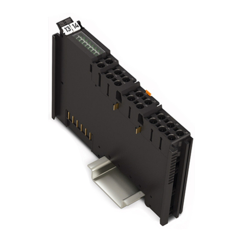
WAGO 2789-9080 User manual

Product manual | Version 1.0.0
Communication Modules
IO-Link Communication Module
2789-9080

2789-9080Legal Information
© 2023 WAGO GmbH & Co. KG
All rights reserved.
WAGO GmbH & Co. KG
Hansastraße 27
D - 32423 Minden
Phone: +49 571/887 – 0
Fax: +49 571/887 – 844169
E-Mail: * [email protected]
Internet: ü www.wago.com
Technical Support
Phone: +49 571/887 – 44555
Fax: +49 571/887 – 844555
E-Mail: * [email protected]
Every conceivable measure has been taken to ensure the accuracy and completeness of
this documentation. However, as errors can never be fully excluded, we always appreci-
ate any information or suggestions for improving the documentation.
E-Mail: * [email protected]
We wish to point out that the software and hardware terms as well as the trademarks of
companies used and/or mentioned in the present manual are generally protected by
trademark or patent.
WAGO is a registered trademark of WAGO Verwaltungsgesellschaft mbH.
Product manual | Version: 1.0.0
IO-Link Communication Module

2789-9080 Table of Contents
Product manual | Version: 1.0.0 iii
IO-Link Communication Module
Table of Contents
1Provisions ........................................................................................................................5
1.1 Intended Use ...........................................................................................................5
1.2 Typographical Conventions .....................................................................................6
1.3 Legal Information.....................................................................................................8
2Safety ................................................................................................................................9
2.1 General Safety Rules ..............................................................................................9
2.2 Electrical Safety.......................................................................................................9
2.3 Mechanical Safety ...................................................................................................9
2.4 Thermal Safety ......................................................................................................10
2.5 Indirect Safety........................................................................................................10
3Properties .......................................................................................................................11
3.1 Overview................................................................................................................11
3.2 View.......................................................................................................................11
3.3 Type label ..............................................................................................................12
3.4 Product-Specific Information .................................................................................13
3.5 Connections...........................................................................................................13
3.5.1 IO-Link..........................................................................................................13
3.6 Indicators ...............................................................................................................14
3.7 Technical data .......................................................................................................14
3.7.1 Product .........................................................................................................14
3.7.2 Input..............................................................................................................14
3.7.3 Power Loss...................................................................................................15
3.7.4 Communication.............................................................................................15
3.7.5 Environmental Requirements .......................................................................15
3.8 Guidelines, approvals and standards ....................................................................15
3.8.1 Guidelines ....................................................................................................15
3.8.2 Approvals......................................................................................................16
3.8.3 Standards .....................................................................................................16
4Fieldbus Description .....................................................................................................17
4.1 Technology ............................................................................................................17
4.1.1 IO-Link Technology ......................................................................................17
4.1.2 IO-Link – Functions ......................................................................................17
4.2 Parameters ............................................................................................................18
4.2.1 General Module Parameters ........................................................................18
4.2.2 Specific Module Parameters of the WAGO Power Supply Pro 2 ................. 19
4.2.3 Data Structure for WAGO Power Supplies Pro 2 ......................................... 19
4.2.4 Parameter Addresses for WAGO Power Supplies Pro 2 .............................20
4.2.4.1 Password Handling ............................................................................. 21
4.2.4.2 Baud Rate (Index 380) ........................................................................ 22
4.2.4.3 Data bits (Index 382)........................................................................... 22
2789-9080Table of Contents
iv Product manual | Version: 1.0.0
IO-Link Communication Module
4.2.4.4 Stop bits (Index 383) ........................................................................... 22
4.2.4.5 Parity (Index 384)................................................................................ 22
4.2.4.6 Data format (Index 386) ...................................................................... 23
4.2.4.7 Output behavior (Index 394)................................................................23
4.2.4.8 Configuration of digital input (Index 424) ............................................24
4.2.4.9 Configuration of digital output (Index 432) .......................................... 24
4.2.4.10 System/General (Index 445) ............................................................... 26
4.3 Messages and Events ...........................................................................................26
4.3.1 Error Messages for WAGO Power Supplies Pro 2....................................... 26
4.3.2 Events and Measured Values for WAGO Power Supply Pro 2 .................... 27
4.4 Other......................................................................................................................27
4.4.1 IODD for WAGO Power Supplies Pro 2 ....................................................... 27
5Transport and Storage ..................................................................................................29
6Installation and Removal ..............................................................................................30
7Decommissioning..........................................................................................................32
7.1 Disposal and Recycling .........................................................................................32
8Appendix ........................................................................................................................33
8.1 Accessories ...........................................................................................................33
8.2 Protected Rights ....................................................................................................33

2789-9080 Provisions
Product manual | Version: 1.0.0 5
IO-Link Communication Module
1Provisions
This document applies to the following product:
2789-9080 (IO-Link Communication Module)
Product detail page üwww.wago.com/2789-9080
The product must only be installed and operated in accordance with the operating instruc-
tions. Knowledge of the operating instructions is required for proper use. You can find all
documents and information on the detailed product page.
Additional document
•& Product Manual of the Pro 2 Power Supply used
•& Product Manual IO-Link Master
1.1 Intended Use
The 2789 Series IO-Link Communication Module is used for communication with an IO-
Link master and is plugged into a subordinate WAGO Power Supply Pro 2.
The product is an open type device and is designed for installation in an additional enclo-
sure.
• This product is intended for installation in automation technology systems.
• The product is designed for use in dry indoor rooms.
• Operation of the products in industrial area is permitted.
• The product meets the EMC requirements for the residential, office and commercial
area as well as small business, if the product used complies with the required emis-
sions of interference (emission limits).
• Operation of the product in other application areas is only permitted when correspond-
ing approvals and labeling are present.
Improper Use
Improper use of the product is not permitted. Improper use occurs especially in the follow-
ing cases:
• Non-observance of the intended use
• Use without protective measures in an environment in which moisture, salt water, salt
spray mist, dust, corrosive fumes, gases, direct sunlight or ionizing radiation can occur
• Use of the product in areas with special risk that require continuous fault-free operation
and in which failure of or operation of the product can result in an imminent risk to life,
limb or health or cause serious damage to property or the environment (such as the
operation of nuclear power plants, weapons systems, aircraft and motor vehicles)
Warranty and Liability
The terms set forth in the General Business and Contract Conditions for Delivery and
Service of WAGO GmbH & Co. KG and the terms for software products and products with
integrated software stated in the WAGO Software License Contract – both available at
üwww.wago.com – shall apply. In particular, the warranty is void if:

2789-9080Provisions
6 Product manual | Version: 1.0.0
IO-Link Communication Module
• The product is improperly used.
• The deficiency (hardware and software configurations) is due to special instructions.
• Modifications to the hardware or software have been made by the user or third parties
that are not described in this documentation and that has contributed to the fault.
Individual agreements always have priority.
Obligations of Installers/Operators
The installers and operators bear responsibility for the safety of an installation or a sys-
tem assembled with the product. The installer/operator is responsible for the proper in-
stallation and safety of the system. All laws, standards, guidelines, local regulations and
accepted technology standards and practices applicable at the time of installation, and
the instructions in the the products’ Instructions for Use, must be complied with. In addi-
tion, the installment requirements for licensing must be observed. In the event of non-
compliance, the product may not be operated within the scope of the approval.
1.2 Typographical Conventions
Number Notation
100 Decimals: Normal notation
0x64 Hexadecimals: C-notation
‘100’
‘0110.0100’
Binary: In single quotation marks
Nibbles separated by a period
Text Formatting
italic Names of paths or files
bold Menu items, entry or selection fields, emphasis
Code Sections of program code
> Selection of a menu point from a menu
“Value” Value entries
[F5] Identification of buttons or keys
Cross References / Links
Cross references/links to a topic in a document
Cross references / links to a separate document
ü
Cross references / links to a website
Cross references / links to an email address
Sequence of Action
üThis symbol identifies a precondition.
1. Action step
2. Action step
ðThis symbol identifies an intermediate result.
ðThis symbol identifies the result of an action.

2789-9080 Provisions
Product manual | Version: 1.0.0 7
IO-Link Communication Module
• Individual action step
Lists
• Lists, first level
– Lists, second level
Figures
Figures in this documentation are for better understanding and may differ from the actual
product design.
Warning Notices
DANGER
Type and source of hazard
Indicates an imminently hazardous situation which, if not avoided, will result in death or
serious injury.
• Action step to reduce risk
WARNING
Type and source of hazard
Indicates a potentially hazardous situation which, if not avoided, could result in death or
serious injury.
• Action step to reduce risk
CAUTION
Type and source of hazard
Indicates a potentially hazardous situation which, if not avoided, may result in minor or
moderate injury.
• Action step to reduce risk
!
NOTICE
Type and source of malfunction (property damage only)
Indicates a potentially hazardous situation which, if not avoided, may result in damage to
property.
• Action step to reduce risk

2789-9080Provisions
8 Product manual | Version: 1.0.0
IO-Link Communication Module
Information Notices
Note
Information
Indicates information, clarifications, recommendations, referrals, etc.
1.3 Legal Information
Intellectual property
The intellectual property of this document belongs to WAGO GmbH & Co. KG. The repro-
duction and distribution of its content (in whole or in part) is prohibited, unless otherwise
provided by statutory provisions, written agreements or this document. In case of doubt,
the written consent of WAGO GmbH & Co. KG must be obtained in advance.
Third-party products are always mentioned without any reference to patent rights. WAGO
GmbH & Co.KG, or the manufacturer of third-party products, retains all rights regarding
patent, utility model or design registration.
Third-party trademarks are referred to in the product documentation. The “®” and “TM”
symbols are omitted hereinafter. The trademarks are listed in the Appendix: 8Protected
Rights [}33].
Subject to Change
The instructions, guidelines, standards, etc., in this manual correspond to state of the art
at the time the documentation was created and are not subject to updating service. The
installer and operator bear sole responsibility to ensure they are complied with in their
currently applicable form. WAGO GmbH & Co. KG retains the right to carry out technical
changes and improvements of the products and the data, specifications and illustrations
of this manual. All claims for change or improvement of products that have already been
delivered – excepting change or improvement performed under guarantee agreement –
are excluded.
Licenses
The products may contain open-source software. The requisite license information is
saved in the products. This information is also available under: üwww.wago.com.

2789-9080 Safety
Product manual | Version: 1.0.0 9
IO-Link Communication Module
2Safety
2.1 General Safety Rules
• This documentation is part of the product. Therefore, retain the documentation during
the entire service life of the product. Pass on the documentation to any subsequent
user of the product. In addition, ensure that any supplement to this documentation is
included, if necessary.
• The product must only be installed and put into operation by qualified electrical special-
ists per EN 50110‑1/-2 and IEC 60364.
• Comply with the laws, standards, guidelines, local regulations and accepted technol-
ogy standards and practices applicable at the time of installation.
2.2 Electrical Safety
• Make sure the product does not carry any voltage before starting work.
Grounding/Protection/Fuses
• When handling the product, please ensure that environmental factors (personnel, work
space and packaging) are properly equalized. Do not touch any conducting parts.
Cables
• Maintain spacing between control, signal and data lines and the power supply lines.
• Observe permissible temperature range of connecting cables.
• Only clamp one conductor to each connection terminal. If several conductors must be
clamped, wire them using an upstream wiring assembly (e.g., WAGO Through Termi-
nal Blocks).
• Use appropriate strain relief.
2.3 Mechanical Safety
• As the installer of the system, you are responsible for ensuring the necessary touch-
proof protection. Follow the installation guidelines for the specific application.
• Before startup, please check the product for any damage that may have occurred dur-
ing shipping. Do not put the product into operation in the event of mechanical damage.
• Do not open the product housing.
• The product is an open-type device and is designed for installation in an additional en-
closure, which supplies the following safety aspects:
– Restrict access to authorized personnel and may only be opened with tools.
– Ensure the required pollution degree in the vicinity of the system.
– Offer adequate protection against direct or indirect contact.
– Offer adequate protection against UV irradiation.
– Prevent fire from spreading outside of the enclosure.
– Guarantee mechanical stability.

2789-9080Safety
10 Product manual | Version: 1.0.0
IO-Link Communication Module
2.4 Thermal Safety
• The surface of the housing heats up during operation. Under special conditions (e.g., in
the event of a fault or increased surrounding air temperature), touching the product
may cause burns. Allow the product to cool down before touching it.
• The temperature inside the additional enclosure must not exceed the surrounding air
temperature permitted for the mounted product.
• Cooling of the product must not be impaired. Ensure air can flow freely and that the
minimum clearances from adjacent products/areas are maintained.
2.5 Indirect Safety
• Only use a dry or cloth or a clothed dampened with water to clean the product. Do not
use cleaning agents, e.g., abrasive cleaners, alcohols or acetone.
• Clean tools and materials are imperative for handling the product.
• The product contains no parts that can be serviced by the user. Always have all ser-
vice, maintenance and repair work performed by specialists authorized by WAGO.
• Replace any defective or damaged devices.

2789-9080 Properties
Product manual | Version: 1.0.0 11
IO-Link Communication Module
3Properties
3.1 Overview
IO-Link is a communication system for connecting intelligent sensors and actuators to an
automation system. This communication system is defined in the IEC 61131-9 standard
(see 8IO-Link Technology [}17]).
The IO-Link Communication Module enables communication with an IO-Link master. It is
plugged onto the communication interface that is integrated on the front of the WAGO
Power Supply Pro 2. You can find more information in the & Product Manual IO-Link
Master.
3.2 View
a
c
e
g
b
h
b
f
Figure1: View
Position Comment Details
a Locking tab –
b Ventilation openings –
c Optical Status Indicator 8Indicators [}14]
e Communication interface –
f Type label 8Type label [}12]
g Marker carrier 8Accessories [}33]
h IO link (X5) 8IO-Link [}13]

2789-9080Properties
12 Product manual | Version: 1.0.0
IO-Link Communication Module
3.3 Type label
The product’s type plate contains the following information:
Figure2: Type label
Pos. Comment Details
1 Box for approvals 8Approvals [}16]
2 Item Number
3 Company logo and address
4 Product name
5 QR link with link to website
6 Reference to product documentation
7 Product-specific information
See also
2Approvals [}16]
2Product-Specific Information [}13]
2Typographical Conventions [}6]

2789-9080 Properties
Product manual | Version: 1.0.0 13
IO-Link Communication Module
3.4 Product-Specific Information
Figure3: Product-Specific Information
Position Comment Details
1 2D data matrix code Contains the information for positions 2
… 5
2 Key number Fixed information (37S)
3 ID number per D-U-N-S® Fixed information (WAGO Minden)
4 WAGO item number or internal SAP number Product-specific
5 Consecutive number Product-specific
6 Production date and revision • Production date
• Revision index (FW HW FL)
7 Internal manufacturer product number Product-specific
8 Media Access Control Identifier Product-specific
Table1: Revision index structure
Software index Hardware index Boot loader index
FW HW FL
3.5 Connections
3.5.1 IO-Link
1 2 3
4
Figure4: IO-Link X5 port
Pos. Pin Description
1 1 Contact “L+” for input voltage
2 2 “C/Q” contact
3 3 “L-” contact for input voltage
4 – Test slot
Table2: Details – IO-Link Port
Series 721

2789-9080Properties
14 Product manual | Version: 1.0.0
IO-Link Communication Module
Item Number 0721-0103/Z000-0020
Connection Technology Push-In CAGE CLAMP®
3.6 Indicators
The product has a visual status indicator. This indicator consists of two LEDs.
ERR
COM OK
Figure5: Visual Status Indicator
Table3: Operating Status Indication
Indicator LED Description State Description
ERR Error Off Ready for operation; no error
On General error/system error
Flashing (2Hz) IO‑Link connection error
Flashing (8Hz) Connection error to the lower-level device
COM OK Device status Off No connection to lower-level device
On Ready for operation
Flashing (2Hz) Communication active
3.7 Technical data
3.7.1 Product
Table4: Technical Data – Product
Property Value
Width 35 mm
Height 80 mm / 95 mm (incl. connector/female connec-
tor)
Depth 22 mm / 28 mm (incl. latch)
Weight 35g
Degree of protection IP20
3.7.2 Input
Table5: Technical Data – Input
Property Value
Nominal input voltage 24 VDC SELV (via IO-Link master)
Input voltage range 18 … 30 VDC SELV (via IO-Link master)
Input current ≤ 15mA
Table6: Technical Data – Input Connection
Property Value
Cross-section Solid 0.08…2.5mm² / 28…12AWG
Fine-stranded 0.08…2.5mm² / 28…12AWG
Insulated ferrule with plastic collar 0.25…1.5mm² / 20…16 AWG
Ferrule without plastic collar 0.25…2.5mm² / 20…14AWG
Strip length 8 … 9mm / 0.31 … 0.35inch

2789-9080 Properties
Product manual | Version: 1.0.0 15
IO-Link Communication Module
Property Value
Required tools (conductor termination) Operating tool, with a partially insulated shaft,
type 2 (see 8Accessories [}33])
3.7.3 Power Loss
Table7: Technical Data – Power Loss
Property Value
Power loss (max.) 0.36W
3.7.4 Communication
Table8: Technical Data – Communication
Property Value
Baud rate 230.4 bit/s (COM 3)
Length PDIN 5bytes
Length PDOUT 1 byte
IO-Link Version 1.1.2
SIO No
Data Storage Yes
Block parameterization Yes
Interlock DS Lock, Parameter Access Lock
Profiles Common Profile v1.0
3.7.5 Environmental Requirements
Table9: Technical Data – Environmental Conditions
Property Value
Test voltage (input/output) 1.8kVAC, 50Hz, 1min
Type of insulation Functional insulation
Ambient temperature, operation −25 … +70°C
Ambient temperature, storage −40 … +85°C
Relative humidity 5 … 96 % (no condensation)
Operating altitude above sea level, max. 5000m
Overvoltage category1III
Pollution degree according to IEC/EN60664-1 2
Protection class III (when protective low voltage [SELV] is present
via the IO-Link Master)
Protection type1IP20
Isolation 0.63kV
1 The lower-level WAGO Power Supply Pro 2
3.8 Guidelines, approvals and standards
3.8.1 Guidelines
An EU “Declaration of Conformity” and CE marking exist for the product.
For additional information, visit üwww.wago.com.

2789-9080Properties
16 Product manual | Version: 1.0.0
IO-Link Communication Module
3.8.2 Approvals
The following approvals have been granted for the product:
Table10: Approvals
Logo Certification Body Standard
Underwriters Laboratories UL 61010-1
Underwriters Laboratories UL 61010-2-201
Underwriters Laboratories UL 121201,
Class I, Division 2, Groups A B C D, T4
3.8.3 Standards
Table11: Mechanical and Climatic Environmental Conditions
Standard Test Value
Mechanical Environmental Conditions
EN 60068-2-6 f = 5 …150Hz: 1g, 3.5m
IEC 60068-2-27 shock 15g, 11ms, 6 shocks per axis and direction, half-sine
EN61131-2, Section 4.3 Freefall ≤ 300mm (packaged in the product packaging)
Climatic Environmental Conditions
EN 60870-2-2 3K3 (except for low air pressure)
Table12: EMV – Immunity to Interference
Standard Title
EN 61000-6-2 Part 6-2: Generic standards – Immunity for industrial environments
EN 61000-4-2 Part 4-2: Testing and measurement techniques – Electrostatic discharge im-
munity test
EN 61000-4-3 Part 4-3: Testing and measurement techniques – Radiated, radio-frequency,
electromagnetic field immunity test
EN 61000-4-4 Part 4-4: Testing and measurement techniques – Electrical fast transient/
burst immunity test
EN 61000-4-6 Part 4-6: Testing and measurement techniques – Immunity to conducted dis-
turbances, induced by radio-frequency fields
EN 61000-4-8 Part 4-8: Testing and measurement techniques – Power frequency magnetic
field immunity test
Table13: EMC – Emission of Interference
Standard Title
EN 61000-6-3 Part 6-3: Generic standards – Emission standard for residential, commercial
and light-industrial environments

2789-9080 Fieldbus Description
Product manual | Version: 1.0.0 17
IO-Link Communication Module
4Fieldbus Description
4.1 Technology
4.1.1 IO-Link Technology
IO-Link defines a communication standard (acc. IEC 61131-9) for connecting both current
digital outputs/outputs and intelligent IO-Link devices to the controller level. IO-Link de-
vices describe sensors and actuators of the field level that have IO-Link functionality.
The IO-Link technology is predominantly used in the industrial sector of manufacturing
automation. With IO-Link, configuration, diagnostics and maintenance from the controller
are possible to the lowest field level in addition to process data communication. For ex-
ample, sensor failures can be diagnosed and localize in the controller directly.
With central parameter data storage in the IO-Link master and the possibility of project
development, connected devices can be simply replaced and configurations copied.
Communication occurs via serial point-to-point links in standard -3-wire technology. Both
data and diagnostic information as well as power supply are carried over the serial IO-
Link interface simultaneously.
Figure6: 3-Wire Connection Technology (Based on Physics 2 of the IO-Link Specification 1.0.0)
Configuration of IO-Link devices is based on standardized description files “IO Device
Description” (IODD), which are provided by the device manufacturers and imported into
the respective configuration software. Thus, IO-Link devices can be integrated in current
automation systems and network structures independent of the bus systems used.
4.1.2 IO-Link – Functions
The production has the following functions:
• Reading the current settings from the lower-level device.
• Cyclic reading of the status from the lower-level device.
• Writing settings on the lower-level device.
• Controlling the lower-level device.
• Implementing the “Common Profiles” from IO-Link into the product.

2789-9080Fieldbus Description
18 Product manual | Version: 1.0.0
IO-Link Communication Module
4.2 Parameters
4.2.1 General Module Parameters
The product uses the following default IO-Link parameters:
Table14: Standard parameters of IO-Link
Index Parameters Data Type Datenlänge
(Bytes)
Description
12 Device Access
Locks
RecordT 2 Standardized Device locking functions
13 Profile
Characteristic
ArrayT of
UIntegerT16
2 Profile characteristic
14 PDInput Descriptor ArrayT of
OctetStringT3
3 Reserved for Device profile
15 PDOutput
Descriptor
ArrayT of
OctetStringT3
3 Reserved for Device profile
16 Vendor Name StringT 32 Informative
17 Vendor Text StringT 32 Additional vendor information
18 Product Name StringT 32 Detailed product or type name
19 Product ID StringT 32 Product or type identification
21 Serial Number StringT 16 Description of Device function or characteristic
22 Hardware Revision StringT 5 Vendor specific serial number
23 Firmware Revision StringT 8 Vendor specific format
24 ApplicationSpecific
Tag
StringT 32 Vendor specific format
25 Function Tag StringT 32 Tag location or tag function defined by user
26 Location Tag StringT 32 Standardized Device locking functions
36 Device Status UIntegerT 1 Contains current status of the Device
37 Detailed Device
Status
ArrayT of
OctetStringT3
96
40 ProcessDataInput 32 Read last valid Process Data from PDin channel
41 ProcessDataOut-
put
32 Read last valid Process Data from PDout channel
For more information on these default parameters, see:
• IO-Link Interface and System Specification Version 1.1.2 Table B.8
• IO-Link Common Profile Specification Version 1.0 Table B.1

2789-9080 Fieldbus Description
Product manual | Version: 1.0.0 19
IO-Link Communication Module
4.2.2 Specific Module Parameters of the WAGO Power Supply Pro 2
The product uses the following WAGO-specific parameters:
Table15: WAGO-Specific Parameters
Index Parameters Data Type Data length
(bytes)
Description
12001 Part number mod-
ule
StringT 8 Module item number
12002 Part number ex-
tension (module)
StringT 8 Item number extension of the module
12003 Hardware version
module
StringT 2 HW Release Index of the module in the “XX” for-
mat
12004 Firmware version
module
StringT 8 FW Revision of the module in the “XX.XX.XX” for-
mat
12005 Configuration ID
module
UIntegerT 4 Configuration ID of the module
4.2.3 Data Structure for WAGO Power Supplies Pro 2
The product has the following structure:
• 5-byte input process data
• 1-byte output process data
The structure of the input and output process data is explained below.
Input Process Data
The product has the following input process data (5 bytes):
Table16: Process Data Structure
Byte Description
0 Status messages (see Table “Status Message Structure”)
1 … 2 Measured output current 0.000…65.535A in steps of 1mA
3 … 4 Measured output voltage 0.000…65.535V insteps of 1mV
Table17: Status Message Structure
Bit Description
0 DC OK
Set when the output voltage is OK.
1 Overtemperature shutdown T≥Tmax
2 No output voltage
3 Short circuit at output
4 Digital output set
5 … 7 Reserved
Output Process Data
The product has the following output process data (1 byte):
Table18: Control Data Structure
Bit Description
0 Set device to standby
1 Set DO
2 … 7 Reserved

2789-9080Fieldbus Description
20 Product manual | Version: 1.0.0
IO-Link Communication Module
4.2.4 Parameter Addresses for WAGO Power Supplies Pro 2
Table19: Parameter Addresses
Index Parameter Access Data type Data length
(bytes)
Description
340 Password write only StringT 8 Password (see 8Password Handling
[}21])
348 Password protec-
tion level
Read/write UIntegerT 2 Password protection (for selection options,
see 8Password Handling [}21])
378 Device address Read/write UIntegerT 2 Device ID
379 Termination Read/write UIntegerT 2 No termination
380 Baud rate Read/write UIntegerT 4 Baud rate (for selection options, see
8Baud Rate (Index 380) [}22])
382 Data bits Read/write UIntegerT 2 Data bits (for selection options, see
8Data bits (Index 382) [}22])
383 Stop bits Read/write UIntegerT 2 Stop bits (for selection options, see
8Stop bits (Index 383) [}22])
384 Parity Read/write UIntegerT 2 Parity (for selection options, see 8Parity
(Index 384) [}22])
385 Response delay Read/write UIntegerT 2 Time between receive and respond
386 Data format Read/write UIntegerT 2 Data format (for selection options, see
8Data format (Index 386) [}23])
392 Output voltage Read/write UIntegerT 2 Requested output voltage
393 Overload warning
threshold
Read/write UIntegerT 2 Overload threshold between >0A and
rated current.
394 Output Behavior Read/write UIntegerT 2 Behavior settings (for selection options,
see 8Output behavior (Index 394)
[}23])
395 Switch-on delay Read/write UIntegerT 2 User-configurable switch-on delay (waiting
time between AC mains voltage is applied,
i.e., the processor has booted and power
stages are switched on).
404 Trip current Read/write UIntegerT 2 User-configurable threshold between 10 %
of rated current and rated current.
405 Trip delay Read/write UIntegerT 2 Circuit breaker function:
User-configurable time how long an over-
current is ignored.
100ms to 60000ms
424 Signalization
Configuration of dig-
ital input
Read/write UIntegerT 2 Digital input behavior settings (for selec-
tion options, see 8Configuration of dig-
ital input (Index 424) [}24])
432 Signalization
Configuration of dig-
ital output
Read/write UIntegerT 2 Digital output behavior settings (for selec-
tion options, see 8Configuration of dig-
ital output (Index 432) [}24])
444 Operating hours
counter threshold
Read/write UIntegerT 2 Digital output behavior settings (for selec-
tion options, see 8Configuration of dig-
ital output (Index 432) [}24])
445 System/General Read/write UIntegerT 2 Behavior settings and system parameters
(for selection options, see 8System/
General (Index 445) [}26])
Table of contents
Other WAGO Control Unit manuals

WAGO
WAGO I/O-SYSTEM 751-3002 User manual

WAGO
WAGO 750-509 User manual

WAGO
WAGO 750-539 User manual

WAGO
WAGO 750-468/040-000 User manual

WAGO
WAGO 750-1405/040-000 User manual

WAGO
WAGO 750-517/040-000 User manual

WAGO
WAGO 750-430/040-000 User manual

WAGO
WAGO 751-5702 User manual

WAGO
WAGO WAGO-TO-PASS 761 User manual

WAGO
WAGO 750-564 User manual

WAGO
WAGO 750-1605/040-000 User manual

WAGO
WAGO 751-5202 User manual

WAGO
WAGO 750-1504 User manual

WAGO
WAGO SPEEDWAY 767 Series User manual

WAGO
WAGO 753-466 User manual

WAGO
WAGO WAGO-I/O-SYSTEM 750-508 User manual

WAGO
WAGO 750-477 User manual

WAGO
WAGO 750-363/0040-0000 User manual

WAGO
WAGO 2789-9023 User manual

WAGO
WAGO 4FDI 24V PROFIsafe V2.0 Product guide