Universal Audio Apollo User manual

Hardware Manual
UA Part Number 65-40424
Revision A
Customer Service & Technical Support:
+1-877-MY-UAUDIO (+1-877-698-2834)
International: +1-831-440-1176
www.uaudio.com
H I GH- R ESO L U T I O N INTER F A C E
with Realtime UAD Processing

Apollo Hardware Manual Welcome
ii
A Letter from Bill Putnam Jr.
Thank you for deciding to make Universal Audio’s Apollo High-Resolution Interface with Realtime UAD
Processing part of your music making experience. We know that any new piece of gear requires both an
investment in time and money — our goal is to make your investment pay off. The fact that we get to play a
part in the creativity of folks like yourself is what makes our efforts at UA meaningful, and for your part in this
and your faith in us we thank you.
In many ways, Apollo represents the single best example of what UA has stood for over its long history; from
UA’s original founding in the 1950s by my father, up through our current vision of delivering the best of both
analog and digital audio technology. During these many years, UA has produced some of the most coveted
pieces of analog recording equipment. Additionally, we have pioneered cutting edge digital signal processing
which has allowed us to offer the most exacting digital versions of classic analog hardware. Our unique
expertise and experience across both analog and digital have allowed us to make something that we think is
very special.
Starting with a high-quality analog front end, Apollo’s sonic performance serves as the foundation. This is just
the start however, as Apollo is the only audio interface that allows you to run UAD plug-ins in realtime, allowing
you to track and monitor using any of our plug-ins. Want to monitor yourself through a Neve console channel
strip while tracking your bass through a Fairchild or LA-2A compressor? Or how about tracking vocals through
an SSL Channel Strip with some added Lexicon reverb? No problem — this is something only Apollo offers.
At UA we have a firm belief and dedication to the idea that technology ultimately should serve the creative
process — not be a barrier. These are the very ideals my father embodied as he invented audio equipment to
solve problems in the studio. Growing up, my father taught me that technology should be easy to use, and not
get in the way. With this in mind we have crafted the Apollo Console software with an ‘analog workflow.’ We
feel that the convenience of the Console workflow, along with innovations such as the Console Recall plug-in,
offer ease-of-use and DAW integration that will provide you with a unique and productive experience.
As you get to know Apollo and incorporate it into your creative process, we hope that the excitement and pride
that we have put into it comes through. We also hope that it earns its way into your creative process, providing
you great sound, great plug-ins, and ease-of-use for years to come. Thanks!
Sincerely,
Bill Putnam Jr.

Apollo Hardware Manual Table Of Contents
iii
Table Of Contents
A Letter from Bill Putnam Jr. ................................................................................................................................ii
Introducing Apollo ................................................................................................................................................4
What is Apollo?................................................................................................................................................4
Apollo Features................................................................................................................................................5
Hardware System Requirements......................................................................................................................6
About Realtime UAD Processing ......................................................................................................................7
Combining with other UAD-2 devices ..............................................................................................................7
Standalone Use................................................................................................................................................7
About Apollo Documentation............................................................................................................................7
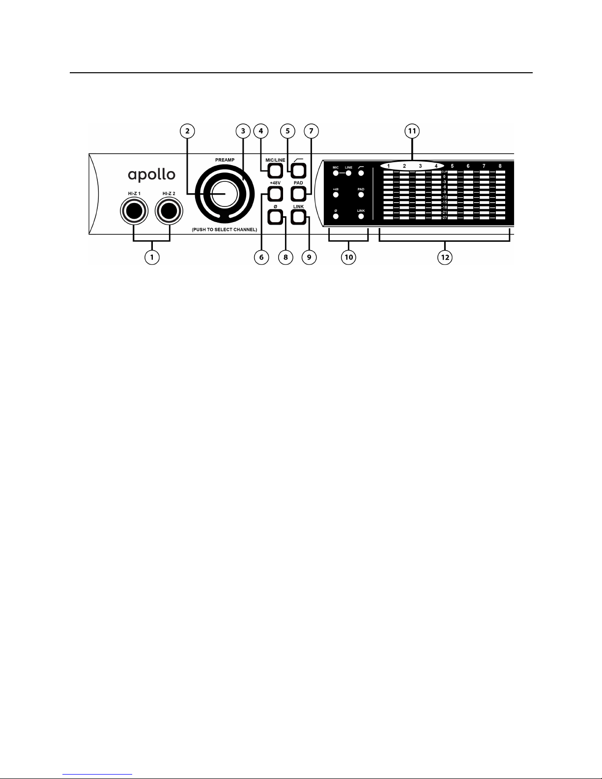
Front Panel...........................................................................................................................................................9
Rear Panel..........................................................................................................................................................13
Analog I/O......................................................................................................................................................13
Digital I/O......................................................................................................................................................14
Host I/O..........................................................................................................................................................16
Software Installation..........................................................................................................................................17
Registration & Authorization ..............................................................................................................................18
Device Driver Setup ............................................................................................................................................19
Console Settings Window...............................................................................................................................19
Global Interface Settings...............................................................................................................................19
DAW Settings.................................................................................................................................................20
Interconnections.................................................................................................................................................21
Installation Notes ..........................................................................................................................................21
Basic Setup ...................................................................................................................................................21
Typical Setup.................................................................................................................................................22
Advanced Setup.............................................................................................................................................23
FireWire Basics...................................................................................................................................................24
Mixing FireWire Speeds..................................................................................................................................26
Recommended Mixed Speed Setup ................................................................................................................26
Digital Clocking Basics ......................................................................................................................................27
Specifications ....................................................................................................................................................29
Hardware Block Diagram....................................................................................................................................33
Troubleshooting..................................................................................................................................................34
Additional Resources..........................................................................................................................................35
Universal Audio Website ................................................................................................................................35
Technical Support..........................................................................................................................................35
Maintenance..................................................................................................................................................35
Voltage Selection...........................................................................................................................................35
Warranty........................................................................................................................................................36
Repair Service ...............................................................................................................................................36
Notices ...............................................................................................................................................................37
Important Safety Information ........................................................................................................................37
Index ..................................................................................................................................................................39

Apollo Hardware Manual Introducing Apollo
4
Introducing Apollo
What is Apollo?
Apollo is a high-resolution audio interface with Realtime UAD processing onboard that gives musicians and
recording engineers a no-compromise monitoring, tracking, and mixing solution. The combination of Apollo’s
high quality preamps, converters, and digital signal processing help you achieve the goal of making music
without the common latency and potential processor shortcomings of an all-native system. Apollo leverages
Universal Audio’s expertise in DSP acceleration, UAD Powered Plug-Ins, and analog hardware design by
integrating the latest cutting edge technologies in high-performance A/D-D/A conversion, DSP signal
reconstruction, and host connectivity. Apollo acts as both an audio interface with integrated DSP effects for
tracking and monitoring as well as a fully integrated UAD-2 DSP accelerator for mixing and mastering.
Apollo is available in two different configurations, which are differentiated by their DSP complement: Apollo
DUO with 2 SHARC DSPs, and Apollo QUAD with 4 SHARC DSPs. Apollo DUO and QUAD have identical I/O
features and functionality; the only difference is how much simultaneous plug-in processing that is available
for tracking and mixing. Either way, you have an amazing sounding interface that can achieve the professional
sound quality of any era in recording history by using UAD Powered Plug-Ins.
Apollo uses FireWire or Thunderbolt for computer connectivity. FireWire 800 doubles the performance of FireWire
400 and ensures the ability to use all of Apollo’s I/O as well as its DSP processing. Thunderbolt is a high-speed
data transmission protocol that provides faster throughput than FireWire. The Thunderbolt Option Card can be
easily installed in Apollo’s option card slot allowing Apollo to connect with Thunderbolt-enabled computers.
To fully realize the low latency potential of Apollo, the Console application is included and provides a familiar
analog mixing console interface where you can load your favorite combination of Realtime UAD plug-ins.
Setting up two custom headphone mixes is quick and intuitive and you can also set up reverbs and delays (or
any other UAD effects) on two auxiliary buses for comfortable tracking of live microphones and instruments.
Achieving deep integration of Apollo’s features with your favorite audio workstation software is simple thanks
to the Console Recall plug-in that is compatible with VST, Audio Units, and RTAS host software. Simply place
the Console Recall plug-in in any session and you have instant control over Apollo’s monitoring, headphones,
and Realtime UAD plug-in wet/dry options. A single button on the plug-in will automatically recall the Console
configuration within the DAW session without having to manage separate Console preset files, so you can be
sure that the Console mix you are working with today will be accurately recalled tomorrow.
Done tracking? Use Apollo just like any other UAD-2 device for mixing in the DAW. The full UAD Powered Plug-
Ins library works with Apollo, offering the best analog emulation plug-ins available from the best companies in
pro audio like Neve, SSL, Pultec, Teletronix, Studer, Lexicon, DBX, Roland, MXR, Harrison, Empirical Labs,
Manley, Ampex, and many more. A single button in the Console lets you decide to “print” or “monitor” the
Realtime UAD plug-ins – so if you want the sound of your favorite console and tape machine committed into
your DAW, you can print those effects on the way in.
Quite simply, Apollo delivers the sound, feel, and flow of analog recording with all the conveniences of modern
digital equipment.

Apollo Hardware Manual Introducing Apollo
5
Apollo Features
•Superior-sounding 18 x 24 audio interface with uncompromising UA analog design
•Realtime monitoring and tracking with premium UAD Powered Plug-Ins
•Additional mixing and mastering DSP horsepower for your sessions
•FireWire 800 built-in; user-installable Thunderbolt I/O option card (not included)
Audio Interface
•Sample rates up to 192 kHz at 24-bit word length
•18 x 24 simultaneous input/output channels:
•Eight channels of analog-to-digital conversion via mic, line, or high-impedance inputs
•14 channels of digital-to-analog conversion via:
•Eight mono line outputs
•Stereo monitor outputs
•Two stereo headphone outputs
•10 channels of digital I/O via:
•Eight channels ADAT Optical I/O with S/MUX for high sample rates
•Two channels coaxial S/PDIF I/O with sample rate conversion
•Two FireWire 800 ports for daisy-chaining other FireWire devices
•32-bit and 64-bit device drivers
Microphone Preamplifiers
•Four high-resolution, ultra-transparent, digitally-controlled analog mic preamps
•Front panel and software control of all preamp parameters
•Switchable low cut filter, 48V phantom power, 20 dB pad, polarity inversion, and stereo linking
Monitoring
•Stereo monitor outputs (independent of eight line outputs)
•Digitally-controlled analog monitor outputs maintains highest fidelity
•Front panel control of monitor levels and muting
•Two stereo headphone outputs with independent mix buses
•Independent front panel analog volume controls for headphone outputs
•Front panel pre-fader metering of monitor bus levels
•S/PDIF outputs can be set to mirror the monitor outputs
UAD-2 Inside
•DUO and QUAD models featuring two or four SHARC processors
•Realtime UAD Powered Plug-Ins processing on all of Apollo’s analog and digital inputs
•Same features and functionality as other UAD-2 products when used with DAW
•Can be combined with other UAD-2 devices for increased mixing DSP
•Includes UAD Powered Plug-Ins “Analog Classics” bundle
•Complete UAD-2 Powered Plug-Ins library is available online 24/7

Apollo Hardware Manual Introducing Apollo
6
Software
•Console application:
•Enables Realtime UAD Powered Plug-Ins processing
•DSP mixer for realtime monitoring and tracking
•Remote control of all Apollo features and functionality
•Console Recall plug-in:
•Saves Apollo configurations inside DAW sessions for easy recall
•Enables control of all front panel parameters from within the DAW
•VST, RTAS, and Audio Units plug-in formats
•UAD Meter & Control Panel application:
•Configures global UAD-2 and Powered Plug-Ins settings and monitors system usage
Other
•Easily updatable firmware
•1U rack-mountable form factor
•One year warranty includes parts and labor
Hardware System Requirements
The host computer must meet the hardware system requirements below to use Apollo. For software system
requirements, refer to the Apollo Software Manual (see page 7).
Basic audio interface I/O functionality:
•Available FireWire 800 or Thunderbolt* expansion port
*Thunderbolt connections require the Thunderbolt Option Card (not included)
•512 MB RAM (1 GB or higher is strongly recommended)
•1 GB available hard drive space
•CD-ROM drive or Internet connection for software installation
UAD-2 and Realtime UAD Powered Plug-Ins functionality:
•Internet connection for registration, UAD plug-in authorization, & updates
•Compatible VST, RTAS, or Audio Units plug-in host application software

Apollo Hardware Manual Introducing Apollo
7
About Realtime UAD Processing
Apollo has the ability to run UAD Powered Plug-Ins in realtime. Apollo’s groundbreaking DSP + FPGA technology
enable UAD Powered Plug-Ins to run with latencies in the sub-2ms range, and multiple UAD-2 plug-ins can be
“stacked” in series without incurring additional latency. Realtime UAD processing facilitates the ultimate sonic
experience while monitoring and/or tracking.
Realtime UAD processing is a special function that is available only within the Console application. All of
Apollo’s analog and digital inputs can perform Realtime UAD processing simultaneously, and Console inputs
with Realtime UAD processing can be routed into the DAW for recording.
Important: Apollo, like other UAD-2 devices, can only load UAD Powered Plug-Ins which are specifically
designed to run on UAD-2 DSP accelerators. “Native” plug-ins cannot run on the UAD-2 DSP.
Combining with other UAD-2 devices
Apollo can be used simultaneously with other UAD-2 devices (PCIe, SOLO/Laptop, and/or Satellite) in the same
host computer system. Apollo simply adds to the DSP availability when used with other UAD-2 devices,
increasing the DSP processing power so more UAD Powered Plug-Ins can be used. Up to four UAD-2 devices can
be combined in the same system.
Standalone Use
Although the Console application is required to unleash the full power of Apollo, the unit can be used as a
digital mixer with limited functionality without a FireWire or Thunderbolt connection to a host computer.
All currently active I/O assignments, signal routings, and monitor settings are saved to internal firmware when
Apollo is powered down, and recalled when power is re-applied. Therefore the last-used settings are always
available even when a host computer is not used.
Note that UAD-2 Powered Plug-In instantiations are not retained on power down, because the plug-in files
reside in the host computer. However, if UAD-2 plug-ins are active when Apollo’s connection to the host system
is severed, the current UAD-2 plug-in configurations remain active for processing until Apollo is powered down.
About Apollo Documentation
Documentation for all Apollo components is extensive, so instructions are separated by area of functionality, as
detailed below. All documentation is on the disk included in the retail package and is copied to the boot drive
during software installation (Apollo documentation can also be downloaded from our website).
Apollo Hardware Manual
The Apollo Hardware Manual (available in print and PDF) contains complete information about the audio
interface hardware. Included are detailed descriptions for all Apollo hardware features, control functions, and
connections. Refer to the Hardware Manual (you’re reading it now) to learn all about interfacing the hardware
with other devices, operating the panel controls, clocking, specifications, and related information.
Apollo Software Manual
The Apollo Software Manual (PDF only) contains detailed information about how to configure and control Apollo-
specific software features using the Console application and Console Recall plug-in. Refer to the Apollo
Software Manual to learn how to operate these essential software tools and integrate Apollo’s audio interface
functionality into the DAW environment.

Apollo Hardware Manual Introducing Apollo
8
UAD System Manual
The UAD System Manual (PDF only) is the complete operation manual for Apollo’s UAD-2 functionality and
applies to the entire UAD product line. It contains detailed information about installing and configuring UAD
devices, the UAD Meter & Control Panel application, how to use UAD Powered Plug-Ins within a DAW, obtaining
optional plug-in licenses at the UA online store, and more. It includes everything about UAD except Apollo-
specific information and individual UAD Powered Plug-In descriptions.
UAD Plug-Ins Manual
The features and functionality of all the individual UAD Powered Plug-Ins is detailed in the UAD Plug-Ins
Manual (PDF only). Refer to this document to learn about the operation, controls, and user interface of each
plug-in. It does not contain any system-related or integration information.
Host DAW Documentation
Each host DAW application has its own particular methods for configuring audio interfaces and using plug-ins.
Refer to the host DAW documentation for specific instructions about using audio interface and plug-in features
within the DAW.
Support Pages
The latest technical information about Apollo is posted on the Universal Audio support website. Our support
pages may contain updated, late-breaking information that is not available in other publications. The URL of
our support site is:
•www.uaudio.com/support
Technical Support
Universal Audio provides free customer support to all registered Apollo users. Our support specialists are
available to assist you via email and telephone during our normal business hours, which are from 9am to 5pm,
Monday through Friday, Pacific Standard Time.
Telephone
USA toll-free: +1-877-MY-UAUDIO (1-877-698-2834)
International: +1-831-440-1176
FAX: +1-831-461-1550
Online Support
To request online support via email, please visit our main support page at the URL above, then click the
“Submit Support Ticket” button on the right side of the loaded page to create a help ticket.

Apollo Hardware Manual Front Panel
9
Front Panel
This section describes the features and functionality of all controls and visual elements on the Apollo front
panel. Note that all front panel functions, except the headphone volume knobs and power switch, can be
controlled remotely with the Console software application.
(1) Hi-Z Inputs 1 & 2
The Hi-Z (high impedance) JFET direct inputs are for connecting low-level passive devices such as electric
guitar and bass instruments into channels 1 & 2 for A/D conversion. Connect only ¼” unbalanced TS phone
plugs to these inputs; TRS plugs cannot be used.
The Hi-Z inputs have an ultra-high input impedance of 2.2 Megohms that eliminates impedance loading,
preserving the high-frequency content of signals from sources with high impedance outputs (such as electric
guitar pickups). Hi-Z input gain levels are adjusted with the Preamp control for the associated channel.
Automatic Input Detection
Hi-Z inputs 1 & 2 use the same A/D converter channels as the corresponding Mic 1 & 2 and Line 1 & 2 inputs.
When a device is plugged into a Hi-Z input, the Mic and Line inputs for the channel are overridden, the Mic/Line
switch for the channel has no effect, and the stereo link is severed (if active). To use Mic or Line inputs 1 or 2,
its corresponding Hi-Z input must be disconnected.
(2) Preamp Gain & Channel Select Knob
This “endless” rotary encoder with integrated pushbutton serves two functions. Rotating the knob adjusts the
preamp gain for the selected input channel, and pushing the knob selects which preamp channel (1 – 4) is
affected by the front panel preamp controls.
Preamp Gain
The preamp gain of analog inputs 1 – 4 is adjusted with this control. The channel to be adjusted (1 – 4) is set
with the Channel Select function. The input to be adjusted (Mic, Line, or Hi-Z) is determined by the state of the
channel’s Mic/Line switch or Hi-Z input (if connected).
Rotating the knob clockwise increases the preamp gain for the selected channel. The available gain range for
preamp channels 1 – 4 is 10 dB to 65 dB for the Mic, Line, and Hi-Z inputs.
The response of the Preamp Gain Knob is not linear; it takes more than a full revolution of the control to move
through the available range. This increases the control resolution for more precise preamp gain adjustments.
Only analog inputs 1 – 4 have input gain adjustment via the mic preamp controls. To adjust signal levels for
inputs 5 – 18, use the output level controls of the devices that are connected to those inputs.
Channel Select
Pushing the Preamp Knob changes the currently selected channel, which determines which input (1 – 4) is
adjusted by the front panel preamp controls. A channel is selected for adjustment when its Channel Select
Indicator LED (located above the channel 1 – 4 input meters; see #11 on page 11) is illuminated.

Apollo Hardware Manual Front Panel
10
Each time the knob is pushed, the selected preamp channel is incremented. If stereo linking is active, the
stereo pairs are selected.
(3) Preamp Gain Level Indicator
The amount of preamp gain for the selected channel is displayed with the ring of illuminated green indicator
LEDs surrounding the Preamp Knob.
The LEDs are relative levels and are not calibrated to indicate any specific dB value. However, precise
numerical dB gain values for the preamps are displayed in the Console application.
(4–9) Preamp Settings
This set of six buttons control the preamp options for input channels 1 – 4. Press the buttons to toggle the
setting. The current state of each preamp option button is indicated by the Preamp Options LEDs (#10 on page
11). Each button function is detailed below.
(4) Mic/Line
This button switches between the channel’s Mic and Line inputs on the rear panel. This button has no effect if
the channel’s Hi–Z input is connected (when a cable is inserted into the Hi-Z input, the Mic/Line LED turns off).
(5) Low Cut Filter ( )
When enabled, the channel’s input signal passes through a low cut (high pass) filter. This 2nd-order coincident-
pole filter has a cutoff frequency of 75 Hz with a slope of 12 dB per octave.
The Low Cut filter affects the Mic, Line, and Hi-Z inputs. Low Cut is typically used to eliminate rumble and
other unwanted low frequencies from the input signal.
(6) Phantom Power (+48V)
When enabled, 48 volts of phantom power is supplied to the channel’s rear panel Mic input. Most modern
condenser microphones require 48V phantom power to operate. This option can only be activated when the
Mic/Line switch (#4) is set to Mic.
Note: Depending on the current configuration of the hardware and software, there may be a delay when
changing the 48V state to minimize the clicks/pops that are inherent when engaging phantom power. The
+48V LED will blink rapidly during any delay.
(7) Pad
When enabled, the channel’s microphone input signal level is attenuated by 20 dB. Pad does not affect the Line
or Hi-Z inputs.
Pad is used to reduce signal levels when overload distortion is present at low preamp gain levels, such as when
particularly sensitive microphones are used on loud instruments, and/or if the A/D converter is clipping.
(8) Polarity (ø)
When enabled, the polarity (aka “phase“) of the input channel’s signal is inverted. Polarity affects the Mic,
Line, and Hi-Z inputs.
Polarity inversion can help reduce phase cancellations when more than one microphone is used to record a
single source.
(9) Stereo Link
This button links the preamp controls of adjacent channels together (1 & 2 or 3 & 4) to create stereo input
pairs. When channels are linked as a stereo pair, any preamp control adjustments will affect both channels of
the stereo signal identically.
Only the same type of inputs can be linked (Mic/Mic or Line/Line), and the Hi-Z inputs cannot be linked.

Apollo Hardware Manual Front Panel
11
(10) Preamp Options LEDs
These seven LEDs display the state of the preamp option button settings for the currently selected channel.
Each LED is illuminated when its associated option is active. When the channel selection is changed, the LED
states are updated to reflect the current settings for the selected channel.
(11) Channel 1 – 4 Select LEDs
The currently selected channel is indicated by the LEDs above input level meters 1 – 4. When a channel (or
channels, when stereo linked) is selected, its associated LED is illuminated. The currently selected channel is
incremented when the Preamp Knob (#2) is pressed.
Note: The numbers for channels 5 – 8 do not illuminate.
(12) Input Level Meters
The 10-segment LED meters display the signal peak input levels for analog channels 1 – 8 at the input to the
A/D converters. The dB values of the input meter LEDs are indicated between the meters for channels 4 and 5.
When digital clipping occurs, the red “CLIP” LED illuminates. Avoid digital clipping at the channel’s A/D
converter by reducing the channel’s input level at its source, and/or in the case of channels 1 – 4, by reducing
the preamp gain or engaging the Pad (#7) and readjusting gain as needed.
(13) Power Indicator (UA Logo)
The Universal Audio logo illuminates when the external power supply is properly connected to the AC outlet and
the power input on the rear of the unit, and the Power switch (#22) is in the up position.
Clock LEDs
The Internal (“INT”) and External (“EXT”) Clock LEDs indicate the source and status of the system master clock.
The clock source is specified in the Interface panel of the Settings window within the Console application (page
20). For more information about clocking, see “Digital Clocking Basics” on page 27.
(14) Internal Clock
When Apollo is using its internal clock as the master clock source, the Internal Clock LED is solid green. When
set to external clock, this LED is not illuminated.
(15) External Clock
When Apollo is set to use an external clock as the master clock source and a valid clock signal is detected at
the specified port, the External Clock LED is solid green. Apollo can be configured to use an external clock from
the Word Clock, S/PDIF, or ADAT inputs. When set to internal clock, this LED is not illuminated.
If the External Clock LED is red and the Internal Clock LED is simultaneously green, Apollo is configured to use
an external clock but it cannot lock to the specified source, so the internal clock is active instead. In this
situation, if/when the specified external clock becomes available, Apollo will switch back to the external clock,
the Internal Clock LED will turn off, and the External Clock LED will change to green.

Apollo Hardware Manual Front Panel
12
(16) UAD Link LED
The UAD Link LED is a system status indicator. The LED is solid green when Apollo is connected to (and properly
communicating with) the host computer system via FireWire or Thunderbolt, and off when not connected. When
blinking red/green, the UAD drivers are not properly loaded. When solid red, the LED indicates an error state.
The Apollo software must be properly installed and configured on the host computer to enable the UAD Link,
and the UAD Link must be active to use Apollo with any/all computer operations. The only time the link is not
required is when Apollo is used “standalone” without a computer (see “Standalone Use” on page 7).
(17) Monitor Output Level Meters
The 10-segment LED meters display the signal peak output levels for monitor outputs 1 & 2 (Left & Right) at
the output of the D/A converters. These meters are before the Monitor Level control (“pre-fader”) and reflect the
D/A converter levels regardless of the current Monitor Level and Headphone Level knob settings.
The dB values of the monitor meter LEDs are indicated between the left and right channel meters. When digital
clipping occurs, the red “CLIP” LED illuminates. Avoid clipping at the monitor D/A converters by reducing the
monitor bus output level and/or the channels feeding the monitor output bus.
(18) Monitor Level and Mute Knob
This “endless” rotary encoder serves two functions. Rotating the knob adjusts the monitor output level, and
pushing the knob mutes the monitor outputs.
Monitor Level
Rotating the knob clockwise increases the signal level at monitor outputs 1 & 2 on the rear panel. Although this
is a digital control, the monitor volume is attenuated in the analog domain, after D/A conversion (digitally-
controlled analog volume). This method provides the utmost monitoring fidelity, in contrast to digital volume
controls that reduce levels by truncating the word length (“dropping bits”).
Monitor Mute
Pushing the Monitor knob toggles the mute state of the signals at monitor outputs 1 & 2 on the rear panel.
When the monitor outs are muted, the Monitor Level Indicator (#19) is red.
Note: Monitor Mute does not mute the headphone outputs.
(19) Monitor Level Indicator
The signal level at the rear panel monitor outputs is displayed with this ring of illuminated indicator LEDs
surrounding the Monitor Level knob. The LEDs are green when the monitor outputs are active, and red when the
monitor outputs are muted. This meter is after the Monitor Level control (“post fader”). It indicates relative
levels only and is not calibrated to specific dB values.
(20) Headphone Level Knobs 1 & 2
These analog knobs control the volume of Headphone Outputs 1 & 2 on the front panel. Each headphone output
has its own volume control. Headphone levels are attenuated in the analog domain (after D/A conversion) for
maximum fidelity.
(21) Headphone Outputs 1 & 2
These ¼” stereo TRS phone jacks are for connecting stereo headphones to Apollo. Headphone outputs 1 & 2 are
individually addressable by the device drivers and the Console application. Unique mixes can be created for
each headphone output, or they can be switched to mirror the monitor outputs in the Console application or
Console Recall plug-in. When mirroring the monitor outputs, the headphone outputs are unaffected by Monitor
Mute (#18), to facilitate recording/tracking with headphones while the monitor speakers are muted.
(22) Power Switch
This switch applies power to Apollo. When the unit is powered on, the Universal Audio logo is illuminated. The
external power supply must be properly connected for this switch to function.

Apollo Hardware Manual Rear Panel
13
Rear Panel
Analog I/O
(1) Monitor Outputs 1 & 2
These balanced ¼” TRS phone jacks are line-level analog outputs typically used for connection to a stereo
loudspeaker monitoring system. The signal levels at these outputs are controlled with the Monitor Level knob
(#18). Unbalanced ¼” TS cables can also be used.
The Monitor Outputs are completely independent from the eight Line Outputs. By default, the “1–2” or “Main”
outputs from a DAW are routed to these outputs. Stereo panning of input signals routed to these outputs is
defined within the Console and/or DAW applications.
The S/PDIF output can be configured to mirror the Monitor Outputs; see “(7) S/PDIF Ports” on page 15 for
details.
(2) Line Outputs 1 – 8
The individually addressable line-level analog outputs use balanced ¼” TRS phone jacks. Unbalanced ¼” TS
cables can also be used.
The Line Outputs can be configured in adjacent pairs to use –10 dBV or +4 dBu reference levels. This function
is configured in the Interface panel of the Settings window in the Console application.
(3) Line Inputs 1 – 8
The individually addressable line-level analog inputs use balanced ¼” TRS phone jacks. Unbalanced ¼” TS
cables can also be used. The Hi-Z inputs override the Line Inputs on channels 1 & 2.
Line Inputs 5 – 8 can be configured in adjacent pairs to use –10 dBV or +4 dBu reference levels. This function
is configured on the Line 5 – 8 input channel strips in the Console application. Line Inputs 1 – 4 are fixed at a
reference level of +4 dBu.
Adjacent input channel pairs can be linked for easy stereo adjustments. Stereo links for channels 1-2 and 3-4
can be established using the Link button on the front panel or in the Console application; channels 5-6 and 7-8
can be linked using the Console application only.
(4) Microphone Inputs 1 – 4
The balanced Microphone inputs use locking XLR connectors. Pin 2 is wired positive (hot). Inputs 1 – 4 are
switched between Mic and Line using the front panel controls. The Hi-Z inputs override the Mic inputs on
channels 1 & 2.
48V phantom power is available via the front panel switch (when the channel is selected), or from within the
Console application.

Apollo Hardware Manual Rear Panel
14
Adjacent channel pairs can be linked for easy stereo adjustments. Stereo links for channels 1–2 and 3–4 can
be established using the front panel Link button or the Console application.
(5) Power Input
The included 80-watt external power supply plugs into this 4-pin locking XLR jack. Apollo requires 12 volts DC
power and draws 6.5 amperes of current. To eliminate risk of circuit damage, connect only the factory-supplied
power supply. Use the Power switch on the front panel to power the unit on and off.
Important: Do not disconnect the power supply while Apollo is in use, and confirm the Power switch is in the
“off” position before connecting or disconnecting the power supply.
Digital I/O
(6) ADAT S/MUX Optical Ports
These ports use the ADAT Lightpipe Optical Interface protocol for interconnecting with other audio hardware
devices in the digital domain. Two ADAT inputs and two ADAT outputs are provided, routing a total of eight
channels of digital audio. The channels routed by these ports depend on the current system sample rate.
At sample rates of 44.1 kHz and 48 kHz, the original ADAT protocol is used, and eight audio channels are routed
on one ADAT port. At higher sample rates, industry standard S/MUX is used to maintain high-resolution
transfers.
Important: To utilize all eight channels with the optical ports at sample rates of 88.2 kHz and above, ADAT
ports 1 & 2 must both be connected to the other device, and the other device must also support the ADAT
S/MUX protocol.
The following behaviors apply to the ADAT ports:
•At sample rates of 44.1 kHz and 48 kHz, port 1 supports eight channels of I/O. Output 2 mirrors output
1, and input 2 is disabled.
•At sample rates of 88.2 kHz and 96 kHz, up to four channels of audio is routed per port (eight channels
total, when both ports are used).
•At sample rates of 176.4 kHz and 192 kHz, up to two channels of audio is routed per port (four
channels total, when both ports are used). Only four ADAT channels are supported at 176.4 kHz and
192 kHz.

Apollo Hardware Manual Rear Panel
15
The ADAT port channel assignments described above are summarized in this table:
ADAT PORT CHANNEL ROUTING
Sample Rate (kHz)
Input Port 1
Input Port 2
Output Port 1
Output Port 2
44.1 & 48
1 – 8
Disabled
1 – 8
1 – 8 (mirror of port 1)
88.2 & 96
1 – 4
5 – 8
1 – 4
5 – 8
176.2 & 192
1 – 2
3 – 4
1 – 2
3 – 4
Note: The ADAT ports use TOSLINK JIS F05 optical connectors. Some devices use this type of connector for
optical S/PDIF connections. However, Apollo’s ADAT ports do not support the S/PDIF protocol.
(7) S/PDIF Ports
The S/PDIF ports provide two channels of digital I/O with resolutions up to 24-bit at 192 kHz via female phono
(“RCA”) connectors. For optimum results, use only high-quality 75-ohm cables specifically designed for S/PDIF
digital audio.
Sample rate conversion can be enabled on the S/PDIF input. When the sample rate of the incoming S/PDIF
signal does not match the sample rate specified in the Console application, the S/PDIF signal is converted to
match Apollo’s sample rate. If Apollo is set to use S/PDIF as the master clock source, sample rate conversion is
inactive.
The S/PDIF output can be configured to mirror the Monitor outputs, for patching the stereo Monitor signal to the
stereo S/PDIF input of other devices. This function is configured in the Interface panel of the Settings window in
the Console application.
(8) Word Clock In
Apollo’s internal clock can be synchronized (slaved) to an external master word clock. This is accomplished by
setting Apollo’s clock source to Word Clock in the Interface panel of the Settings window within the Console
application (page 20), connecting the external word clock’s BNC connector to Apollo’s word clock input, and
setting the external device to transmit word clock. If Apollo is the last device in the clock chain, the Termination
switch (#10) should be engaged.
Note: Apollo can be synchronized to an external “1x” clock signal only. Superclock, overclocking, and
subclocking are not supported.
(9) Word Clock Out
This BNC connector transmits a standard (1x) word clock when Apollo is set to use its internal clock (see “Clock
Source” on page 20). The clock rate sent by this port matches the current system sample rate, as specified in
the Interface panel of the Settings window from within the Console application.
When Apollo is set to use external word clock as its clock, Apollo is a word clock slave. If the incoming external
word clock is within ±0.5% of a supported sample rate (44.1 kHz, 48 kHz, 88.2 kHz, 96 kHz, 176.4 kHz, 192
kHz), Word Clock Out will mirror Word Clock In with a slight phase delay (about 40ns).
Because Apollo’s word clock output is not a true mirror of the word clock input, word clock out should not be
used to daisy chain the word clock if Apollo is in the middle of the word clock chain. The correct method to
connect Apollo in the middle of a word clock chain is to use a T-connector at Apollo’s word clock input and
leave Apollo’s word clock output unconnected (the Termination switch should not be engaged in this scenario).
(10) 75 Ohm Word Clock Termination Switch
This pushbutton switch provides internal 75-ohm word clock input signal termination when required. Word
clock termination is active when the switch is engaged (depressed).

Apollo Hardware Manual Rear Panel
16
Apollo’s termination switch should only be engaged when Apollo is set to sync to external word clock and it is
the last device at the receiving end of a word clock cable. For example, if Apollo is the last “slave” unit at the
end of a clock chain (when Apollo’s word clock out port is not used), termination should be active.
Note: For more information about clocking, see “Digital Clocking Basics” on page 27.
Host I/O
Important: Connect only one Apollo FireWire or Thunderbolt port to the host computer.
(11) FireWire 800 Ports
Apollo uses FireWire to communicate with the host computer system when the Thunderbolt Option Card is not in
use. When Apollo is properly connected and configured, the UAD Link LED (#16 on front panel) is solid green.
Apollo has two FireWire 800 ports. Only one port is used to connect to the host computer; the second port can be
used for daisy-chaining multiple FireWire devices such as hard drives or UAD-2 Satellite. For more FireWire
information and recommended interconnections, see “FireWire Basics” on page 24.
Note: Apollo cannot be bus powered and it does not supply bus power from its FireWire ports to other devices.
(12) Thunderbolt Expansion Bay
This expansion bay is where the Universal Audio Thunderbolt Option Card is installed, providing access to all of
Apollo’s features and functionality via Thunderbolt enabled computers.
Refer to the documentation included in the Thunderbolt Option Card package for complete details about
installation, configuration, and use of Thunderbolt with Apollo.

Apollo Hardware Manual Software Installation
17
Software Installation
Simplified procedures for software installation are in this manual. For complete and detailed procedures, refer
to the UAD System Manual.
About UAD Software
The UAD Installer installs all the software necessary to configure and use Apollo and UAD Powered Plug-Ins. It
also installs the Apollo hardware device drivers so the audio interface can communicate with the host
computer. Therefore the UAD Installer must be run even if you intend to use Apollo without the use of Console or
UAD Powered Plug-Ins functionality.
Apollo installation, registration, and authorization consists of four main steps:
1. UAD software installation: Run the installer from download or included disk.
2. Connect Apollo to the host computer (and other gear): See example setups starting on page 21.
3. Apollo device registration: Add the device to your my.uaudio.com account.
4. UAD plug-in authorization: Download and apply the UAD authorization file.
Important: Install Software First
If you are installing Apollo software for the first time, install the software before connecting Apollo. If you are
updating to a newer version of Apollo software or installing additional UAD devices, it is not necessary to
remove the previous UAD software or hardware from the system, but you should still install the newer software
before adding new UAD devices.
Software System Requirements
Apollo has specific host computer software requirements in addition to the hardware requirements that are
listed on page 6. Refer to the Apollo Software Manual for these requirements.
Software Updates
The software in the retail package may not contain the latest Apollo software; the latest version is
recommended. If the software is already installed, the UAD Meter & Control Panel application has convenient
buttons that check for the most recent version. Please check our website for software updates at:
•www.uaudio.com/support/uad/downloads.html
Preparation
Close all open files and applications before starting the installation procedure. Specifically, make sure the
Console, UAD Meter & Control Panel, and DAW applications are quit.
Important: Verify the computer system date and time are set correctly before installing the software and/or
launching the Console or UAD Meter & Control Panel applications for the first time.
Software Installation Procedure
1. Launch the software installer. It’s on the included disk or it can be downloaded from our website.
2. The installer will guide you through the installation procedure.
3. Connect Apollo to the computer with a FireWire or Thunderbolt cable and power it up. See example
setups starting on page 21.
Note: On Windows systems, at this point the driver install wizard should launch. Wait for the wizard to
complete its routines before proceeding.
4. Software installation is complete. Proceed to “Registration & Authorization” on page 18.

Apollo Hardware Manual Registration & Authorization
18
Registration & Authorization
Simplified procedures for registration and authorization are in this manual. For complete and detailed
procedures, refer to the UAD System Manual.
Apollo must be registered and authorized at my.uaudio.com to unlock its UAD-2 functionality. Apollo can be
used as a “regular” audio interface (bypassing all UAD-2 plug-in features) without registration and
authorization. Unlicensed UAD-2 plug-ins can be used in demo mode for 14 days without authorization.
Registration only needs to be completed once, however authorization must be completed each time the UAD
software is updated. Apollo, like all UAD-2 devices, stores its authorization and UAD licenses in the device
itself, so the unit can be connected to a different computer without repeating the authorization process.
Important: Registration and authorization can only be accomplished after successful software installation.
Registration & Authorization Procedure
Registration is part of the initial authorization process (it’s not a separate procedure). Note that the following
steps require an Internet connection to the host computer. To authorize from a system that is not online, see the
UAD System Manual which is included on disk and copied to boot drive during installation.
To register and authorize Apollo when connected to the Internet:
1. Ensure that the Apollo software is installed and Apollo is powered up and connected to the computer
via FireWire or Thunderbolt (the hardware and software systems must be communicating properly).
2. Open the UAD Meter & Control Panel application. It can be accessed from the Dock (Mac)
or Start Menu (Windows).
3. Open the Plug-Ins panel. Access the panel by typing ⌘+P (Mac) or Ctrl+P (Windows).
4. Click the “Authorize Plug-Ins…” button to begin the registration/authorization process. Follow the
onscreen instructions.
5. Double-click the authorization file that is automatically downloaded. The authorization is loaded into
Apollo, and after a few seconds the “Authorizations Updated Successfully” window appears.
Registration and authorization is complete and Apollo is ready for use.
What Next?
•See “About Apollo Documentation” on page 7 to learn how to find the information you need.
•Contact our technical support team (see page 8) if you need assistance.

Apollo Hardware Manual Device Driver Setup
19
Device Driver Setup
Apollo’s device drivers are the low-level software files that instruct the host computer system on how to
communicate with the Apollo hardware. The Apollo drivers are loaded during computer startup so Apollo is
ready to be used whenever host applications (Console, UAD Meter & Control Panel, DAW) are launched.
In addition to instructing the computer’s operating system on how to control the Apollo hardware, the drivers
are the software between the host application(s) and the Apollo hardware. The host applications use the drivers
to route Apollo’s input and output signals.
Console Settings Window
The Console application’s Settings window is used to configure system-level audio interface I/O settings such
as sample rate, clock source, and reference levels. These settings are used by host applications when they are
configured to use Apollo as the audio interface. Even when Console is not open, these settings are stored by the
Apollo drivers and will be used by other host applications.
Complete details are in the Apollo Software Manual but the most important aspects are covered below.
Accessing the Settings Window
Access the Console Settings Window by selecting “Settings” from the “Edit” menu within the Console
application. The Console application can be accessed from the Menu Bar (Mac) or Task Bar (Windows).
Interface Settings Panel
The parameters below are in the Interface panel in the Console Settings window (items in the Console panel are
detailed in the Apollo Software Manual).
Unit Selection
These settings are generally used when multiple Apollo units are connected to the same host computer
simultaneously. Unit Selection determines which Apollo is being actively controlled by the Console application.
Note: Multiple Apollo units are not controlled concurrently by the Console application. To control a different unit,
this setting must be switched.
Select Unit
When multiple Apollo units are connected, the Select Unit drop menu specifies which Apollo unit is being
controlled by Console. If the UAD Link is inactive, only “None” is available.
When only one unit is connected, the single unit appears in this menu, providing a method to confirm that the
Apollo drivers are properly communicating with the Apollo hardware.
Identify
Clicking this button will cause the currently selected unit’s front panel LEDs to flash in a random pattern. This
identifies the unit that is currently being controlled by Console. The current unit is changed with the Select Unit
menu.
Global Interface Settings
These settings define the active sample rate and clock source for Apollo when Console is the only host
application. Because these settings are part of the device drivers, when using a host DAW, these values are
usually changed from within the DAW. If the settings are changed from within the DAW, the Console Settings
window values are updated to reflect the changes.

Apollo Hardware Manual Device Driver Setup
20
Sample Rate
This setting defines the sample rate that will be used by Apollo’s A/D and D/A converters and UAD Powered
Plug-Ins. Higher sample rates have increased frequency response and larger storage requirements than lower
rates (and with UAD Powered Plug-Ins, higher rates require more DSP).
Note that when Apollo is used with a DAW, the sample rate is set within the DAW application. In this scenario,
the sample rate setting in Console is updated automatically to match the DAW’s value (the value within
Console does not need to be configured manually to match the DAW setting).
Clock Source
Apollo’s master clock source for A/D and D/A conversion is set here. Internal clock or external clock from S/PDIF,
ADAT, or Word Clock input can be specified.
Only one device in a system can be the master clock. This setting must match the host DAW setting or audio
glitches could occur. For more information about clocking, see “Digital Clocking Basics” on page 27.
Line Outputs Reference Level
The reference level for line outputs 1 – 8 can be set to –10 dBV or +4 dBu in adjacent pairs with these drop
menus. The value is usually set to match the nominal input level of devices connected to these outputs (a
setting of +4 dBu outputs a higher signal level than –10 dBV).
Note: Reference levels for the line inputs are set in the Console application.
Monitor Output
The S/PDIF outputs can be configured to mirror the Monitor 1 & 2 outputs for connecting to the stereo inputs of
other devices with digital S/PDIF inputs such as a speaker system, stereo recorder, or external D/A converter.
S/PDIF Mirrors Monitor 1–2
The stereo S/PDIF output mirrors the output of Monitor 1 & 2 when this box is checked. When Mirror mode is
active, the Monitor Level knob will control the S/PDIF output level (the S/PDIF output is “post-fader” when
mirrored).
Note: When this box is checked, any DAW outputs (including Console aux outputs) that are routed to the S/PDIF
ports will not be heard, because the S/PDIF ports are switched to output the monitor bus instead.
DAW Settings
Digital audio workstation software contains settings to specify which audio interface will be used by the DAW
for audio I/O. When Apollo is selected within the DAW to be used as the audio interface, Apollo’s inputs and
outputs become available for routing within the DAW.
Each DAW has unique methods for controlling the audio interface I/O settings and routings; consult the DAW
documentation for specific instructions on how to setup a Core Audio (Mac) or ASIO (Windows) audio interface.
Audio Interface Buffer
The audio interface I/O buffer size is set within the DAW. This buffer size affects the amount of latency that will
be generated when using Apollo’s audio interface I/O and UAD Powered Plug-Ins loaded within the DAW
environment.
If the DAW’s software monitoring feature is used, this buffering latency may be unacceptable. However, by
using Console for monitoring (without using the DAW’s software monitoring feature), latency is a non-issue due
to Apollo’s Realtime UAD processing.
The audio interface buffer size also affects system performance. If the buffer setting is too low, glitches,
dropouts, and/or distortion could occur in the audio and overall responsiveness of the host computer may
become sluggish. If these symptoms occur when using Apollo, try increasing the buffer size.
Other manuals for Apollo
1
Table of contents
Other Universal Audio Accessories manuals