Uponor A3040095 User manual

INSTALLATION GUIDE
Aerial Snow Sensor
Installation Guide
RADIANT
HEATING SYSTEMS
AERIAL SNOW SENSOR
Aerial
Snow
Sensor
The Aerial Snow Sensor (A3040095)
is an aerial-mounted sensor that
detects falling snow and allows
an Uponor Single-zone Snow Melt
Control (A3040654) to automatically
start the snow melting equipment.
System stop is provided by the control’s
timer or by manual disable. The Aerial Snow
Sensor mounts to a nominal 1⁄2" (16mm) metal or
PVC conduit or pole.

Installation
Caution: Improper installation
and operation of this control
could result in damage to the
equipment and possibly even
personal injury or death. It is the
installer’s responsibility to ensure
that this control is safely installed
according to all applicable codes
and standards. Please follow these
step-by-step instructions to gain
a full understanding of this device.
1. Check the Contents
Check the contents of this package.
If any of the contents listed are
missing or damaged, contact
your wholesaler or Uponor sales
representative for assistance.
Package includes:
•One Aerial Snow Sensor (A3040095)
•One Installation Guide
2. Choosing a
Location for the Sensor
The sensor should be installed
outside on a nominal 1⁄2" (16 mm)
PVC or rigid metal conduit pole
either on a roof or to the side of
the snow melting surface. The
sensor must be located away from
trees, building overhangs or other
locations that may interfere with
falling snow. Avoid installing in
locations where the sensor may
be vandalized. It is best to point
the front face of the sensor in the
direction of any prevailing wind.
Roof Mounted
Conduit fastened to fascia board
Ground Mounted
Conduit run underground with a
pole above surface
Roof Mounted
Ensure water-proof installation
with flashing boot or similar
method
FPO
2www.uponorpro.com

3. Rough-in Wiring
Install a nominal 1⁄2" (16mm) PVC or
metal conduit from the Single-zone
Snow Melt Control to the chosen
sensor location. Pull 4-conductor
18-AWG wire from the sensor
location to the control location
through the conduit. The maximum
wire length between the sensor
and the control is 500' (150 m).
If using PVC conduit, do not run
the wires parallel to telephone or
power lines. If the sensor wires
are located in an area with strong
sources of electromagnetic noise,
use shielded cable or twisted pair.
If using shielded cable, one end of
the shield wire should be connected
to the Com terminal on the Single-
zone Snow Melt Control and the
other end should remain free. The
shield must not be connected to
earth ground.
4. Disassembly
a. Remove the outer ring by pulling
up on the three catches.
b. Remove the three screws.
c. Remove the blue sensor disk
from the sensor enclosure.
Note: Avoid scratching any part of
the surface of the blue sensor disk.
Scratches will result in corrosion not
covered by warranty.
5. Painting the Sensor
The sensor enclosure is made of
an off-white plastic material that
is UV stable. The plastic enclosure
may be spray painted to match
the color of the building.
Note: Do not paint the blue sensor
disk as this will damage the sensor.
Outer Ring
Blue Sensor Disk
Sensor Enclosure
Conduit Adapter
(not included)
3
Aerial Snow Sensor Installation Guide

6. Mounting
The conduit pole can be either
PVC plastic or rigid metal. The
conduit pole should be mounted
plumb using a level.
•When using PVC plastic conduit,
Uponor recommends using a
nominal 1⁄2" (16mm) PVC male
terminal adapter with locknut.
•When using rigid metal, Uponor
recommends a nominal 1⁄2"
(16mm) rigid metal conduit
adapter with set screw.
a. Pull the 4-conductor wire
through the conduit.
b. Install the sensor body with
conduit adapter to the conduit.
For PVC conduit, use PVC
cement adhesive. For rigid metal
conduit, tighten the set screw
until the conduit adapter is
firmly attached to the conduit.
c. Fish the 4-conductor wire though
the sensor body and place on
top of the conduit adapter.
Point the sensor body towards
the prevailing wind direction,
if any. Thread the locknut onto
the conduit adapter and screw
until tight.
7. Wiring
Remove the wiring terminal block
by pulling up from the blue sensor
disk. Connect the 4-conductor
wire to the yellow (YEL), blue
(BLU), red (RED) and black (BLK)
wiring terminations. If the installed
4-conductor cable uses a different
color code, then make a note of
the wire color versus the wiring
terminal color names. Push the
wiring terminal plug onto the pins
of the blue sensor disk. At the
Single-zone Snow Melt Control
location, connect the corresponding
wires to the yellow, blue, red and
black wire terminations.
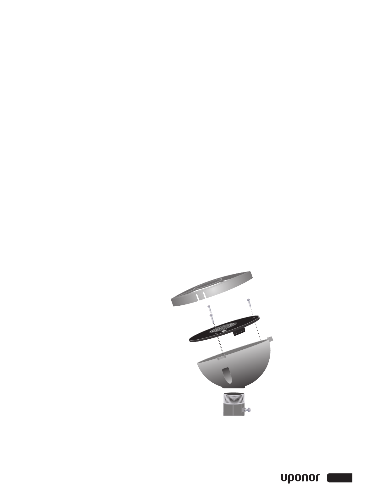
8. Assembly
a. Align the blue sensor disk
Uponor logo with the highest
point of the sensor enclosure
body. The blue sensor disk has a
notch that ensures the sensor is
installed in the correct position.
b. Insert the three screws into the
holes and screw them until tight.
Do not over tighten.
c. Align the three notches of the
outer ring with the sensor
body and push down until
each of the three corners have
snapped on tight.
YEL
BLU
RED
BLK
Designed &
Assembled in Canada
Jun 2014
Lot 123456
1054-0 3
Aerial Snow Sensor
A3040095
4www.uponorpro.com

Maintenance
The sensor is installed in a harsh
environment. Accumulation of dirt
on the surface of the sensor may
affect snow detection. The sensor
should be checked on a periodic
basis and, when necessary, cleaned.
1. Remove the outer ring by pulling
up on the three catches.
2. Use a cloth with warm soapy
water to clean any dirt.
3. Rinse with water.
4. Align the three notches of the
outer ring with the sensor
body and push down until
each of the three corners
have snapped on tight.
Testing and Troubleshooting
If the Single-zone Snow Melt
Control shows an error message
describing a sensor failure, perform
the following test procedure:
•The 4-conductor wires at the
sensor should be disconnected
(unplug wiring terminal plug).
•Use a good-quality electrical
testing meter with an ohm scale
range of 0 to 2,000,000 ohms.
Using the ohmmeter and standard
testing practices, measure the
resistance between:
1. The yellow (YEL) and black (BLK)
wiring terminals to measure
a 10 kΩ sensor and use the
Temperature vs. Resistance
Table on the following page
to calculate the approximate
temperature reading. Measure
the surface temperature of the
blue sensor disk and compare
versus the yellow to black
temperature reading.
2. Measure the resistance between
the blue (BLU) and black
(BLK) wiring terminals. When
the sensor surface is clean
and dry, the reading should
be 2,000,000 ohms. When
the sensor surface is wet it
should be between 10,000 and
300,000 ohms.
3. Measure the resistance
between the red (RED) and
black (BLK) wiring terminals.
This reading should be
between 45 to 47 ohms.
If resistance readings are outside
of the normal operating range,
the sensor has failed.
5
Aerial Snow Sensor Installation Guide

Temperature Resistance
°F °C
-50 -46 490,813
-45 -43 405,710
-40 -40 336,606
-35 -37 280,279
-30 -34 234,196
-25 -32 196,358
-20 -29 165,180
-15 -26 139,402
-10 -23 118,018
-5 -21 100,221
0 -18 85,362
5 -15 72,918
10 -12 62,465
15 -9 53,658
20 -7 46,218
25 -4 39,913
30 -1 34,558
35 2 29,996
40 4 26,099
45 7 22,763
50 10 19,900
55 13 17,436
60 16 15,311
65 18 13,474
70 21 11,883
75 24 10,501
80 27 9,299
85 29 8,250
Temperature Resistance
°F °C
90 32 7,334
95 35 6,532
100 38 5,828
105 41 5,210
110 43 4,665
115 46 4,184
120 49 3,760
125 52 3,383
130 54 3,050
135 57 2,754
140 60 2,490
145 63 2,255
150 66 2,045
155 68 1,857
160 71 1,689
165 74 1,538
170 77 1,403
175 79 1,281
180 82 1,172
185 85 1,073
190 88 983
195 91 903
200 93 829
205 96 763
210 99 703
215 102 648
220 104 598
225 107 553
Temperature vs. Resistance Table
6www.uponorpro.com

Technical Data
Packaged weight 0.4 lbs (180 g)
Dimensions 1
15⁄16" H x 3
5⁄32" O.D. (50 H x 80 O.D. mm)
Enclosure White PVC plastic, UV stable, NEMA type 1
Operating range -40 to 122°F (-40 to 50°C)
Compatible equipment Uponor Single-zone Snow Melt Control (A3040654)
7
Aerial Snow Sensor Installation Guide

SnMlt_AerialSnowSensor_InsG_H501_1114, Copyright © 2014 Uponor. Printed in the United States. MKT10049_AA
Uponor, Inc.
5925 148th Street West
Apple Valley, MN 55124 USA
Tel: 800.321.4739
Fax: 952.891.2008
Uponor Ltd.
2000 Argentia Rd., Plaza 1, Ste. 200
Mississauga, ON L5N 1W1 CANADA
Tel: 888.994.7726
Fax: 800.638.9517 www.uponorpro.com
Table of contents
Other Uponor Accessories manuals