Section 4
Tool Operation and Guidelines
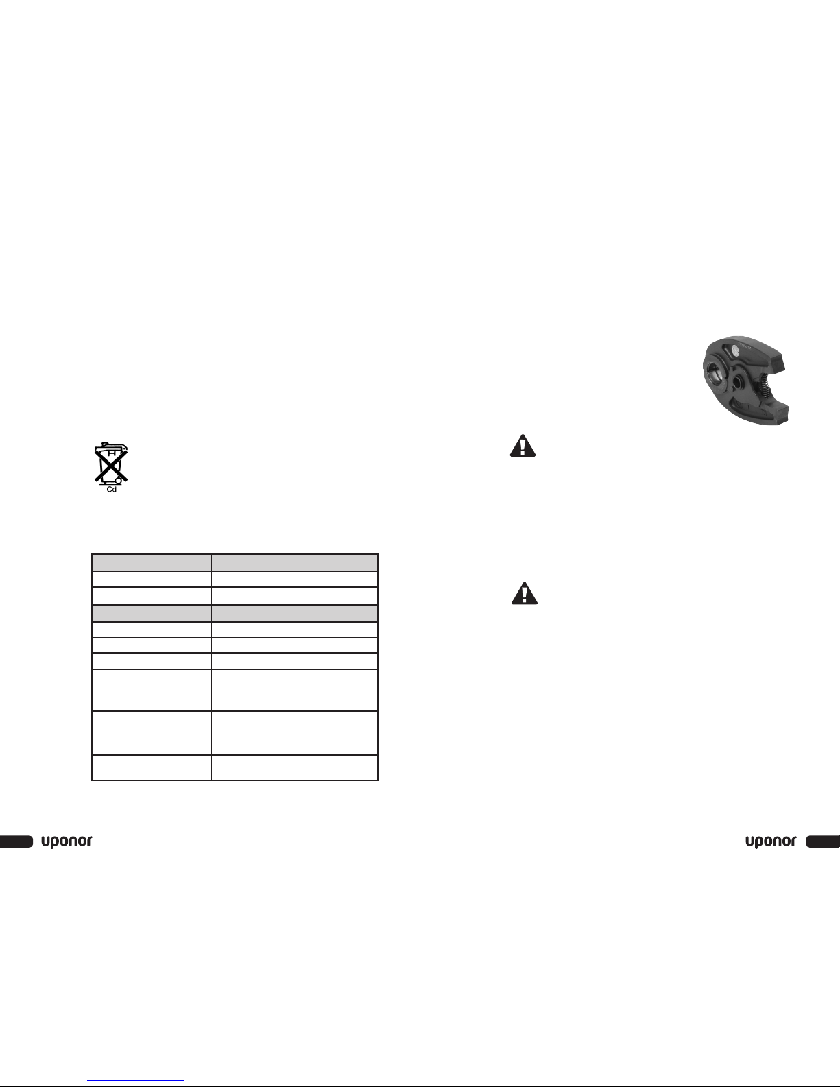
Installing and Changing Press Jaws
Refer to the following instructions to properly
install and change press jaws.
Note: Use only Uponor Mini-Press Battery Tool
Press Jaws on the Mini-Press Battery Tool. Using any
other jaws will void the warranty.
Warning: Prior tochanging the jaws, remove the battery to make
sure the tool doesn’t turn on.
1. Select the proper size press jaw for the application.
Note: Prior to installing the press jaws, check the head and jaws for
damage or excessive wear. Never use a damaged tool or jaws.
2. Disengage the locking pin by simultaneously pushing it in and turning
it counterclockwise.
3. The spring-loaded pin will pop out of its holder.
4. Insert the appropriate press jaw into the head, and push the locking pin
back into its proper position.
Warning: Ensure the locking pin is securely in place. Failure to
do so can cause personal injury or damage to the tool.
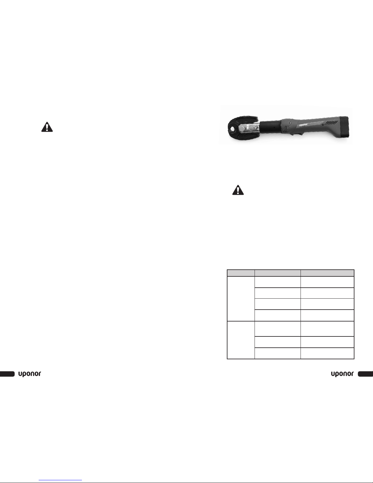
Tool Operation
Refer to the following instructions tooperatethe Mini-Press Battery Tool.
1. Beforeusing the Mini-Press Battery Tool, always perform a test
connection. Ensure the tips of the jaws close completely after
completing the connection. If the jaws do not close properly, refer
to the Troubleshooting section on page 9 for information.
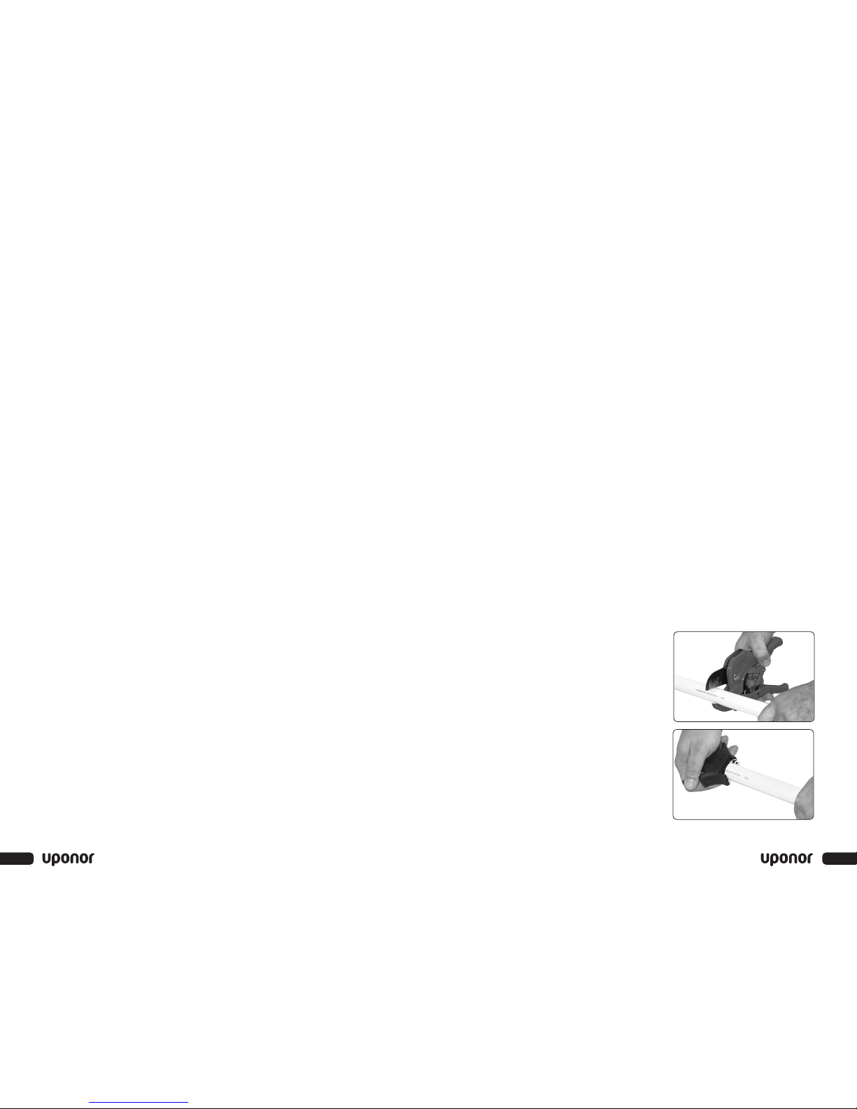
2. After mounting the fitting on the tubing, open the jaws by manually
compressing them at the base near the tool body.
3. Position the jaw on the fitting.
4. Actuate the trigger to start the pressing cycle.
5. Continue holding the trigger until the pressing cycle is complete
(visually check toensure the tips of the jaws are completely closed).
6. Once the pressing cycle is complete, release the trigger.
7
Section 4 – Tool Operation and Guidelines
• Do not allow metal objects (e.g., screws, cutlery, nails) to come in
contact with the battery contacts.
• Use only the provided charger to charge the batteries. Using any other
charger will void the warranty.
• Use only the batteries provided. Using any other battery will void
the warranty.
• Use Uponor-recommended charging procedures. Incorrect use leads
to short circuits, overheating or battery fluid leakage.
• To prolong the battery’s life, avoid overcharging. Do not charge for
more than two days.
• Replace the battery if there is a substantially reduced operating time
after proper charging.
• This symbol, located on the underside of the battery pack,
signifies the battery needs to be disposed of properly in
accordance with local environmental regulations. Do not
incinerate the battery or dispose of the battery in common
waste-removal containers.
Charging Indicators
Two LEDs signal the charger’s status. Refer to Table 3-1 for the
LED definitions.
Table 3-1: LED Definitions
6
www.uponor-usa.com
Left LED (Opposite + Pole) Definition
Solid Red Charger has power and is ready for operation.
Flashing Red Charger is defective.
Right LED (Below + Pole) Definition
Solid Green Batteryis charging.
Solid Yellow Battery is 90% charged.
Flashing Green Battery is completely charged.
Flashing Red and Green Charging stopped due to an extreme
temperature condition.
Solid Red Battery is defective.
Flashing Red Battery is too hot or too cold. Remove
the battery immediately and wait for
battery temperature to reach between
50 and 104°F (10 to 40°C).
LED Off Batterypolarity is reversed or the battery
circuit is open.