Upright MB20N Guide

S
E
R
VI
C
E
&
P
A
R
T
S
M
A
NU
A
L
POWERED ACCESS
WORK PLATFORM
MB20
N
/26


FOREWORD
This manual is divided into six main sections.
SECTION 1 INTRODUCTION
General description, including machine specifications and limitations.
SECTION 2 OPERATION AND SPECIFICATIONS
Information on how to operate the work platform and how to prepare it for operation.
SECTION 3 MAINTENANCE
Preventative maintenance and service information.
SECTION 4 TROUBLESHOOTING
Causes and solutions to typical problems.
SECTION 5 SCHEMATICS
Schematics and valve block diagram with description and location of components.
Large schematic drawings may be located in the pocket at back of the manual.
SECTION 6 ILLUSTRATED PARTS BREAKDOWN
Complete parts lists with illustrations.
Large parts drawings may be located in the back of the manual.
MB20N/26 SEVICE AND PARTS MANUAL
PART NUMBER: 501376-001
SERIAL NO. MB20N0132 - current
MB26 0245 - current

1.
Introduction
1 - 1
Section 1
1.
Introduction
1.1 I
NTRODUCTION
P
URPOSE
& L
IMITATIONS
This Service & Parts Manual is designed to provide instructions and illustrations for the
safe operation and maintenance of the MB20N & MB26 Work Platform manufactured by
Upright Powered Access Ltd. The purpose of this machine is to provide fast and safe
access to difficult to reach areas. The machine may only safely operated on firm level
ground. Refer to the Specification section for the machines access limitations.
DO NOT use on soft ground or on slopes greater than 2 degrees.
DO NOT use the lifting mechanism to raise or lower goods or persons except within the
cage and subject to the weight limitations.
DO NOT enter the platform from a structure, rack or other platform.
S
COPE
This manual includes the procedures and responsibilities for the inspection,
transportation, safe operation, maintenance, and repair of this product. The
Maintenance Section within the Parts & Service Manual also covers preventative
maintenance and troubleshooting.
S
PECIAL
I
NFORMATION
Throughout this manual the users attention is drawn to these special warning boxes:
1.2 G
ENERAL
D
ESCRIPTION
The MB20/26 are self propelled, fast acting aerial work platforms, designed to raise two
operators with hand tools to a platform floor height of 6.00 m and 7.76 m respectively.
The accessible height is approximately 2.00 m above these figures. It is designed to
travel with safe working load and work tools up to an upper limit of 215 kg (475 lbs). The
unit offers the ability to reach over obstacles but must be used on firm and level ground
at all times.
DANGER
! !
Indicates an imminently hazardous situation which, if not avoided, will
result in severe injury or death.
WARNING
!!
Indicates a potentially hazardous situation which, if not avoided,
could result in severe injury or death.
CAUTION
!!
Indicates a potentially hazardous situation which, if not avoided, may
result in minor or moderate injury.

1.
Introduction
1 - 2
P
LATFORM
The MB20/26 platform is large enough for two operators and has a free-draining
perforated floor with 150 mm toeboards. Hand-rails are constructed from aluminium
tubing and a safety drop-bar is provided at the entrance. Safety harness anchor points
are also fitted in the floor of the platform. These must be used at all times. The main
controls are fitted to this platform.
P
LATFORM
C
ONTROLLER
The primary (Upper) control box is permanently fitted to the front of the platform. It
features a joystick which provides proportional control for raising or lowering the mast,
raising or lowering the jib or rotating the complete mast assembly. The same joystick is
also used to drive and steer the machine.
A safety Interlock Switch or ‘deadman button’ is incorporated into the Joystick. It must
be activated at all times in order to operate any function. This feature allows for one-
handed operation. A comprehensive explanation of control functions is given in the
Operators Manual - a copy of which shall be located in the platform document wallet
located just beneath the upper control station in the platform.
The secondary (Lower) control box is fitted to the mast cover at arm level. It features a
‘deadman’ enable button and selector buttons to provide pre-programmed speeds for
all functions except drive and steering. This control station is used primarily for service-
type operations including pre-operation inspection. It should never be used to position
a manned or unmanned platform. It may be used in the event of emergency, however,
to lower the manned platform.
E
LEVATING
A
SSEMBLY
The platform is raised and lowered by a combination of a steel jib and a series of
telescoping mast sections. The main hydraulic cylinder, mounted within the masts, lifts
the first mast directly. The other masts are connected by a system of heavy duty plate
chains and pulleys to ensure sequential lifting.
A parallel system of heavy duty straps ensures that the masts descend in the proper
sequence and also ensure that a mast cannot be held in suspension by an obstacle
during descent.
The jib cylinder provides a lifting arc to the jib and cage assembly. All hydraulic
functions are carried out using solenoid operated control valves. Each cylinder features
an integral holding valve to prevent uncontrolled descent in the case of a hose bursting.
WARNING
!!
DO NOT use the work platform without guardrails properly
assembled and in place.
WARNING
!!
NEVER operate the machine from the upper controls until the
platform entrance drop-bar is in the fully lowered position and the
safety harness is fitted.

1.
Introduction
1 - 3
R
OTATION
G
EAR
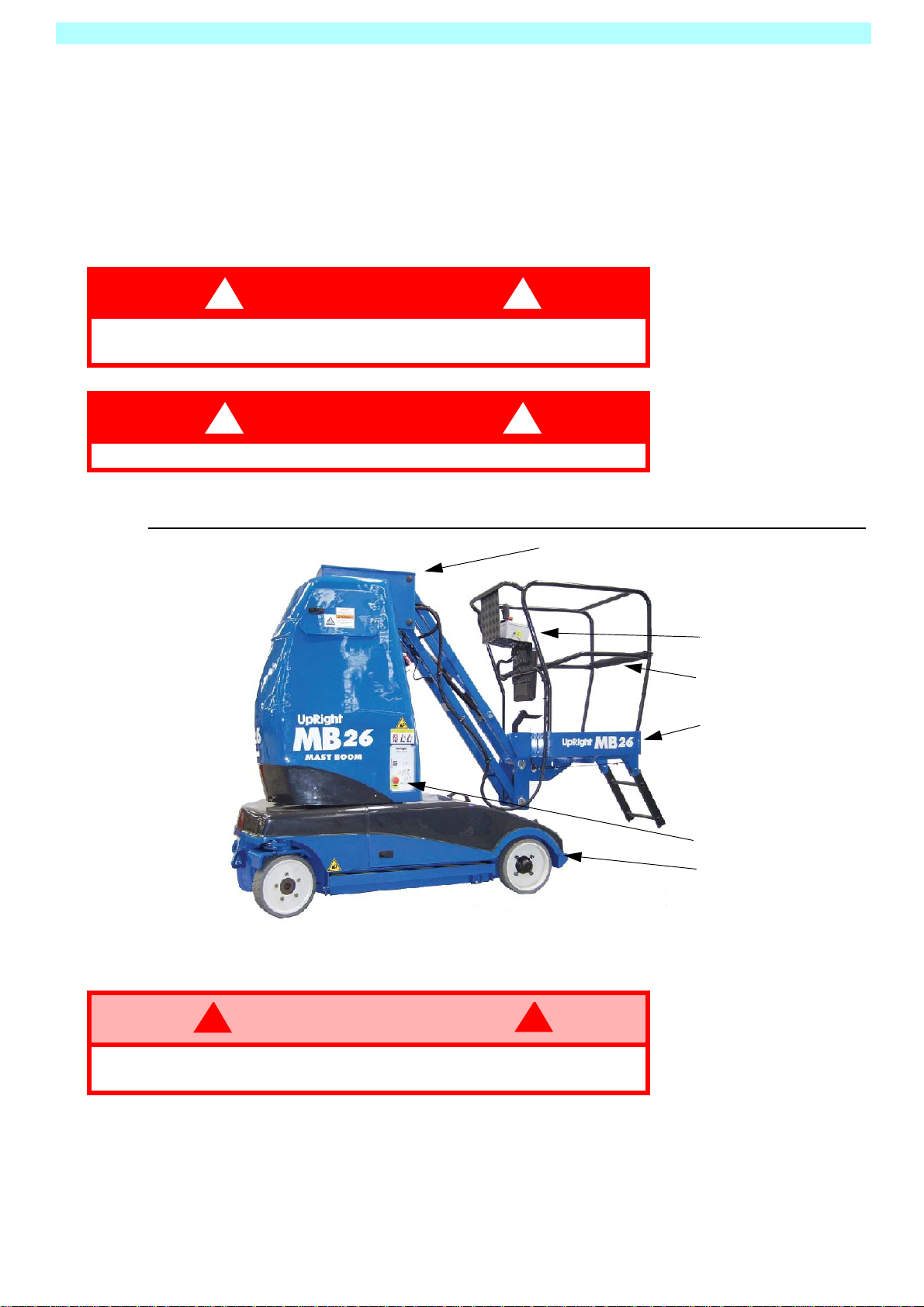
The complete mast, jib and cage assembly can be rotated to provide a maximum
outreach of 2.6m in the case of the MB20 and 2.96m in the case of the MB26 machine.
This dimension is measured from the centreline of rotation and is carried out by means
of an integral hydraulic motor driving a Worm Drive Unit, around a Slew Gear.
D
RIVE
& S
TEER
S
YSTEM
An electronic controller, mounted in the chassis, is pre-programmed to adjust the upper
speed limit of each individual function. The controller limits the rotational speed of the
electronic motor and oil pump, thereby limiting the maximum oil flow rate.
The following functions are controlled and driven by the electro-hydraulic system:
•Traction Drives (Fwd & Rev) mast stowed/mast raised.
•Steering and Jib elevation.
•Mast elevation, descent and rotation.
•The Jib descent function is gravity operated and is determined by built in flow
regulators.
P
OWER
S
YSTEM
The Power System (Prime Mover) incorporates four 6V batteries driving a 4KW electro-
hydraulic pump. The pump drives all hydraulic cylinders and the traction drive motors. A
single multi-valve control block diverts the oil pressure to the individual actuators. The
oil flow rate is limited by the pre-programmed speed setting on the motor but is
determined by the position of the joystick in the Upper Control Box.
1.3
W
ORKSHOP
P
ROCEDURES
All information contained in this manual is based on the latest product information
available at the time of printing. We reserve the right to make changes at any time
without notice.
No part of this publication may be reproduced, stored in retrieval system, or transmitted,
in any form by any means, electronic, mechanical, photocopying, recording, or
otherwise, without the prior written permission of the publisher. This includes text,
figures, and tables.
CAUTION
!!
Detailed descriptions of standard workshop procedures, safety
principles and service operations are not included. Note that this
manual does contain warnings and cautions against some specific
service methods that could cause personal injury, or could damage
a machine or make it unsafe.
Please understand that these warnings cannot cover all
conceivable ways in which service, whether or not recommended
by UpRight, might be done, or of the possible hazardous
consequences of each conceivable way, nor could UpRight
investigate all such ways.
Anyone using service procedures or tools, whether or not
recommended by UpRight must satisfy themselves thoroughly that
neither personal safety nor machine safety will be jeopardized.
When in doubt, contact your local distributor or UpRight.

2 - 1
2. Operation & Specifications
2.1 I
NTRODUCTION
S
PECIAL
L
IMITATIONS
The purpose of this machine is to provide fast and safe access to difficult to reach
areas.
Refer to the Specification section for the machines access limitations.
Travel with the platform raised is limited to creep speed range.
M
ANUAL
F
ORCE
Manual force is the force applied by the occupants to objects such as walls or other
structures outside the work platform.The maximum allowable manual force is limited to
200 N (45 lbs.) of force per occupant, with a maximum of 400 N (90 lbs.)
P
LATFORM
C
APACITY
The Platform is designed to travel with safe working load (SWL) including work tools to
an upper limit of 215 kg (475 lbs).
B
EAUFORT
S
CALE
Never operate the machine when wind speeds exceed 12.5m/s (28 m.p.h.)
[Beaufort scale 6].
DANGER
! !
DO NOT exceed the maximum manual force.
NEVER exceed the platform capacity.
B
EAUFORT
R
ATING
W
IND
S
PEED
G
ROUND
C
ONDITIONS
M
/
SKM
/
HFT
./
S M
.
P
.
H
.
3 3,4~5,4 12,25~19,4 11.5~17.75 7.5~12.0 Papers and thin branches move.
Flags wave.
4 5,4~8,0 19,4~28,8 17.75~26.25 12.0~18 Dust is raised, paper whirls up, and small branches
sway.
5 8,0~10,8 28,8~38,9 26.25~35.5 18~24.25 Shrubs with leaves start swaying.
Wave crests are apparent in ponds or swamps.
6 10,8~13,9 38,9~50,0 35.5~45.5 24.5~31 Tree branches move.
Power lines whistle. It is difficult to open an umbrella.
7 13,9~17,2 50,0~61,9 45.5~56.5 31.~38.5 Whole trees sway.
It is difficult to walk against the wind.
DANGER
! !
DO NOT use on soft ground or on slopes greater than 2 degrees.
The work platform is NOT intended for use on uneven or rough
terrain.
ONLY operate this machine on FIRM and LEVEL ground.

2 - 2
2. Operation & Specifications
2.2 G
ENERAL
D
ESCRIPTION
The MB20/26 are self propelled, fast acting aerial work platforms, designed to raise
two operators with hand tools to a platform floor height of 6.00m and 7.76m
respectively. The accessible height is approximately 2.00m above these figures.
The unit offers the ability to reach over obstacles but must be used on firm and level
ground at all times.
Figure 3: Work Platform
DANGER
! !
DO NOT use the lifting mechanism to raise or lower goods or persons
except within the cage and subject to the specified weight limitations.
DANGER
! !
DO NOT enter the platform from any structure, rack or other platform.
Platform
Platform Controller
Elevating Assembly
Chassis Controls
Chassis
Safety Drop-bar
WARNING
!!
DO NOT use the work platform without safety drop-bar in place and
with the safety harness fitted.

2 - 3
2. Operation & Specifications
2.3 S
AFETY
I
NSPECTION
This Safety Inspection shall be carried out by the owner immediately prior to
transporting this machine.
This Safety Inspection shall also be carried out by the user prior to use each day.
The procedure is to carry out the following 14 checks in order as follows.
1. Remove the rear chassis covers by means of the two top twist-locks and the two lift-
and-turn catches at the sides. The cover is removed by sliding it backwards and
upwards. Use the central handle provided.
2. Ensure that the mast and jib are fully lowered. Remove the hydraulic oil filler cap and
check that the hydraulic oil level is correct. Oil should be visible on the dip stick. Top up
as necessary using hydraulic oil Viscosity Grade ISO 46.
3. Inspect the chassis area for oil leaks, loose parts, frayed cables and hoses and
structural damage etc. Check that all cable connections to the solenoid valves are
intact.
4. Open the Inspection hatches on both sides of the upper mast cover. Check that the AC
mains cable is disconnected from the battery charger. Check the electrolyte level in
each battery cell. Top up as necessary with distilled water only.
5. Use the automated battery top-up system fill the batteries to the correct electrolyte
level. This is done by opening the shut off valve and pressing the green fill button for
approximately 10 seconds, then re-closing the shut-off valve.
Batteries should be examined for cracks, acid leakage and terminal corrosion. Take
corrective action immediately if either check fails.
Figure 3: Battery Fill Button & Valve
Battery fill Button
Shut off Valve
In CLOSED Position
CAUTION
!!
Vehicles fitted with the automated battery top-up system with shut
off valve, top up the battery cells with distilled water using the
electrolyte fill button, ensuring that the shut-off valve is open during
the fill and closed after use.
This is the only time this valve should be opened.

2 - 4
2. Operation & Specifications
Figure 4: Lower Control Panel
6. Prior to operating the functions, check that the upper and lower emergency stop
buttons on each control station are retracted; turn clockwise if necessary. Carry out
the following function from the Lower Control Station.
NOTE: DO NOT enter the platform at this stage.
7. Check jib operation by extending the jib to its fully elevated position. Check for
correct routing of the hoses and cables. Check the Emergency Lowering feature of
the jib. Ensure that when the Emergency Lowering lever/button is disengaged, the jib
no longer descends. Return the jib to its rest position using the normal Lower Control
Station.
8. Check mast chains by elevating the masts approximately 30cm above the rest
position. Check for correct routing of the energy chain. Raise the masts to full height
and check for correct adjustment of each lifting chain as follows. Each chain in the
pair should bear load. Use a hand held spring balance or tensiometer apply a
nominal load (approximately 10kgf.) to either chain in the pair. Apply the load about
half way up the chain. Record the approximate deflection i.e. the offset distance from
the mast. Repeat the measurement on the adjacent chain at the same location.
Chains bearing equal load will deflect equal amounts. Carefully adjust the slack chain
until the deflections are approximately equal. Torque up the locknuts to 70 Nm.
NOTE: Apply a thin layer of grease to the lifting chains with a small paintbrush.
1. Enable Button
2. Analog Rocker
3. Mast Button
4. Jib Button
5. Rotate Button
6. Emergency Stop
1
3
5
2
4
6
CAUTION
!!
Over-tensioning of either lifting chain will result in unnecessary
lifting of the mast.
This will lead to a subsequent increase in machine stowed height.

2 - 5
2. Operation & Specifications
The function of the mast straps is to ensure that masts descend in the correct order
and more importantly, that masts cannot continue to descend if the jib or platform
meets an external obstacle. Raise the masts about 30cm. Check the external mast
clamp screws for tightness. Pull on the short length of each strap and check that they
are secure. Refer to the maintenance manual for instructions on more stringent
periodic checks on these straps.
Check the Emergency Lowering feature of the mast. The lever is located in the upper
mast over. Open the left hand battery inspection hatch and locate the ‘Emergency
Lowering’ decal label. Check the wear pads for damage or heavy scoring. Replace as
necessary.
9. Elevate the jib fully. Using the Lower Control Station, turn the mast assembly through
about 90 degrees. Check the correct routing of the hoses and cables and the correct
smooth operation of the energy chain in its chassis base slide. Continue rotating
through 180 degrees in both directions. Confirm that the rotation stops are intact.
10.STANDARD PLATFORM CONTROLS Repeat the mast, jib and rotate functions from
the Upper Control Station in the platform. Check that pressing the emergency stop
button prevents subsequent operation of the joystick.
11. EMERGENCY OVER-RIDE While in the platform, ask a colleague to deflect the tilt
alarm sensor body. This sensor is located on the chassis base. The alarm will sound
and all normal function will become interrupted.
Figure 5: Joystick and Tilt Sensor
12.MACHINE TRAVEL - UNELEVATED Travel functions are possible only from the
platform Upper Control Station. As with all such controls, the deadman handgrip switch
must be depressed before any function can operate.
Select Drive on the upper control panel. Pushing back and forward on the joystick
moves the machine backwards and forwards respectively.
The pothole protection will begin to retract immediately. However, full demand speed
will not be realised until the bars are fully raised. This takes about 3 seconds. Check
that the motion alarm DOES sound during travel. Check that the thumb operated
switches on the top of the joystick operates the front wheel steering.
13.MACHINE TRAVEL-ELEVATED While the masts are raised, it is possible to drive and
steer the machine at a much reduced speed. Also note that while the masts are raised,
the pothole protection bars should be fully extended and should remain extended
during slow speed motion of the machine.
Tilt Sensor
Joystick
with Deadman Grip

2 - 6
2. Operation & Specifications
14.FINAL PREPARATION Configure the masts and jib to the stowed position. Replace
all machine covers and secure.
NOTE: The machine is now ready for Operation or Transportation.
2.4 O
PERATION
OF
THE
P
LATFORM
C
ONTROLS
The primary (Upper) control box is permanently fitted to the front of the platform. It
features a multi-use joystick which provides proportional control for all the machines
functions. That includes, raising or lowering the mast, raising or lowering the jib,
rotating the mast assembly, and also to drive and steer the machine.
A safety Interlock Switch or ‘deadman button’ is incorporated into the Joystick. It
must be activated at all times in order to operate any function. This feature allows for
one-handed operation.
The secondary (Lower) control box is fitted to the mast cover at arm level. It features
an enable button and selector buttons to provide pre-programmed speeds for all
functions except drive and steering. This control station is used primarily for service-
type operations including pre-operation inspection. It should never be used to
position a manned or un-maned platform.
NOTE: It may be used in the event of emergency to lower the manned platform.
C
ONTROLS
AND
I
NDICATORS
The pre-operation safety checks should be carried out prior to operation. These
checks are detailed in the previous section. Operators who follow these guidelines
will become familiar with the controls and indicators on the machine.
This section summarises the controls and indicators in tabular form and provides
more detailed information.
WARNING
!!
The issue of reduced speed while elevated and deployment of the
pothole protection bars is crucial to the safe operation of this
machine.
The machine may not be released or operated unless these
functions operate properly.
WARNING
!!
NEVER operate the machine from the upper controls until the
platform entrance drop-bar is in the fully lowered position and the
safety harness is fitted.

2 - 7
2. Operation & Specifications
U
PPER
C
ONTROL
P
ANEL
Figure 3: Upper Control Panel
C
ONTROL
F
UNCTIONS
WARNING
!!
DO NOT operate the machine from the upper controls until the
platform entrance drop-bar is in the fully lowered position and your
safety harness has been fitted and attached.
1.Joystick (forward/back)
2.Deadman Grip
3.Emergency Stop
4.Steering Switch (L/R)
5.Jib Select Button
6.Mast Select Button
7.Rotate Select Button
8.Drive (Slow)
9.Drive (Fast)
10.Key Switch
11. Horn 12. Multi-Function
Display
I
TEMS
N
AMES
F
UNCTION
1Joystick
Refer to the decal logic diagrams for correct direction of
motion.
e.g. If Drive is preselected - pushing forward moves
machine forward.
2 Deadman Grip The ‘Deadman’ grip switch on the joystick must be
grasped for any function to operate.
3 Emergency Stop Push this red button at any time to isolate power.
Turn clockwise to reset.
Table 1: Platform Controls and Indicators

2 - 8
2. Operation & Specifications
L
OWER
C
ONTROL
P
ANEL
4 Steering Switch Turns the wheels left or right.
5 Jib Select Button Pre-selects the Jib function.
6 Mast Select Button Pre-selects the Mast function.
7 Rotate Select Button Per-selects the Mast Rotate function.
8 Drive (Mast Raised) Pre-selects the drive function with the mast in the raised
position and for high torque. (i.e. slow speed)
9 Drive (Mast Lowered) Pre-selects the drive function with the mast in the lowered
position. (i.e. maximum speed)
10 Key Switch Activates (ON) and De-actives (OFF) all machine
functions.
11 Horn Button Use to warn bystanders or to attract attention.
12 Multi-Function Display Displays the Percentage battery life. (99=Full, 01-Empty)
I
TEMS
N
AMES
F
UNCTION
Table 1: Platform Controls and Indicators
I
TEMS
N
AMES
F
UNCTION
1 Enable Button This button enables the Rocker Switch, and must be
held down during operation
2 Rocker Switch Activates the pre-selected operation, in either direction
3 Mast Select Button Pre-selects the Mast function.
4 Jib Select Button Pre-selects the Jib function.
5 Rotate Select Button Per-selects the Mast Rotate function.
6EmergencyStop
Push this red button at any time to isolate power.
Turn clockwise to reset.
Table 2: Chassis Controls and Indicators

2 - 9
2. Operation & Specifications
Figure 4: Lower Control Panel
T
YPICAL
O
PERATION
Raising the mast.
• The Keyswitch located on the Upper Control box must be turned on.
• Select Mast by pressing the Mast button (3)
• Press and hold the enable button (1),
• Activate the Rocker Switch (2) in the direction required.
E
LEVATING
& L
OWERING
THE
W
ORK
P
LATFORM
Before operating the MB20 Work Platform it is imperative that the pre-operation Safety
Inspection has been completed and any deficiencies have been corrected. The
operator must also be fully trained in the use of this machine.
Before beginning any operation, the following checks should be carried out.
NOTE: Chassis controls are for service use only.
1. Enable button
2. Rocker switch
3. Mast selection button
4. Jib selection button
5. Rotate selection button
6. Emergency Stop
1
3
5
2
4
6
WARNING
!!
ENSURE that no other persons are within 1 metre of the machine.
Be aware of the pothole protection bar hazard on both sides of the
machine.
LOOK up and around for obstructions before performing the lift or
drive functions.
DO NOT overload the platform.
DO NOT operate within 3 metres of any electrical power cables.
THIS WORK PLATFORM IS NOT ELECTRICALLY INSULATED.

2 - 10
2. Operation & Specifications
1. Enter the Platform through the entrance at the rear of the MB20/26 and ensure that
the drop bar is in position. Raise and lock the entry step by means of the pedal in the
platform.
2. Before using the machine all local Safety Regulations involving helmets and
restraining devices should be observed. Safety harness lanyards, not exceeding 1
metre in length, should be attached to anchor points in cage floor.
3. Ensure that the ‘ON/OFF Key Switch on the Upper Control Box is turned to the ‘ON’
position and both emergency stop buttons are off (twist clockwise if necessary).
4. Check the Display L.E.D. is illuminated. If not, the battery may need recharging.
5. Check if the audible alarm sounds due to un-level ground. None of the functions can
work if the machine is not level.
T
RAVEL
WITH
W
ORK
P
LATFORM
L
OWERED
Refer to Tables 1 & 2 for controls and indicators.
1. Verify that both Lower and Upper Control Console Emergency Stop Button is in the
‘ON’ position (turn clockwise to reset).
2. Climb into the Platform and check that the Keyswitch is turned to the ‘ON’ position
and that the Drive Button is illuminated. Ensure that the drop bar is in position.
3. Check that the route is clear of persons, obstructions, pot holes or ledges and is
capable of supporting the wheel loads. Also, check that the clearances above, below,
and to the side of the Work Platform are sufficient.
4. To steer the MB20/26, activate the Deadman Switch while pushing the Steering
Thumb-switch, on top of the Joystick, LEFT or RIGHT to turn the wheels. Observe
the tyres while manoeuvring to ensure correct direction.
NOTE: Steering is not self-centring. The wheels must be returned to the straight ahead
position by operating the Steering Switch.
T
RAVEL
WITH
W
ORK
P
LATFORM
E
LEVATED
Refer to Tables 1 & 2 for controls and indicators.
NOTE: The Work Platform will travel at reduced speed when in the elevated position.
1. Check that the route is clear of persons, obstructions, pot holes or ledges and is
capable of supporting the wheel loads. Also, check that the clearances above, below
and to the side of the Work Platform are sufficient.
2. Ensure that the pothole guards remain in the extended (down) position during
elevated travel.
CAUTION
!!
If the machine stops driving and the Tilt Alarm sounds, lower the
Platform immediately.
Using the Emergency Override functions, move the machine to a
level location before re-elevating the platform.
Travel with platform elevated ONLY on firm and level surfaces.

2 - 11
2. Operation & Specifications
E
MERGENCY
S
ITUATIONS
In any emergency situation, the immediate action is to push the red “Emergency Stop”
button. This will instantly cut of all electrical power to the controls. The button must be
twisted in a clockwise direction in order to recommence control.
However, the switch should be reset only when it is safe to do so.
If the Audible warning alarm sounds, normal control functions will cease to operate.
This will be due to the following problem;
• The Tilt Sensor has been activated
NOTE: that during emergency operation, controls will operate only at a fixed, slow speed
and will not allow the raising of the Booms. The Booms can only be lowered.
E
MERGENCY
L
OWERING
(
BY
HAND
)
Should the machine become inoperable when elevated request a person on the
ground to lower the platform using the emergency lowering valves. Lower the mast
structure before lowering the jib/platform structure.
NOTE:Lower the masts fully before lowering the jib structure.
Figure 5: Emergency Lowering - Mast Valve
Figure 6: Emergency Lowering - Jib Valve
M
ANUAL
R
OTATION
1. Lower the masts and jib fully before manually slewing the assembly. Press the
Emergency Stop Button to prevent inadvertent powered motion.
2. Locate the opening behind the front right drive wheel. Apply a 7/8 inch socket wrench
with extension bar to the shaft and turn to rotate the elevating assembly. (Turning the
wheel fully to one side will facilitate this operation).
CAUTION
!!
During manual emergency lowering, extreme care must be taken
to ensure that the person carrying out the task is not struck by the
jib or platform structure.
Locate the red lever behind the
mast cover inspection door on the
left hand side of the machine. By
pushing the lever up, the mast will
descend fully under gravity.
Releasing the spring-loaded lever
will cease this operation
immediately if required.
The Jib may be manually lowered
by operating the manual release
valve located between the Jib
Structure.

2 - 12
2. Operation & Specifications
2.5 T
RANSPORTATION
M
ACHINE
W
EIGHTS
Before transporting or lifting the MB20N/26 machine be aware of its weight. It is very
important to realise that the centre of gravity of the stowed machine is approximately
80 cm above ground and in the plane of the energy chain which is located on the
back of the mast.
MB20N CE Version= 2550 kg
MB20N US Version= 3000 kg (6615 lbs)
MB26 CE Version = 2650 kg
MB26 US Version = 3150 kg (6945 lbs)
In cases of particular difficulties with lifting or shipping it is possible to remove the
single block ballast from the machine. Remove the 13 screws connecting the ballast
cover to the mast. Undo the 4 bolts connecting the ballast to the mast and use a
forklift to remove the ballast block. The ballast block weighs 850 kg on the CE version
and 1300kg on the US (ANSI) version.
L
IFTING
BY
F
ORK
-L
IFT
Figure 3: Lifting by Forklift
WARNING
!!
This work must not be carried out without the prior written permission
of UpRight Powered Access.
DANGER
! !
Forklifting is for transport only. See machine weights and ensure that
the forklift is of adequate capacity.
Front
800mm
Adjust the forks so that
the minimum clearance
between them is 800mm
as shown.
Approach the machine
from either side but place
the fork as close as
possible to the front wheel
as shown.

2 - 13
2. Operation & Specifications
1. Never approach the MB20 from the front or rear while fork lifting.
2. Use maximum forklift tilt as soon as possible when raising the MB20/26.
3. If travelling over sloped or uneven ground it is strongly recommended to temporarily tie
the MB20 jib mount structure to the forklift mast as a safety precaution.
4. The MB20/26 may be lifted by forklift subject to the following strict procedure.
5. Ensure that the mast and jib are fully stowed and that the pothole bars are fully
retracted (raised).
L
IFTING
B
Y
C
RANE
The MB20/26 may be lifted by an overhead hoist/crane subject to the following strict
procedure.
Raise the jib to clear the lifting straps as shown.
Use 4 separate lifting straps connected to a spreader beam. DO NOT use a lesser
number of threaded straps as these could slip and lead to instability. The
recommended minimum capacity of EACH of the 4 straps is 2 tonne and the minimum
length of each strap is 2 metres. Damage to the covers and/or cage rails can occur if a
spreader beam is not deployed during a crane lift.
Figure 4: Lifting by Crane
Apply the straps via 1
tonneshackles toeach
of the 4 lifting lugs on
the chassis.
CAUTION
!!
DO NOT apply lifting straps to any other part of the machine.

2 - 14
2. Operation & Specifications
T
RANSPORT
BY
T
RUCK
The MB20n/26 can be carried on a suitably rated transportation vehicle or trailer.
Because of its high gradeability, the machine can be driven under its own power on to
a standard loading ramp (Up to 14 degrees).
It is recommended to reverse the machine up on to the truck thus forward travelling
down the ramp at the delivery point. Winch-assisted loading is allowable for larger
slopes, however, operate the trucks assist winch at minimum speed to avoid over-
pressurising the hydraulic system in the machine.
When the MB20n/26 is on the truck or trailer it should then be made secure by:-
1. Chocking the wheels.
2. Securing with adequate chains or straps to the lifting lugs on the chassis.
Figure 5: Securing the Platform
T
OWING
& W
INCHING
V
ALVES
The fail-safe brakes are automatically applied when the machine comes to a stop or
in the event of total power loss due to low battery or malfunction of the hydraulic drive
system.
To tow the vehicle or to winch it on to a truck it is necessary to hydraulically bypass
the control valves and release these brakes.
CAUTION
!!
DO NOT loop straps through the cage, ladder or jib as this could
cause permanent structural damage during transportation.
Other manuals for MB20N
1
This manual suits for next models
1
Table of contents
Other Upright Boom Lift manuals
Popular Boom Lift manuals by other brands

Terex
Terex Genie Lift Guard S-40 Operator's manual

Terex
Terex Genie SX-180 Operator's manual

nifty
nifty TM Series Operating and safety instructions

NIFTYLIFT
NIFTYLIFT Heightrider HR28 Series Operating and safety instructions

TEUPEN
TEUPEN LEO 21GT Translation of the original operating instructions

Skyjack
Skyjack SJ45 AJ+ Service manual