Upright AB38 User manual

Operator Manual
This sectionof the Operatormanualis the English languageversion.
Betriebsanleitung
Im zweiten Abschnitt dieserBetriebsanleitung Siedie DeutscheVersion.
ManuelUtilisateur
èLatroisième section de ce manuel est la version en langue Française.
Manual del Usuario
El apartado cuarto de este manual del usuario corresponde a laversión en Españo.
Manuale d’Uso
La quinta sezione di questo manuale d'uso èla versione in lingua Italiana.
(EN) Manualpart number 500423-006 for serial numbers 3700-04243
(DE) Bestellnummer 50 0423-006 ab Seriennumm er 3700 -04243
(FR)Manuel Piècenuméro 500423-006 pour numéro série3700 -04243
(ES) El número de referenciapara el manual es el 500423-006para la
números de seriedel 3700 -04243
(IT) Manuale Ricambi Nume ro 500423-006 per Numeri di Serie da 3700-04243
AB38
Jan 08
WARNING
The AB38N Machine has been re-assessed to ensure
compliance to the Machinery Directive (2006/42/EC).
The Machine rating has been changed from:
2 People Indoors and Outdoors.
To
2 People Indoors and 1 Person Outdoors.
Please attach to the front cover of
your AB38N manual
510327-000


www.upright.com
CAUTION:ONLY TRAINED & AUTHORISED PERSONNEL MAY USE
THIS MACHINE-CONSULT OPERATORS MANUAL BEFORE USE.
THIS PLATFORM IS NOT ELECTRICALLY INSULATED
200kg 2 Persons + 40kg. Equipment
1.1 m/s
400N
MAX. GRADEABILITY 36%
MAX. FORWARD SPEED
MAX. PLATFORM HEIGHT
MAX. PLATFORM LOAD
MAX. LATERAL FORCE
MAX. CHASSIS INCLINATION
CHARGER INPUT VOLTAGE 240V
NOMINAL POWER
58472-008
4kW
BATTERY VOLTAGE
UNLADEN WEIGHT
MAX. WIND SPEED
0°
11.5m
12.5 m/s
48V
3200 kg
UpRight
MODEL AB38W
VIGO CENTRE
TYNE & WEAR, UK.
SERIAL No.
WASHINGTON,
AB38N
MODEL SERIAL No.
BATTERY VOLTAGE
NOMINAL POWER
UNLADEN WEIGHT
MAX. WIND SPEED
CHARGER INPUT VOLTAGE
CAUTION:ONLY TRAINED & AUTHORISED PERSONNEL MAY USE
THIS MACHINE-CONSULT OPERATORS MANUAL BEFORE USE.
THIS PLATFORM IS NOT ELECTRICALLY INSULATED
215kg 2 Persons + 55kg. Equipment
36%
MAX. GRADEABILITY
MAX. FORWARD SPEED 1.1 m/s
MAX. PLATFORM HEIGHT
MAX. PLATFORM LOAD
MAX. LATERAL FORCE
MAX. CHASSIS INCLINATION
400N
0°
11.5m
240V
58472-000
4kW
12.5 m/s
48V
3800 kg
VIGO CENTRE
TYNE & WEAR, UK.
WASHINGTON,
UpRight
18ft 4in
2105psi
CHARGER INPUT VOLTAGE
475 lbs (2 PERSONS + 120 lbs)
THIS PLATFORM IS NOT ELECTRICALLY INSULATED
THIS MACHINE-CONSULT OPERATORS MANUAL BEFORE USE.
CAUTION: ONLY TRAINED & AUTHORISED PERSONNEL MAY USE
THIS MACHINE IS MANUFACTURED TO COMPLY WITH
ANSI A92.5 - 1992
2.5mph
MAX. FORWARD SPEED
MAX. PLATFORM REACH
BATTERY VOLTAGE
MAX. LATERAL FORCE
MAX. HYDRAULIC PRESSURE
MAX. CHASSIS INCLINATION 0°
48V dc
90 lbs
UpRight
MAX. PLATFORM HEIGHT
MAX. PLATFORM LOAD
MODEL AB38N
38 ft
58472-002
5.4 hp
NOMINAL POWER
110/120V
28 mph
MAX. GRADEABILITY
MAX. WIND SPEED
36%
VIGO CENTRE
9057 lbs
SERIAL No.
UNLADEN WEIGHT
TYNE & WEAR, UK.
WASHINGTON,
5.4 hp
NOMINAL POWER
2.5mph
MAX. FORWARD SPEED
THIS PLATFORM IS NOT ELECTRICALLY INSULATED
THIS MACHINE-CONSULT OPERATORS MANUAL BEFORE USE.
CAUTION: ONLY TRAINED & AUTHORISED PERSONNEL MAY USE
THIS MACHINE IS MANUFACTURED TO COMPLY WITH
ANSI A92.5 - 1992
58472-006
CHARGER INPUT VOLTAGE
MAX. GRADEABILITY
MAX. WIND SPEED
UNLADEN WEIGHT
475 lbs (2 PERSONS + 120 lbs)
VIGO CENTRE,
UpRight
BATTERY VOLTAGE
MAX. HYDRAULIC PRESSURE
MAX. CHASSIS INCLINATION
MAX. LATERAL FORCE
MAX. PLATFORM REACH
MAX. PLATFORM HEIGHT
MAX. PLATFORM LOAD
MODEL
90 lbs
18ft 4in
48V dc
0°
2105psi
38 ft
AB38W SERIAL No.
TYNE & WEAR, UK
WASHINGTON,
36%
110/120V
28 mph
7496 lbs
ENGLISH
When contacting UpRight for service or parts information, be sure to include the MODEL and SERIAL NUMBERS from the
equipment nameplate. Should the nameplate be missing, the SERIAL NUMBER is also stamped on top of the chassis
above the front axle pivot.
AB38
Serial Numbers 3700 – Current
Serial number stamped on floor of chassis
beneath the steering cylinder.


Page 1
OPERATION MANUAL
WARNING
All personnel shall carefully read, understand and follow all safety rules and operating
instructions before operating or performing maintenance on any UpRight aerial work platform.
Safety Rules
USE OF THE AERIAL WORK PLATFORM: This aerial work platform is intended to lift persons and his tools as well as the material
used for the job. It is designed for repair and assembly jobs and assignments at overhead workplaces (ceilings, cranes, roof struc-
tures, buildings etc.). All other uses of the aerial work platform are prohibited!
THIS AERIAL WORK PLATFORM IS NOT INSULATED! For this reason it is imperative to keep a safe distance from live parts of
electrical equipment!
Exceeding the specified permissible maximum load is prohibited! See “Platform Capacity” for details.
The use and operation of the aerial work platform as a lifting tool or a crane is prohibited!
NEVER exceed the manual force allowed for this machine. See “Manual Force” for details.
DISTRIBUTE all platform loads evenly on the platform.
NEVER operate the machine without first surveying the work area for surface hazards such as holes, drop-offs, bumps, curbs, or
debris; and avoiding them.
OPERATE machine only on surfaces capable of supporting wheel loads.
NEVER operate the machine when wind speeds exceed this machine’s wind rating. “Beaufort Scale” for details.
IN CASE OF EMERGENCY push EMERGENCY STOP switch to deactivate all powered functions.
IF ALARM SOUNDS while platform is elevated, STOP, carefully lower platform. Move machine to a firm, level surface.
Climbing up the railing of the platform, standing on or stepping from the platform onto buildings, steel or prefab concrete structures,
etc., is prohibited!
Dismantling the entry gate or other railing components is prohibited! Always make certain that the entry gate is closed and securely
locked!
It is prohibited to keep the entry gate in an open position when the platform is raised!
To extend the height or the range by placing of ladders, scaffolds or similar devices on the platform is prohibited!
NEVER perform service on machine while platform is elevated without blocking elevating assembly.
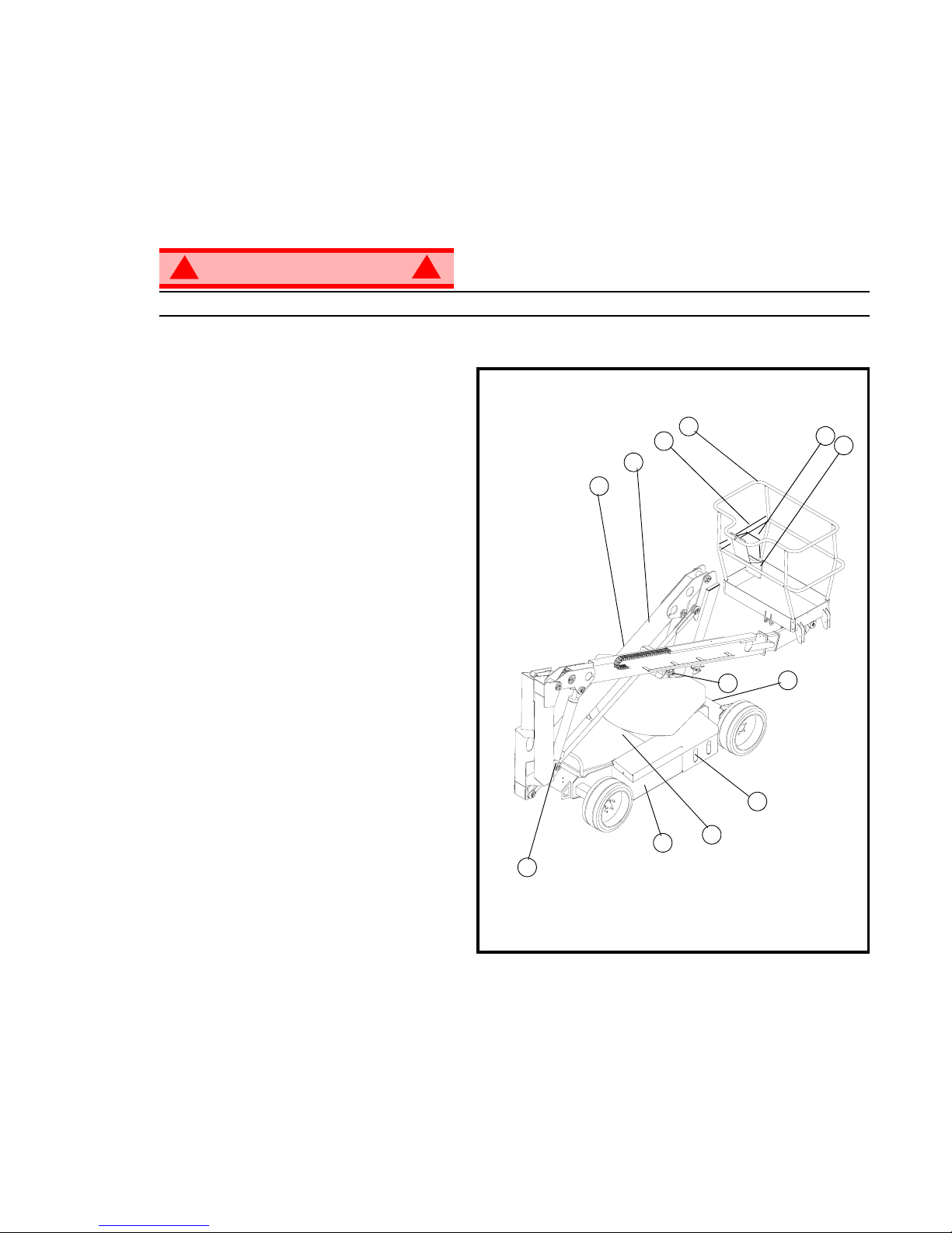
INSPECT the machine thoroughly for cracked welds, loose or missing hardware, hydraulic leaks, loose wire connections, and dam-
aged cables or hoses before using.
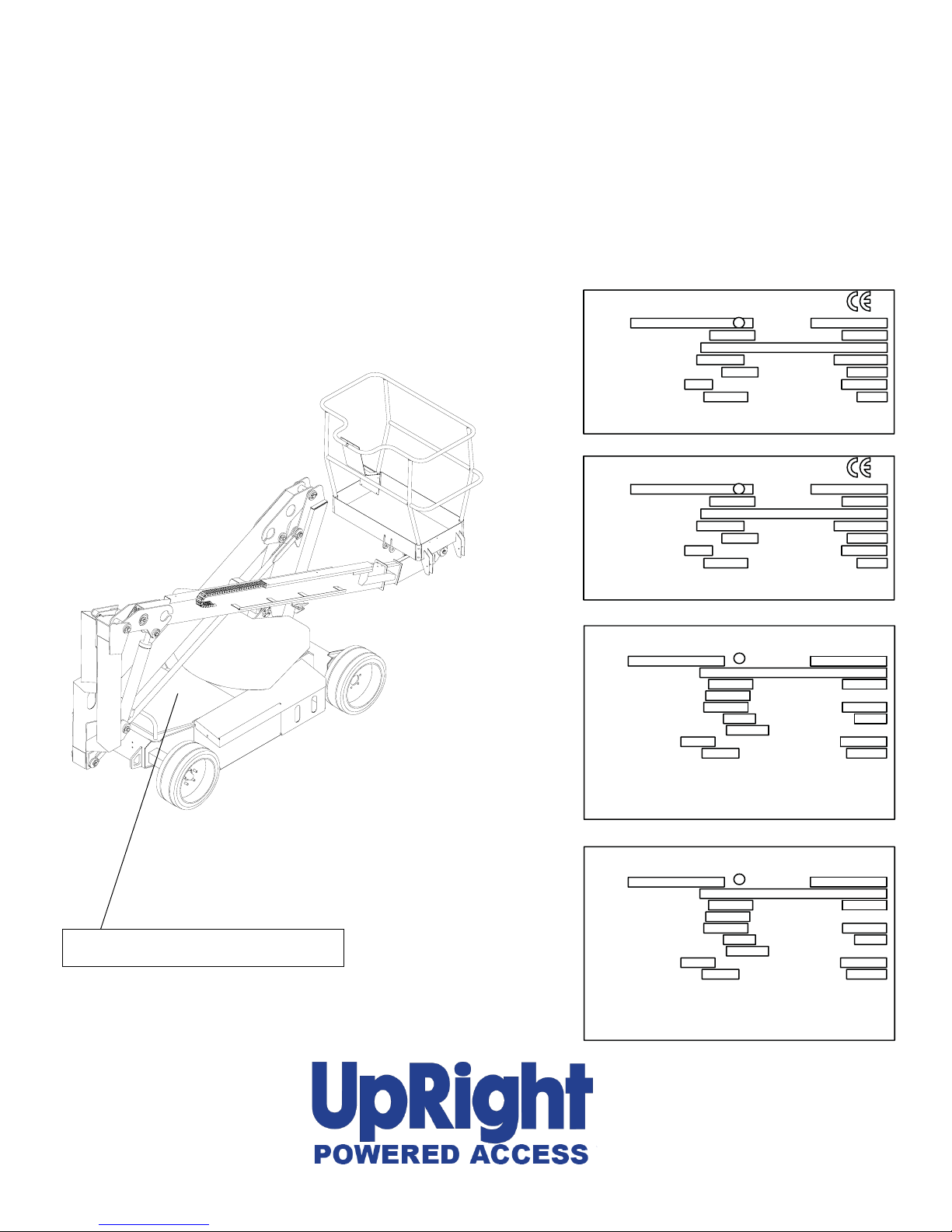
VERIFY that all labels are in place and legible before using.
NEVER use a machine that is damaged, not functioning properly, or has damaged or missing labels.
To bypass any safety equipment is prohibited and presents a danger for the persons on the aerial work platform and in its working
range.
NEVER charge batteries near sparks or open flame. Charging batteries emit explosive hydrogen gas.
Modifications to the aerial work platform are prohibited or permissible only at the approval by UpRight.
AFTER USE, secure the work platform from unauthorized use by turning the keyswitch off and removing key.
The driving of MEWP’s on the public highway is subject to regulations made under the Road Traffic Acts.
ALWAYS use a full body harness, prior to raising the platform, as recommended by the Health and Safety Executive (H1/05/05)
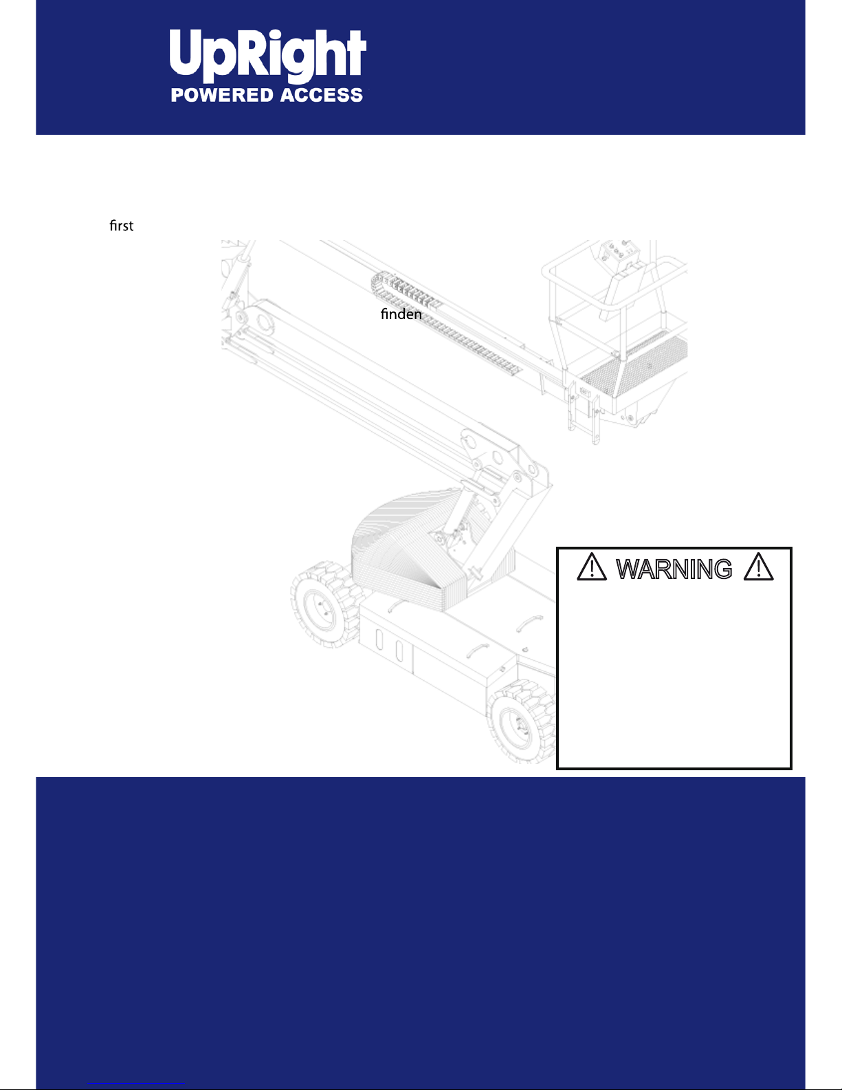
UpRightAB38
NEVER elevate the platform or drive
the machine while elevated unless
the machine is on a firm, level
surface.
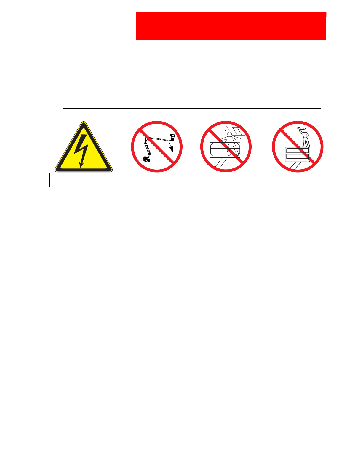
NEVER climb, stand, or sit on
platform guardrails or midrail.
NEVER position the platform
without first checking for overhead
obstructions or other hazards.
Electrocution Hazard Tip
O
ver Hazard
C
ollision Hazard Fall Hazard
THIS MACHINE IS NOT
INSULATED!

Page 2 Operation Manual
C
ONTENTS
Safety Rules. . . . . . . . . . . . . . . . . . . . . . . . . . . . . . . . . . . . . . . . . . . . . . . . . . . . . . . . . . . . . . . . . . . . Page 1
Introduction & General Description. . . . . . . . . . . . . . . . . . . . . . . . . . . . . . . . . . . . . . . . . . . . . . . . . Page 3
Special Limitations . . . . . . . . . . . . . . . . . . . . . . . . . . . . . . . . . . . . . . . . . . . . . . . . . . . . . . . . . . . . . . Page 4
Controls & Indicators . . . . . . . . . . . . . . . . . . . . . . . . . . . . . . . . . . . . . . . . . . . . . . . . . . . . . . . . . . . . Page 5
Pre-Operation & Safety Inspection . . . . . . . . . . . . . . . . . . . . . . . . . . . . . . . . . . . . . . . . . . . . . . . . . Page 5
System Functions . . . . . . . . . . . . . . . . . . . . . . . . . . . . . . . . . . . . . . . . . . . . . . . . . . . . . . . . . . . . . . . Page 6
Operation . . . . . . . . . . . . . . . . . . . . . . . . . . . . . . . . . . . . . . . . . . . . . . . . . . . . . . . . . . . . . . . . . . . . . . Page 6
Emergency Lowering . . . . . . . . . . . . . . . . . . . . . . . . . . . . . . . . . . . . . . . . . . . . . . . . . . . . . . . . . . . . Page 7
Transporting the Machine . . . . . . . . . . . . . . . . . . . . . . . . . . . . . . . . . . . . . . . . . . . . . . . . . . . . . . . . Page 8
Hour Meter . . . . . . . . . . . . . . . . . . . . . . . . . . . . . . . . . . . . . . . . . . . . . . . . . . . . . . . . . . . . . . . . . . . . . Page 8
Maintenance. . . . . . . . . . . . . . . . . . . . . . . . . . . . . . . . . . . . . . . . . . . . . . . . . . . . . . . . . . . . . . . . . . . . Page 9
Battery Maintenance . . . . . . . . . . . . . . . . . . . . . . . . . . . . . . . . . . . . . . . . . . . . . . . . . . . . . . . . . . . . Page 10
Inspection & Maintenance Schedule. . . . . . . . . . . . . . . . . . . . . . . . . . . . . . . . . . . . . . . . . . . . . . . Page 11
Daily Preventative Maintenance Checklist . . . . . . . . . . . . . . . . . . . . . . . . . . . . . . . . . . . . . . . . . . Page 12
Decal Location. . . . . . . . . . . . . . . . . . . . . . . . . . . . . . . . . . . . . . . . . . . . . . . . . . . . . . . . . . . . . . . . . Page 13
Specifications . . . . . . . . . . . . . . . . . . . . . . . . . . . . . . . . . . . . . . . . . . . . . . . . . . . . . . . . . . . . . . . . . Page 14

Introduction
Operation Manual Page 3
I
NTRODUCTION
This manual covers the AB38N and the AB38W Aerial Work Platforms.
This manual must be stored on the machine at all times.
Read, understand and follow all safety rules and operating instructions before attempting to operate the
machine.
G
ENERAL
D
ESCRIPTION
WARNING
!!
DO NOT use the maintenance platform without guardrails properly assembled and in place.
Figure 1: AB38
1. Platform
2. Entry Bar
3. Elevating Assembly
4. Platform Controls
5. Manual Case
6. Lower Controls
7. Hydraulic Reservoir
8. Level Sensor
9. Batteries
10. Emergency Lowering Valves
11. Battery Charger
1
2
3
45
6
7
8
9
10
10
11

Page 4 Operation Manual
Special Limitations
S
PECIAL
L
IMITATIONS
Travel with the platform raised is limited to creep speed range.
Elevating the platform is limited to firm, level surfaces only.
DANGER
! !
The elevating function shall ONLY be used when the work platform is level and on a firm surface.
The work platform is NOT intended to be driven over uneven, rough, or soft terrain.
P
LATFORM
C
APACITY
Two people and tools may occupy the platform. The maximum platform capacity for the AB38N/W is
stated in the ‘Specifications’ on page 14.
DANGER
! !
DO NOT exceed the maximum platform capacity or the platform occupancy limits for this machine.
M
ANUAL
F
ORCE
Manual force is the force applied by the occupants to objects such as walls or other structures outside
the work platform.
The maximum allowable manual force is limited to 200 N (45 lbs.) of force per occupant, with a maximum
of 400 N (90 lbs.) for two occupants.
DANGER
! !
DO NOT exceed the maximum amount of manual force for this machine.
L
IFT
O
VERLOAD
A
LARM
The AB38 is fitted with a load sensing system designed to comply with the requirements of BS EN 280:
2001
If a load equivalent to 90% of safe working load is lifted a fault code “03” will be displayed on the digital
display on the platform control box. If a load which is greater than the safe working load is present in the
basket all machine functions will cease to operate and an acoustic warning will sound. In order to return
to normal operation a load equal to or less than the safe working load must be present in the basket and
the power must be re-cycled, power can be re-cycled by pushing the emergency stop button and
releasing it again.
B
EAUFORT
S
CALE
Never operate the machine when wind speeds exceed 12.5 m/s (28mph) [Beaufort scale 6].
BEAUFORT
RATING
WIND SPEED GROUND CONDITIONS
m/s km/h ft/s mph
3 3,4~5,4 12,25~19,4 11.5~17.75 7.5~12.0 Papers and thin branches move, flags wave.
4 5,4~8,0 19,4~28,8 17.75~26.25 12.0~18 Dust is raised, paper whirls up, and small branches sway.
5 8,0~10,8 28,8~38,9 26.25~35.5 18~24.25 Shrubs with leaves start swaying. Wave crests are apparent in ponds or swamps.
6 10,8~13,9 38,9~50,0 35.5~45.5 24.5~31 Tree branches move. Power lines whistle. It is difficult to open an umbrella.
7 13,9~17,2 50,0~61,9 45.5~56.5 31.~38.5 Whole trees sway. It is difficult to walk against the wind.

Controls and Indicators
Operation Manual Page 5
C
ONTROLS
AND
I
NDICATORS
The operator shall know the location of each control and indicator and have a thorough knowledge of the
function and operation of each before attempting to operate the unit.
Figure 2: Controls and Indicators
P
RE
-O
PERATION
S
AFETY
I
NSPECTION
NOTE: Carefully read, understand and follow all safety rules, operating instructions, labels and National Safety
Instructions/Requirements. Perform the following steps each day before use.
1. Remove the Chassis Covers and inspect for damage, fluid leaks or missing parts.
2. Check the level of the hydraulic fluid with the platform fully lowered. Remove the Chassis Covers and
remove the reservoir cap, fluid should be visible on the dipstick. Add recommended hydraulic fluid if
necessary. See “Specifications” on page 14.
3. Check that the fluid level in the batteries is correct. See “Battery Maintenance” on page 10.
4. Verify that the batteries are charged.
5. Check that the A.C. extension cord has been disconnected from the chassis outlet.
6. Check that all guardrails are in place and all fasteners are properly tightened.
7. Inspect the machine thoroughly for cracked welds and structural damage, loose or missing hardware,
hydraulic leaks, damaged control cable and loose wire connections.
1
2
3
4
5
11
10
9
Lower Controls
456
7
678
1. Emergency Stop
2. Cage Level
3. Upper Boom
4. Lower Boom
5. Drive
6. Horn
7. Slew (Rotate)
8. Display
9. Telescope
10. Joystick
11. Key Switch (on side of box)
Upper Controls
1. Emergency Stop
2. Upper Boom
3. Lower Boom
4. Slew (Rotate)
5. Telescope
6. Enable
7. Analog Rocker
1
2
3

Page 6 Operation Manual
System Function Inspection
S
YSTEM
F
UNCTION
I
NSPECTION
Refer to Figure 1 and Figure 2 for the locations of various controls and indicators.
WARNING
!!
STAND CLEAR of the work platform while performing the following checks.
Before operating the machine, survey the work area for surface hazards such as holes, drop-offs, bumps
and debris.
Check in ALL directions, including above the work platform, for obstructions and electrical conductors.
Protect the control console cable from possible damage while performing checks.
1. Move the machine, if necessary, to an unobstructed area to allow for full elevation.
2. Pull Chassis Emergency Stop Switch to the ON position.
3. Pull Platform Emergency Stop Switch to the ON position.
4. Visually inspect the elevating assembly, lift cylinder, cables, and hoses for cracked welds and structural
damage, loose hardware, hydraulic leaks, loose wire connections, and erratic operation. Check for
missing or loose parts.
5. Test each machine function (Lift, Slew, Telescope) from the lower control station by pressing and
holding the desired function button then moving the Analog Rocker to the Up or Down position (ref:
chassis controls illustration on page 5)
6. Open the Emergency Lowering Valve (see Figure 3) by pulling the knob out to check for proper
operation. When the platform is lowered, release the knob.
7. Push the Chassis Emergency Stop Switch to check for proper operation. All machine functions should
be disabled. Twist the Chassis Emergency Stop Switch to resume.
8. Climb onto the cage.
9. Check that the route is clear of obstacles (persons, obstructions, debris), is level, and is capable of
supporting the wheel loads.
10. Mount the platform and properly close the drop bar.
11. Test each machine function (Drive, Lift, Slew, Telescope, Platform Rotate, Cage Level) from the upper
control station by pressing the desired function button then moving the Joystick to the Forward or Back
position (ref: platform controls illustration on page 5)
12. Push the Platform Emergency Stop Switch to check for proper operation. All machine functions should
be disabled. Pull out the Platform Emergency Stop Switch to resume.
O
PERATION
Before operating the work platform, ensure thatthe Pre-Operation Safety Inspection has been completed
and that any deficiencies have been corrected. Never operate a damaged or malfunctioning
machine. The operator must be thoroughly trained on this machine.
E
LEVATING
THE
P
LATFORM
1. Select either the lower or upper boom lift function button (the button will illuminate to confirm
selection).
2. While engaging the Interlock Switch, push the Control Handle forward.
3. If the machine is not level the tilt alarm will sound and the machine will not lift.
L
OWERING
THE
P
LATFORM
1. Select either the lower or upper boom lift function button (the button will illuminate to confirm
selection).
2. While engaging the Interlock Switch, pull the Control Handle backwards.
3. If the machine is not level the tilt alarm will sound and the machine will only descend.

Operation
Operation Manual Page 7
R
OTATING
THE
P
LATFORM
1. Select the rotate function button (the button will illuminate to confirm selection).
2. While engaging the Interlock Switch, move the Control Handle forwards or backwards to achieve
clockwise or counter clockwise rotation.
3. If the machine is not level the tilt alarm will sound and the machine will not rotate.
O
PERATING
THE
T
ELESCOPE
1. Select telescope function button (the button will illuminate to confirm selection).
2. While engaging the Interlock Switch, move the Control Handle forwards or backwards to extend or retract
the telescopic boom.
3. If the machine is not level the tilt alarm will sound and the telescope boom will only retract.
NOTE: The AB38W is equipped with a safety system preventing any drive motion when the machine is out of the stow
position and with the telescope extended beyond a pre-set limit.
L
EVELLING
THE
CAGE
1. Select platform level function button (the button will illuminate to confirm selection).
2. While engaging the Interlock Switch, move the Control Handle forwards or backwards to adjust the floor
angle of the cage (this can only be done when the machine is in the stowed position).
3. If the machine is not level the tilt alarm will sound and the machine will not operate.
E
MERGENCY
L
OWERING
WARNING
!!
If the platform should fail to lower, NEVER climb down the elevating assembly.
Stand clear of the elevating assembly while operating the Emergency Lowering Valve Knob.
Figure 3: Emergency Lowering Valve
Ask a person on the ground to open the Emergency
Lowering Valve to lower the platform. The Emergency
Lowering Valve is located on the base of each lift
cylinder.
1. Open the Emergency Lowering Valve by pulling the
knob out.
2. To close, release the knob.
NOTE: The platform will not elevate if the Emergency Lowering
Valve is open.
A
FTER
U
SE
E
ACH
D
AY
1. Ensure that the platform is fully lowered.
2. Park the machine on a firm level surface, preferably under cover, secure against vandals, children and
unauthorized operation.
3. Turn the Chassis Key Switch to OFF and remove the key to prevent unauthorized operation.
Emergency Lowering Valves

Page 8 Operation Manual
Transporting the Machine
T
RANSPORTING
THE
M
ACHINE
B
Y
C
RANE
Secure the straps to chassis lifting/tie down points only.
B
Y
F
ORKLIFT
DANGER
! !
Forklifting and Lifting by Crane are for transport only.
See specifications for weight of machine and be certain that forklift is of adequate capacity to lift the
machine.
Figure 4: Transporting the Machine
Forklift from the side by lifting under the Chassis.
B
Y
T
RUCK
1. Maneuver the machine into transport position
and chock wheels.
2. Secure the machine to the transport vehicle with
chains or straps of adequate load capacity
attached to the chassis lifting/tie down points.
CAUTION
Over tightening of the chains or straps attached to
the Tie Down lugs may result in damage to the
machine
H
OUR
M
ETER
To access the hour meter function perform the following steps.
1. Climb into the basket (with the machine powered up)
2. Push the platform emergency stop button.
3. Hold down the following buttons, Horn, Telescope & Upper Boom Lift.
4. While holding the buttons twist the emergency stop button to return power to the machine.
5. “hr” will now be displayed on the read-out, Pressing the right turn button will scroll through the
accumulated hours two digits at a time. For example, if pressing the right turn button once displays “20”,
pressing it a 2nd time displays “58”, and pressing it a 3rd time displays “hr”, the elapsed time of operation
is 2058 hours.
Lift / Tie Down Points

Maintenance
Operation Manual Page 9
M
AINTENANCE
WARNING
!!
Never perform service while the platform is elevated.
H
YDRAULIC
F
LUID
The hydraulic fluid reservoir is located in the chassis door.
Figure 5: Hydraulic Fluid Reservoir and Dipstick
NOTE: Never add fluid if the platform is elevated.
C
HECK
H
YDRAULIC
F
LUID
1. Make sure that the platform is fully lowered.
2. Open the chassis door.
3. Remove the filler cap from the hydraulic fluid reservoir.
4. Check the fluid level on the dipstick on the filler cap.
5. Add the appropriate fluid to bring the level to show on
the dipstick. See “Specifications” on page 14
Filler Cap

Page 10 Operation Manual
Maintenance
B
ATTERY
M
AINTENANCE
Figure 6: Access to Batteries
WARNING
!!
Hazard of explosive gas mixture. Keep sparks, flame,
and smoking material away from batteries.
Always wear safety glasses when working near
batteries.
Battery fluid is highly corrosive. Thoroughly rinse away
any spilled fluid with clean water.
Always replace batteries with UpRight batteries or
manufacturer approved replacements weighing 26,3 kg
(58 lbs.) each.
• Check the battery fluid level daily, especially if the
machine is being used in a warm, dry climate.
• If electrolyte level is lower than 10 mm (3/8in.) above the plates add distilled water only. DO NOT use
tap water with high mineral content, as it will shorten battery life.
• Keep the terminals and tops of the batteries clean.
• Refer to the Service Manual to extend battery life and for complete service instructions.
B
ATTERY
C
HARGING
Figure 7: Battery Charge Indicator
Charge the batteries at the end of each work shift or
sooner if the batteries have been discharged.
WARNING
!!
Charge the batteries in a well ventilated area.
Do not charge the batteries when the machine is near
a source of sparks or flames.
Permanent damage to the batteries will result if the
batteries are not immediately recharged after
discharging.
Never leave the battery charger operating for more than two days.
Never disconnect the cables from the batteries when the charger is operating.
Keep the charger dry.
1. Check the battery fluid level. If the battery fluid level is lower than 10 mm (3/8in.) above the plates add
distilled water only.
2. Connect an appropriate extension cord to charger outlet plug in Right Module Door. Plug the extension
cord into a properly grounded outlet of proper voltage and frequency.
3. The charger turns on automatically after a short delay. The LED charge indicator will illuminate. After
completion of the charge cycle the LED will blink, indicating that the charger is in a continuing
maintenance mode. DO NOT leave the charger plugged in for more than 48 hours, as permanent
damage to the batteries may occur.
NOTE: The battery charger circuit must be used with a GFI (Ground Fault Interrupt) outlet.
NOTE: DO NOT operate the machine while the charger is plugged in.
Battery
Charge
Indicator

Inspection and Maintenance Schedule
Operation Manual Page 11
I
NSPECTION
AND
M
AINTENANCE
S
CHEDULE
The Complete Inspection consists of periodic visual and operational checks, along with periodic minor
adjustments that assure proper performance.
Daily inspection will prevent abnormal wear and prolong the life of all systems. The inspection and
maintenance schedule should be performed at the specified intervals. Inspection and maintenance shall be
performed by personnel who are trained and familiar with mechanical and electrical procedures.
WARNING
!!
Before performing preventative maintenance, familiarize yourself with the operation of the machine.
Always block the elevating assembly whenever it is necessary to perform maintenance while the
platform is elevated.
The daily preventative maintenance checklist has been designed for machine service and maintenance.
Please photocopy the Daily Preventative Maintenance Checklist and use the checklist when inspecting the
machine.

Page 12 Operation Manual
Daily Preventative Maintenance Checklist
D
AILY
P
REVENTATIVE
M
AINTENANCE
C
HECKLIST
M
AINTENANCE
T
ABLE
K
EY
Y= Yes/Acceptable
N= No/Not Acceptable
R= Repaired/Acceptable
P
REVENTATIVE
M
AINTENANCE
R
EPORT
Date: _______________________________________
Owner:______________________________________
Model No: ___________________________________
Serial No:____________________________________
Serviced By: _________________________________
___________________________________________
COMPONENT INSPECTION OR SERVICES Y N R
Battery Check electrolyte level.
Check battery cable condition.
Chassis Check hoses for pinch or rubbing points.
Check welds for cracks.
Control Cable Check the exterior of the cable for pinching, binding or wear.
Controller Check switch operation.
Drive Motor/Gearbox Check for operation and leaks.
Elevating Assembly Inspect for structural cracks.
Emergency Hydraulic System Operate the emergency lowering valve and check for serviceability.
Entire Unit Check for and repair collision damage.
Hydraulic Fluid Check fluid level.
Hydraulic Pump Check for hose fitting leaks.
Hydraulic System Check for leaks.
Labels Check for peeling, missing, or unreadable labels & replace.
Platform Deck and Rails Check welds for cracks.
Platform Deck and Rails Check condition of deck.
Tires Check for damage.

Decal Location
Operation Manual Page 13
D
ECAL
L
OCATION
ITEM PART NO. DESCRIPTION QTY.
1 500264-000 DECAL - UpRight AB38 BOOM 2
2 501870-000 DECAL - LOWER CONTROL BOX 1
3 500257-000 DECAL - AB38 LOGO 1
4 057695-000 DECAL - BALLAST STRIP 1
5 502480-000 DECAL - EMERGENCY LOWERING 2
6 057696-000 DECAL - ‘UpRight’ LOGO 2
7 057429-000 DECAL - BATTERY FLUID LEVEL 2
8 057430-000 DECAL - EXPLOSION HAZARD 2
9 057692-000 DECAL - IMPORTANT BEFORE USING 1
10 058472-000 NAMEPLATE 1
11 500467-000 DECAL - HANDPUMP 1
12 058881-001 DECAL - HAZARD TAPE 2
13 058080-000 DECAL - CAGE LEVELLING 1
14 058186-000 DECAL - ON/OFF UPPER CONTROL 1
15 500423-006 OPERATOR MANUAL CE 1
16 501869-000 DECAL - UPPER CONTROL BOX 1
17 058181-000 DECAL - 3 POINT 1
18 057392-000 DECAL - S.W.L. LARGE 1
19 058860-000 DECAL - PINCH POINT 2
20 500438-000 DECAL - LOWER CONTROL COVER 1
21 500422-006 SERVICE & PARTS MANUAL 1

Page 14 Operation Manual
Specifications
S
PECIFICATIONS
Table 1-1 : Specifications
ITEM METRIC IMPERIAL
Duty Cycle 45% of 8 hour s hift
Platform Size 0.7 m x 1.3 m (inside guardrails)
Max. Platform Capacity
CE V er s ion 200kg (W) or 215kg (N) 441lbs(W) or 475lbs (N)
ANSI Version 215 kg 475 lbs
Max. Number of Occupants 2 People 2 People
Height
Maximum Working Height 13.45 m 44.12 ft
Maximum Platform Height 11.45 m 37.56 ft
Min. Platform Floor Height 0.65 m 2.13 ft
Max. Working Outreach 6.10 m 20.00 ft
Platform Height at
Maximum Outreach 5.40 m 17.72 ft
Stowed Dimensions
Length 4.04 m 13.25 ft
Width 1.72m (W) or 1.5m (N) 5.61ft (W) or 4.92 ft (N)
Height 2.00 m 6.56 ft
Ground Clearence 0.13 m 0.43 ft
Wheel Base X Guage 2.00m x 1.49m (W) or 1.27m (N) 6.56 ft (W) x 4.16 ft (N)
Rotation 362 degrees non-continuous 362 degrees non-continuous
Gross Weight-CE Version 3200kg (W) or 3800kg (N) 7055lbs (W) or 8378lbs (N)
Gross Weight-ANSI Version 3400kg (W) or 4108kg (N) 7496lbs (W) or 9057lbs (N)
Drive Speed Stowed 0 - 4 km/h 0 - 2.49 mph
Drive Speed Elevated 0 - 0.72 km/h 0 - 0.45 mph
Maximum Gradeability 36% 36%
Inside Turning Radius 0.40 m 1.31 ft
Outside Turning Radius 2.66 m (W) or 2.4 m (N) 8.72ft (W) or 7.87ft (N)
Power Source 48V DC 4kw, 8 x 6V 220Ah Batteries 48V DC 5.4 HP, 8 x 6V 220Ah Batteries
System Voltage 48V 48V
Battery Charger 48V 25A 220/110VAC 50/60 Hz 48V 25A 220/110VAC 50/60 Hz
Hydraulic Tank Capacity 25 Litres 6.5 Gallons US
Max. Hydraulic Pressure 175 bar 2540 psi
Hydraulic Oil ISO #46 ISO #46
Lift System 2 Double acting lift cylinders with 2 Double acting lift cylinders with
Lock Valves and Manual Emergency Lock Valves and Manual Emergency
Lowering Facility. Lowering Facility.
1 Double Acting Telescopic Cylinder 1 Double Acting Telescopic Cylinder
Control System One handed Proportional Joystick One handed Proportional Joystick
Operating Energy Efficient Motor Operating Energy Efficient Motor
Control System Control System
Wheels/Tyres 400 mm Diameter Steel Disc Wheel 15.75 inch Diameter Steel Disc Wheel
with Solid all Surface tyres with Solid all Surface tyres
Braking Automatic Spring Applied Automatic Spring Applied
Hydraulic Release Hydraulic Release
Sound Pressure Level at 70 db(A) 70 db(A)

CAUTION:ONLY TRAINED & AUTHORISED PERSONNEL MAY USE
THIS MACHINE-CONSULT OPERATORS MANUAL BEFORE USE.
THIS PLATFORM IS NOT ELECTRICALLY INSULATED
200kg 2 Persons + 40kg. Equipment
1.1 m/s
400N
MAX. GRADEABILITY 36%
MAX. FORWARD SPEED
MAX. PLATFORM HEIGHT
MAX. PLATFORM LOAD
MAX. LATERAL FORCE
MAX. CHASSIS INCLINATION
CHARGER INPUT VOLTAGE 240V
NOMINAL POWER
58472-008
4kW
BATTERY VOLTAGE
UNLADEN WEIGHT
MAX. WIND SPEED
0°
11.5m
12.5 m/s
48V
3200 kg
UpRight
MODEL AB38W
VIGO CENTRE
TYNE & WEAR, UK.
SERIAL No.
WASHINGTON,
AB38N
MODEL SERIAL No.
BATTERY VOLTAGE
NOMINAL POWER
UNLADEN WEIGHT
MAX. WIND SPEED
CHARGER INPUT VOLTAGE
CAUTION:ONLY TRAINED & AUTHORISED PERSONNEL MAY USE
THIS MACHINE-CONSULT OPERATORS MANUAL BEFORE USE.
THIS PLATFORM IS NOT ELECTRICALLY INSULATED
215kg 2 Persons + 55kg. Equipment
36%
MAX. GRADEABILITY
MAX. FORWARD SPEED 1.1 m/s
MAX. PLATFORM HEIGHT
MAX. PLATFORM LOAD
MAX. LATERAL FORCE
MAX. CHASSIS INCLINATION
400N
0°
11.5m
240V
58472-000
4kW
12.5 m/s
48V
3800 kg
VIGO CENTRE
TYNE & WEAR, UK.
WASHINGTON,
UpRight
18ft 4in
2105psi
CHARGER INPUT VOLTAGE
475 lbs (2 PERSONS + 120 lbs)
THIS PLATFORM IS NOT ELECTRICALLY INSULATED
THIS MACHINE-CONSULT OPERATORS MANUAL BEFORE USE.
CAUTION: ONLY TRAINED & AUTHORISED PERSONNEL MAY USE
THIS MACHINE IS MANUFACTURED TO COMPLY WITH
ANSI A92.5 - 1992
2.5mph
MAX. FORWARD SPEED
MAX. PLATFORM REACH
BATTERY VOLTAGE
MAX. LATERAL FORCE
MAX. HYDRAULIC PRESSURE
MAX. CHASSIS INCLINATION 0°
48V dc
90 lbs
UpRight
MAX. PLATFORM HEIGHT
MAX. PLATFORM LOAD
MODEL AB38N
38 ft
58472-002
5.4 hp
NOMINAL POWER
110/120V
28 mph
MAX. GRADEABILITY
MAX. WIND SPEED
36%
VIGO CENTRE
9057 lbs
SERIAL No.
UNLADEN WEIGHT
TYNE & WEAR, UK.
WASHINGTON,
5.4 hp
NOMINAL POWER
2.5mph
MAX. FORWARD SPEED
THIS PLATFORM IS NOT ELECTRICALLY INSULATED
THIS MACHINE-CONSULT OPERATORS MANUAL BEFORE USE.
CAUTION: ONLY TRAINED & AUTHORISED PERSONNEL MAY USE
THIS MACHINE IS MANUFACTURED TO COMPLY WITH
ANSI A92.5 - 1992
58472-006
CHARGER INPUT VOLTAGE
MAX. GRADEABILITY
MAX. WIND SPEED
UNLADEN WEIGHT
475 lbs (2 PERSONS + 120 lbs)
VIGO CENTRE,
UpRight
BATTERY VOLTAGE
MAX. HYDRAULIC PRESSURE
MAX. CHASSIS INCLINATION
MAX. LATERAL FORCE
MAX. PLATFORM REACH
MAX. PLATFORM HEIGHT
MAX. PLATFORM LOAD
MODEL
90 lbs
18ft 4in
48V dc
0°
2105psi
38 ft
AB38W SERIAL No.
TYNE & WEAR, UK
WASHINGTON,
36%
110/120V
28 mph
7496 lbs
DEUTSCH
Wenn Sie mit UpRight Kontakt aufnehmen, um Informationen zu Serviceleistungen oder Ersatzteilen zu erhalten, achten
Sie bitte darauf, MODELL- und SERIENNUMMER anzugeben. Sie finden beide Nummern auf dem Typenschild der Anlage.
Sollte das Typenschild fehlen, können Sie die SERIENNUMMER auch auf dem Fahrwerk über der vorderen Schwenkachse
ablesen.
AB38
Seriennummer 3700 – aktuell
Seriennummer, auf dem Fahrwerkboden
unter dem Lenkzylinder eingestanzt.
www.upright.com

Other manuals for AB38
3
Table of contents
Languages:
Other Upright Boom Lift manuals

Upright
Upright AB38 User manual

Upright
Upright AB60JRT User manual

Upright
Upright TL37 Guide

Upright
Upright AB48 HSRT User manual

Upright
Upright MB20N Guide

Upright
Upright MB20N User manual

Upright
Upright AB46 I Guide

Upright
Upright TL50 Guide

Upright
Upright AB46RT User manual

Upright
Upright TL49K User manual