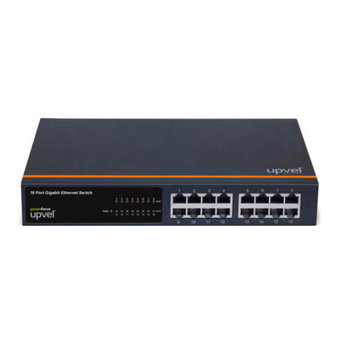
Upvel UP-236FEF User manual


UP-236FEF
For instruction in English, see pages 2-8.
Инструкция на русском языке – со страницы 9.
Quick Installation Guide 1

UP-236FEF
Package Contents
•UP-236FEF switch
•Power cord
•19-inch rack mounting kit: L-brackets (2 pcs) and screws (8 pcs)
•Rubber feet (4 pcs)
•Quick Installation Guide
Note.If any of the listed items are damaged or missing, please contact
your distributor.
External Components Description
Front panel
1~16:RJ45 100 Mbps PoE+ ports
17T: RJ45 Gigabit uplink port
17S: SFP slot (shared with 17Tgigabit uplink port)
Power: Power LED indicator
LNK/ACT 1~16, 17T/S:Connection/activity LEDs of the
corresponding ports
PoE 1~16: PoE-enabled device connection LEDs of the
corresponding ports
2 Quick Installation Guide

UP-236FEF
LED Description
Rear panel
The rear panel of the switch contains the AC power connector and grounding
terminal. The switch supports 100~240 V AC, 50~60 Hz, 2.5 A max.
Indicator
Color
Status
Description
Power Green
On
Power on
Off
Power off
LNK/ACT Green
On
Connection is established
Off
Connection is not established
Flashing
Data is being transmitted
PoE Orange
On
PoE-enabled device is detected,
sufficient power is supplied
successfully
Flashing
The power is insufficient for
operation of PoE device
Off
PoE-enabled device is not
connected/detected
Quick Installation Guide 3

UP-236FEF
Installation
Installation Site Requirements
Ensure that the location where you plan to install the switch meets the
following requirements:
•Air temperature and humidity should be within the specified ranges.
See technical specifications on page 7.
•Vent holes in the switch housing should not be blocked. Make sure
that there is enough space around the switch for proper ventilation
and heat dissipation. Leave at least 10 cm (4 inches) of space at the
front and rear of the switch.
•The outlet should be close enough for the power cord to reach. The
length of the power cord supplied is 150 cm (59 inches).
•Desktop installation:place the switch on a sturdy, level surface
that can support at least 5 kg (11 lbs). For better stability, stick four
rubber feet to the bottom of the switch near the corners.
•Rack mounting: attach the brackets to the switch using the
included screws and then mount the switch on the 19-inch rack using
the screws provided with the rack.
Power connection
1. Connect one end of the power cord to the AC power connector on
the rear panel of the switch, and then connect the other end of the
power cord to an AC power outlet.
2. Check whether the Power LED is ON. When it is steady ON, it
indicates the power connection works properly.
4 Quick Installation Guide

UP-236FEF
Connecting to end nodes
Use standard Cat.5/5e/6 twisted pair cable (UTP/STP) to connect the
switch to end nodes. Switch ports will automatically adjust to the
characteristics (MDI/MDI-X, speed, duplex) of the connected devices.
Quick Installation Guide 5

UP-236FEF
Troubleshooting
The LEDs on the front panel can help you diagnose network failures. This
section describes common problems and ways to fix them.
1. If the LNK/ACT LED is off after connecting a device:
•check the network interfaces of the connected device and the
switch;
•make sure that the network cable is not damaged and is firmly
connected to the ports of both network interfaces (of the switch
and the device you intend to connect);
•make sure that the length of the cable does not exceed the
specified limit (100 meters / 328 feet).
2. If the Power LED is off after plugging the power cord into the AC
power connector of the switch and into the mains outlet:
•check the presence of power in the outlet;
•make sure that the power cord is not damaged and is firmly
plugged into the AC power connector of the switch and into the
mains outlet.
3. If the Power LED lights up after plugging the power cord, but then
turns off after a while:
•check that there are no excessive voltage drops in your electric
grid;
•make sure the power cable is not tightened (it can cause
inadvertent unplugging).
If the above steps do not resolve the problem, please contact
the service center.
6 Quick Installation Guide

UP-236FEF
Specifications
UP-236FEF
Chipset
IP1818+IP108A+IP1001+IP403+PD69008
Standards
IEEE 802.3 10BASE-T
IEEE 802.3u 100BASE-TX
IEEE 802.3ab 1000BASE-T
IEEE 802.3z 1000BASE-X
IEEE 802.3af Power over Ethernet (PoE)
IEEE 802.3at Power over Ethernet (PoE+)
IEEE 802.3x Flow Control
IEEE 802.3az Energy Efficient Ethernet
Ports
16 x RJ45 100 Mbps PoE+ ports
1 x RJ45 1000 Mbps uplink port
1 x SFP slot (uplink)
Power over Ethernet
Up to 30 W per port
Power budget: 240 W
PoE pins on RJ45: 1&2 (+), 3&6 (-), mode A
Data Throughput
Ethernet: 10 / 20 Mbps (half / full duplex)
Fast Ethernet: 100 / 200 Mbps (half / full duplex)
Gigabit Ethernet: 1000 / 2000 Mbps (half / full duplex)
Packet Forwarding Rate
Ethernet: 14 880 pps
Fast Ethernet: 148 800 pps
Gigabit Ethernet: 1 488 000 pps
Switching Method
Store-and-Forward
Switching Capacity
5.2 Gbps
MAC Address Table
4K entries, auto-learning & auto-aging
LED Indicators
Power, PoE, Link/Activity
AC Input
100~240 V AC, 50~60 Hz, 2.5 A max., internal power supply
Power Consumption
260 W (max.)
Dimensions
442 × 208 × 44 mm (17.4 × 8.2 × 1.7 inch)
Weight
3.5 kg (7.72 lbs)
Temperature
Operating: 0 ~ 40 °C (32 ~ 104 °F)
Storage: -10 ~ 70 °C (14 ~ 158 °F)
Humidity
Max. 90 % (non-condensing)
Certification
CE, FCC, Rostest
Quick Installation Guide 7

UP-236FEF
International support
support@upvel.com
+1-323-6290485 (USA)
Mon-Fri (ex. public holidays)
8 Quick Installation Guide

UP-236FEF
Комплект поставки
•Коммутатор UP-236FEF
•Шнур питания
•Кронштейны (2 шт.) и винты (8 шт.) для монтажа коммутатора в
19-дюймовую стойку
•Резиновые ножки (4 шт.)
•Инструкция по установке
Примечание. Если какой-либо компонент отсутствует или
поврежден, обратитесь к продавцу.
Описание внешних элементов
Передняя панель
1~16:порты RJ45 10/100 Мбит/с PoE+
17T: порт RJ45 1000 Мбит/с (uplink)
17S: слот для SFP-модуля (uplink)
Power:индикатор питания
LNK/ACT 1~16, 17T/S: индикаторы наличия/активности соединения
PoE 1~16:индикаторы подключения устройств с поддержкой PoE
Quick Installation Guide 9

UP-236FEF
Значения индикации
Задняя панель
На задней панели коммутатора находится разъем питания
100~240 V AC, 50~60 Hz, 2.5 A max. иклемма заземления.
Индикатор
Цвет
Состояние
Значение
Power Зеленый
Горит
непрерывно Питание включено
Не горит
Питание отключено
LNK/ACT Зеленый
Горит
непрерывно
К порту подключено устройство /
соединение с устройством
установлено
Не горит
Устройство не подключено к порту
/ соединение с устройством не
установлено
Мигает
Прием / передача данных
PoE Зеленый
Горит
непрерывно
Обнаружено устройство с
поддержкой технологии PoE,
питание подается
Мигает
Недостаточно мощности для
работы подключенного устройства
Не горит
Устройство с поддержкой
технологии PoE не подключено или
не обнаружено
10 Quick Installation Guide

UP-236FEF
Установка и подключение
Требования к месту установки
•Температура и влажность воздуха в помещении, где будет
установлен коммутатор, должны лежать в диапазонах
допустимых значений, указанныхв таблице технических
характеристик (см. стр. 14).
•Вентиляционные отверстия в корпусе не должны быть
перекрыты.
•Вокруг коммутатора должно быть достаточно свободного
пространства для обеспечения нормальной циркуляции воздуха и
отвода тепла.
•Если коммутатор не будет монтироваться в стойку, то его
следует установить на ровную горизонтальную поверхность,
способную выдерживать вес не менее 5 кг. Для лучшей
устойчивости коммутатора приклейте четыре резиновые ножки к
отмеченным местам на нижней стороне корпуса.
•Расстояние между разъемом питания коммутатора и розеткой
электросети должно быть не более 150 см.
Подключение к электросети
1. Подсоедините прилагаемый шнур питания к разъему на задней
панели коммутатора.
2. Включите шнур питания в розетку сети переменного тока
100~240 V AC, 50~60 Hz.
3. Проверьте состояние индикатора Power на передней панели
коммутатора. При наличии стабильного питания данный
индикатор должен непрерывно гореть.
Quick Installation Guide
11

UP-236FEF
Подключение устройств
Для подключения устройств к коммутатору используйте кабель
UTP/STP категории 5, 5e или 6. Порты коммутатора автоматически
согласуют необходимые параметры (MDI/MDI-X, скорость
соединения, дуплексный/полудуплексный режим) с Ethernet-
интерфейсами подключенных устройств.
12 Quick Installation Guide

UP-236FEF
Выявление и устранение неполадок
Светодиодные индикаторы на передней панели коммутатора помогут
вам выявить неполадки в вашей сети. Ниже рассмотрены типичные
проблемы, которые могут возникнуть при эксплуатации коммутатора,
иданы рекомендации по их устранению.
1. Индикатор LNK/ACT не горит после подключения устройства:
•проверьте состояние сетевых интерфейсов подключенного
устройства и коммутатора;
•убедитесь, что сетевой кабель надежно подключен кпорту
коммутатора и кпорту подключаемого устройства;
•убедитесь в отсутствии повреждений сетевого кабеля;
•длина сетевого кабеля между устройством и коммутатором не
должна превышать100 метров.
2. Индикатор Power не горит после подключения шнура питания к
разъему питания коммутатора икрозетке электросети.
•убедитесь, что в розетке есть напряжение;
•убедитесь, что шнур питания не повреждён.
3. Индикатор Power горит, но коммутатор периодически
самопроизвольно выключается:
•убедитесь, что в вашей электросети нет сильных перепадов
напряжения;
•убедитесь, что шнур питания не натянут. Сильноенатяжение
шнура может привести к разбалтыванию соединителя в
разъеме питания коммутатора и пропаданию контакта.
Если перечисленные меры не помогают устранить проблему,
обратитесь в сервисный центр.
Quick Installation Guide
13

UP-236FEF
Технические характеристики
UP-236FEF
Чипсет
IP1818+IP108A+IP1001+IP403+PD69008
Стандарты
IEEE 802.3 10BASE-T
IEEE 802.3u 100BASE-TX
IEEE 802.3ab 1000BASE-T
IEEE 802.3z 1000BASE-X
IEEE 802.3af Power over Ethernet (PoE)
IEEE 802.3at Power over Ethernet (PoE+)
IEEE 802.3x Flow Control
IEEE 802.3az Energy Efficient Ethernet
Порты
16 портов RJ45 100 Мбит/с PoE+
1 порт RJ45 1000 Мбит/с (uplink)
1 слот для SFP модуля (uplink)
Power over Ethernet
До 30 Вт на порт
Суммарная мощность PoE: 240 Вт
Контакты RJ45: 1 и 2 (+), 3 и 6 (-), метод A
Скорость передачи
данных
Ethernet: 10 / 20 Мбит/с (полудуплекс / дуплекс)
Fast Ethernet: 100 / 200 Мбит/с (полудуплекс / дуплекс)
Gigabit Ethernet: 1000 / 2000 Мбит/с (полудуплекс / дуплекс)
Скорость обслуживания
пакетов
Ethernet: 14 880 пакетов в секунду
Fast Ethernet: 148 800 пакетов в секунду
Gigabit Ethernet: 1 488 000 пакетов в секунду
Метод коммутации
С промежуточным хранением (Store-and-Forward)
Внутренняя пропускная
способность
5.2 Гбит/с
Размер таблицы
MAC-адресов
4096 записей, автоматическое определение и запоминание
новых MAC-адресов иудаление старых MAC-адресов
Светодиодные
индикаторы
Power, PoE, Link/Activity
Питание
100~240 V AC, 50~60 Hz, макс. 2.5 A,
встроенный блок питания
Потребляемая мощность
Не более 260 Вт
Размеры
442 × 208 × 44 мм
Масса
3.5 кг
Допустимая температура
воздуха
При работе: 0 ~ 40 °C
При хранении: -10 ~ 70 °C
Допустимая влажность
воздуха
Не более 90 % (без конденсации)
Сертификаты
CE, FCC, Ростест
14 Quick Installation Guide

UP-236FEF
Техническая поддержка UPVEL в России
8 (495) 952-52-43
8 (800) 555-52-43
support@upvel.ru
Режим работы: 10.00-19.00
(кроме выходных и государственных праздников)
Quick Installation Guide
15


Table of contents
Languages:
Other Upvel Network Router manuals
Popular Network Router manuals by other brands

Asus
Asus BLUE CAVE AC2600 quick start guide

Redline Communications
Redline Communications RDL-2000 user manual

NETGEAR
NETGEAR DG834 - ADSL Firewall Router Features guide

Supermicro
Supermicro SSE-G2252 installation manual

KTI Networks
KTI Networks 10BASE-T/100BASE-TX user guide

Sanyo
Sanyo VAC-900 instruction manual

Motorola
Motorola Netopia 2247NWG reference guide

SMC Networks
SMC Networks 7908VOWBRA2 Quick installation guide

B&B Electronics
B&B Electronics Elinx EIR508 Series quick start guide

Philips
Philips SNB6500 user manual

D-Link
D-Link Express EtherNetwork DI-604 Quick installation guide

H3C
H3C MSR 30-16 installation manual