manuals.online logo
Brands
  1. Home
  2. •
  3. Brands
  4. •
  5. Urban Coop Company
  6. •
  7. Farm Equipment
  8. •
  9. Urban Coop Company Round-Top Mobile Chicken Coop User manual

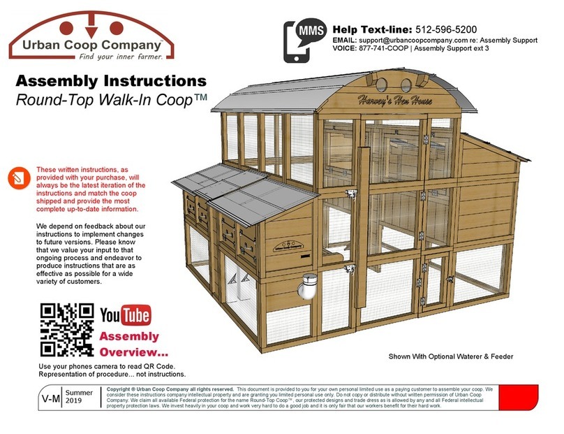
Urban Coop Company Round-Top Mobile Chicken Coop User manual

Thank you for
purchasing your
new Round-Top
Mobile Chicken
Coop!
PLEASE READ... as we want your assembly experience to be fun and as
frustration free as possible.
It has been our experience that if you will read through these instructions first, then identify
and lay out each part of your package using the parts identification pages in these
instructions, assembly is more trouble free. The more options you order, the more
important this becomes as these coops are quite large, and you may become confused by
panels that look similar.
You should expect extra fasteners to be left over. In the rare occasion that we either mis-
manufactured a part, a part was damaged in shipping, or we forgot to package a needed
part, contact us, and we will FedEx a replacement part to you.
There are also helpful assembly videos that can be found on the product page of your
coop at , and you can of course contact us at 877-741-2667. www.urbancoopcompany.com
We can solve most issues you might have over the phone.
Urban Coop Company
TM
Find your inner farmer Assembly Instructions
V 08.09.16 Copyright Urban Coop Company, all rights reserved. Do not duplicate by any means except for personal non-commercial use or
distribute without prior written permission of the Urban Coop Company. Contact us at [email protected] or call 877-741-COOP with any
questions or concerns.
The Round-Top Mobile Chicken Coop™ design and/or accessories may be protected by a federal copyright and/or a pending federal
design patent(s).
Round-Top Mobile Chicken Coop Assembly Instructions
Parts List:
Coop Comes In 2 Boxes
A. Run Panels
1) Sides 2x (beveled top edge)
2) Back (no door)
3) Front (has door)
B. Roost
1) Sides 2x (has wing panels)
2) End (egg box end)
3) End
4) Roost Bars 2x
5) Eave Boards 2x
6) Roof Panel
C. Egg Box
1) Front (has hole)
2) Bottom Wire (square)
2) Bottom Sides 2X
3) Entry Exit Board
D. Misc. Parts
1) Optional Waterer, Bracket & 2
Green Screws
2) Optional Feeder & Hasp
3) Handhold Brackets 4x
4) Handhold Bars 2x
E. Fasteners
1) 3” Brown T25 Screws
2) 1 5/8” Green T20 Screws
3) Rubber Washer Roof Screws
4) 2 1/2” Gold T-20 Screws
Note: Extra screws are provided in
case you lose one, or we goofed in
counting.
F. Tools Provided
1) T25, T20 Torx Bits
2) Magnetic Bit Holder
3) #2 Phillips Bit
G. Required Tools (not provided)
1) Cordless Drill (recommended)
! If you ordered a run extension,
you will receive a third box. You
will want to read the run extension
section of these instructions to
help identify parts.
Please email your suggestions on
making our instructions more
clear to .[email protected]
It’s by feedback that we can make
improvements.
Urban Coop Company
TM
Find your inner farmer
Care:
You can paint or seal your coop with just about any water-based product. Some people don’t want chemicals in contact with their hens.
Unsealed cedar will last outdoors for many years, better than almost any other wood. Painting or sealing can certainly prolong that life and
keep the wood from going naturally grey. An unsealed coop could easily last 10+ years with modest upkeep, and a sealed coop could last
longer than that. Clean wood with mild detergent and water or with a commercially available coop cleaner as needed. Glues used in all
joints are completely waterproof, and all metal parts are galvanized or have exterior-rated coatings. Clean coops make for happy healthy
hens. :)
Placement:
Easy access to water and clear access to egg door is recommended. Flat, level high ground is best. Some sunlight is not all bad. The
Galvalume roof does a good job at not transferring heat and provides shade. Sunlight does a good job at disinfecting the ground under the
coop. Good air movement around your coop is more important than anything else. Since your coop can be easily moved with two people,
make sure the ends are accessible for lifting if you decide to move it around.
Tips:
The welded wire is stronger than almost any predator smaller than a bear. :) If you’re worried about diggers, stack heavy block shaped
rocks around perimeter of coop to make getting under more difficult. You can also attach a strip of wire that extends out from the bottom
rails, and bury it below the surface of the soil. Use pine wood shavings or shredded paper in egg box to make laying eggs more comfy for
your hens.
More About Cedar:
Your coop is built from rough cut North American Western Red Cedar. Wood deemed defective is culled during fabrication (about 5%-10%).
Knots, blemishes, coloring variations, minor surface cracking, slight warping and occasional worm marks are normal parts of rough cedar.
We try to make it to where a reversible part always has a “pretty side” and take care to make the “pretty side” show on all parts. If you’re
unhappy with a piece of wood we fabricated into your coop, send us a picture. We want you to love every piece of your new coop. If there
is a serious problem, we will send out a new part to you at no charge.
Assembly is easiest with two people and a dry flat area. You will need several hours of time to assemble.
About your new coop!
B4 Roost Bars Longer 2x
D4 Lift Bars Shorter 2x
Round-Top Mobile Chicken Coop™ Parts Identification
Wire omitted for simplicity.
Parts not shown to scale.
A1 Run Side Panels 2x
B1 Roost Side Panels With Wing Doors
and integrated Egg Box Sides 2x
A2 Back & A3 Front Run Panels
Kims Hen House
B2 & B3 Roost Ends
Egg Box Parts C3 Entry/Exit
Board
C2 Bottom
Parts
B6 Galvalume Roof Panel
D5 Egg Box Valence D1 Optional Waterer
and Waterer Bracket
D3 Lift Bar Brackets 4x
B5 Eave Boards 4”x58” 2x
Top rail is beveled. A large square
hole is in the left panel. A small
slit is at the back of the right.
Door
Door
Door
Door
C1 Front
D2 Optional Feeder
Wire
Bottom
2x Sides
2
Roost Assembly (Coop Top Part 1)
Fig 1 Attach four D3 lift bar brackets and one D4 lift bar (shorter) onto B2 and B3 roost ends as shown using three
E1 brown screws for each bracket (one for bottom and two for sides). Door end is marked “Door.” It will be the
name board end if you ordered engraving for your coop.
attaching Fig 2 Attach B1 roost wing sides to the B2 and B3 roost ends using four E1 brown screws on each end
ends marked door to the B2 door end panel also marked door.
Run Assembly (Coop Bottom) 1
Pick a level place for assembly. Attach slanted run sides A1 to run ends A2 and A3 as shown (Fig 1) using 2 Brown
E1 Screws and larger T25 provided screw bit F1 in pre-drilled holes on each end (Fig 2). Panel MUST be flush on top
edges (Fig 3) and will extend below at bottom a little to rest into ground. Attach panel ends marked “Door” to door end
with beveled edges on top of panel. REMOVE SHIPPING SCREW THAT HOLDS DOOR IN PLACE WHEN DONE.
© Urban Coop Company, all rights reserved.
Fig 1
Fig 1
Fig 2
Fig 2
Fig 3
*Tip
Only tighten
screws as much as
needed to pull the
two pieces together
and don’t bury
the head too
much.
Beveled
Edge
BOUGHT AN EXTENSION? See step X1 in run extension section.
© Urban Coop Company, all rights reserved.
Fig 1
Fig 2
3
Roost Assembly (Coop Top Part 2)
Fig 1 Place roost assembly onto run assembly made in Step 1 making sure end marked “Door” is placed above
run door end. Square up ends by racking as needed, and secure by driving two E1 brown screws behind lift bars
down from roost top assembly into top of bottom run assembly
Fig 2 Using two E1 brown screws, attach sides of run to roost by screwing into pre-drilled holes on the top side
of each A1 run side panel up into bottom bar of each B1 roost side panel, flexing sides in or out to align as
needed before driving in screws.
© Urban Coop Company, all rights reserved.
Fig 1
Squaring (suggested)
Fig 1 Your coop is likely square, but it’s good to check. Using a measuring tape, measure the inside distance
from corner to corner of the roost and “rack” the coop as needed to make the distance the same. If you own a
square that will fit into the roost area and know how to use it, place it against the B2 roost ends and square up to
the B1 roost side panels. Both methods will produce the same result. The next steps will start to lock the coop
together, and it will be difficult to straighten later. A coop that is not square will mostly show by the roof not laying
down nicely. It won’t hurt anything. If it’s square within a 1/4 of an inch, that is good.
© Urban Coop Company, all rights reserved.
Fig 1
Fig 2
4
Assemble Egg Box Parts
FIG 1 Using provided E2 green screws, attach two C2 egg box sides to C2 egg box bottom (wire side down) with
three screws per side in pre-drilled holes. Bottom is square, so there is no right or wrong orientation other than
wire side down, and sides are interchangeable, too.
FIG 2 Using two E2 green screws, attach C3 egg box entry/exit board to C1 egg box front from behind inserting
screws in pre-drilled holes. Orient as shown.
C3
C1
C2 Side
C2 Bottom
© Urban Coop Company, all rights reserved.
5
Install C2 Into Coop (Prior to putting on roof)
Fig 1 Lower bottom of C2 assembly into door end of roost.
Fig 2 Drop C2 assembly down to where the top edge is flush with lower rail of B1 roost side and back edge tight
against B2 roost front wall.
Fig 3 C2 bottom forms the door stop as shown and allows for collection of eggs once roof is put on. Attach from
inside using four E4 gold screws into pre-drilled holes.
Fig 1 Fig 2 Fig 3
Top Edge of C2
Flush on Inside
With This Rail
4” Opening
Door Closes
Against C2
Bottom.
© Urban Coop Company, all rights reserved.
6
Install C1 Into Coop (Prior to putting on roof)
Fig 1 Lower C1 egg box front assembly into roost tight against front edge of C2 bottom assembly. Make bottom
edge of C1 assembly flush with bottom edge of C2 assembly.
Figs 2 and 3 Top of C1 egg box front assembly will stick up a little, and this is okay. Using E1 brown screws
and pre-drilled holes, affix C1 egg box front assembly by screwing through holes on outer rails of B1 roost side
driving screws into sides of C1.
Fig 1 Fig 2 Fig 3
Top Screw
Bottom Screw
C1
Sticks up OK
7
© Urban Coop Company, all rights reserved.
Roost Bars Install
Fig 1 Lower B4 roost bars (longer) down through the roost top. Using one E1 brown screw on each end, screw
through bottom rail of B1 roost side panels into center ends of B4 roost bars. If you miss the exact center of the
bar, no big deal, but try to get it the best you can in the center.
Roost Bar
Brown Screws
© Urban Coop Company, all rights reserved.
Fig 1
Fig 2
Figs 1 and 2 Center one B5 eave board along top beveled edge of roost making sure equal amounts hang off of
each end, and top edge is butted up tight against notches in roost ends. After positioning, attach using four E2
green screws, screwing into pre-drilled holes. Repeat for other side using remaining B5 eave board.
8
Eave Boards
Roof Install 9
CAUTION: Any metal roof panel may have edges that are sharp enough to cut you. Be careful!
Fig 1 Attach one edge of the B6 Galvalume roof panel onto one of the B5 eave boards, centering it from end to
end. Using E3 rubber clad washer screws and the bit holder, attach one edge of panel to eave, taking care to
make sure roof lays down smoothly. Gently roll roof over to other side, positioning roof where panel bends
smoothly over roost ends and lays down snug. Leave a little gap similar overhang on end. Attach other side using
four E3 rubber clad washer screws.
Fig 1
© Urban Coop Company, all rights reserved.
Fig 1
Fig 2 Fig 3
Fig 1 If you ordered your feeder at the time of your coop purchase omit step one, as we will have cut opening for
you. If not, cut out a pattern of squares in the wire on either end of the left side of the coop. The square should be 5”
wide x 10” tall (keeping in mind one wire hole is ½”x 1”) starting 6 inches (6 openings) up from the bottom. Use
strong wire cutting pliers as the wire we use is very tough.
Fig 2 Place the feeder into the hole, and install provided hasp and clip as shown as security against a predator
knocking over and pulling out feeder, resulting in a large, exposed hole. Use small phillips screws and clip in your kit.
Optional Feeder Install 10
Optional Waterer Install
Fig 1
Fig 2
Optional Waterer Installation
Fig 1 If you ordered your waterer at the time of your coop, we have cut out the install hole for you. If not,
starting 3” from the top (closest hole), cut out 1 full width of wire and 5” down so that the D1 waterer bracket can
be inserted as shown and screwed to panel rail using two E2 green screws.
Fig 2 All coops have a waterer hole, but if you did not order your waterer at the time of your coop, you will need
to remove the wire that is covering the hole. We install it using shorter staples, so pliers should be able to pull it
out from the back side. Force fit nipple into waterer grommet at far end, then carefully pass waterer through
hole. Hang far end of waterer into bracket capturing the end cap behind the bracket against back wall. Fill. :)
11
See detail Y1 on next page
for instructions on inserting nipple
into the tube.
© Urban Coop Company, all rights reserved.
Rotate wooden semi-circle retainers on either side (preferably clockwise, as it will keep them tight). While holding
up side, fold down from back side. The end support the posts. Notches in the posts rest down on roost frame.
Repeat on other side. The signature wing doors are a unique, functional and beautiful feature to your new coop.
Remember: A chicken’s feathers are one of nature’s great insulators. When dry, a fully-feathered chicken with
wind protection can stay healthy in very cold temperatures. Poor ventilation (causing moist, stagnant air) is the
enemy and is the root of respiratory infections in chickens. Don’t be afraid to leave the roost wings up even in
cooler temps so long as your birds stay dry. Especially in hot summer periods, open wings give more shade and
vent the roost, too.
Roost Wing Doors Operation 12
Support
Posts
Note: The closure
method of the wings
on your roost may
be different than
those shown in photo.
Fig 1 While supporting the waterer, make sure the black rubber grommet is firmly seated into the pre-drilled hole in the waterer.
Twist a little to seat it well, if needed.
Fig 2 Firmly push the end of the poultry nipple with smaller diameter into the rubber grommet completely. It may be necessary
for you to smear a thin coating of Vaseline or vegetable oil onto the nipple so that it can be pushed in more easily. Use a cloth to
protect your hands.
Insert your waterer through the key-hole next to the run door, taking care to let the nipple pass through the slot at the bottom
and then hang the other end of the waterer in the bracket with the nipple facing down.
Fig 3 Fill your waterer with a hose or pitcher. It is normal that the nipple drips some to attract the chickens to it. If it drips to the
point of draining it and puddling occurs, nipple may have been damaged or it may be clogged with debris. Clean and inspect the
nipple. If you still have the problem, contact us, and we will send you a new nipple. If you bang or drop the waterer and the
nipple is struck, it can become damaged.
Fig 1 Fig 2 Fig 3
Optional Waterer Nipple Installation Y1
Round-Top Mobile Chicken Coop™ Run Extension Assembly
Parts List:
Extension Comes In 1 Box
X. Run Extension
1) Sides 2x (identical)
2) Thru Panel
3) Top
4) 3” Brown T25 Screws 18x
5) 3 ½” Hasps 2x
6) Gold Screws 6x
7) Spring Clips 2x
Note: Extra screws are provided in
case you lose one, or we goofed in
counting.
X. Tools Provided
8) T25 and T20 Torx Bits
9) Magnetic Bit Holder
Required Tools (not provided)
1) Cordless Drill
Instructions for assembling the optional run extension.
© Urban Coop Company, all rights reserved.
Extension On New Coop: Simply replace the A2 back run panel shown in the main coop assembly step 1 with
the X2 thru panel from the extension kit so that there is a passage out the back of your coop into the run
extension. You’ll use the A2 back run panel as the back for your extension.
Extension on Existing Coop: Remove the six E1 brown screws that hold the A2 back run panel onto your coop.
Replace the panel with the X2 thru panel. The A2 back run panel you removed will become the back of the run
extension.
Install Back Thru Panel X1
X1 Extension Side Panels 2x
X3 Top
X2 Thru Panel
Beveled top edge.
No cut outs like
Coop Side Panels.
Eye Bolts
© Urban Coop Company, all rights reserved.
Optional Waterer Install
Assemble Sides to Back Run Panel
Fig 1 Make the top edges of one X1 extensions side panel flush with the A2 back run panel. The side panel
angle will be controlled by the top edge and side angles of the A2 back run panel (now your back run extension
panel).
Fig 2 Using two X4 brown screws, attach A2 back run panel to X1 extension side panel via pre-drilled holes.
Repeat for other side.
X2
Using eight X4 brown screws into the pre-drilled holes, attach X3 top panel, wire side down, to the side and back
assembly. Move top around on assembly as necessary to make all edges flush. This will control the width of your
run extension where it meets up to the coop.
Attach Run Extension Top X3
Fig 1 Fig 2
© Urban Coop Company, all rights reserved.
Optional Waterer Install
Attach Extension to Coop
Fig 1 Position extension next to coop, aligning it to the new X2 thru panel that you installed.
Fig 2 First align one side of the extension, and fold one X5 hasp over to where it will meet up to the eye bolt
correctly. Using a pencil or pen, mark holes in the X5 hasp. Using X6 gold screws and the T20 bit, attach hasp.
Fold the hasp over onto the eye bolt, and install the provided spring clip lock. Repeat for the other side.
X4
Extension can be removed using clips so that you can relocate your coop whenever you want.
Enjoy!
Fig 1 Fig 2

Other Urban Coop Company Farm Equipment manuals

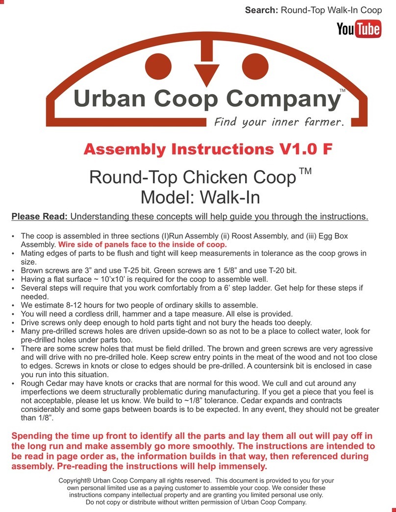
Urban Coop Company Round-Top Walk-In User manual

Urban Coop Company

Urban Coop Company Round-Top Walk-In User manual

Urban Coop Company Backyard Chicken Coop User manual

Urban Coop Company

Urban Coop Company Backyard Chicken Coop User manual

Urban Coop Company Round-Top Sustain Coop User manual

Urban Coop Company

Urban Coop Company Round-Top Sustain Coop User manual

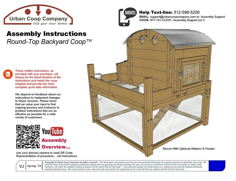
Urban Coop Company Round-Top Backyard Coop User manual

Urban Coop Company

Urban Coop Company Round-Top Backyard Coop User manual

Urban Coop Company Round-TopWalk-InCoop Harvey's Hen House User manual

Urban Coop Company

Urban Coop Company Round-TopWalk-InCoop Harvey's Hen House User manual

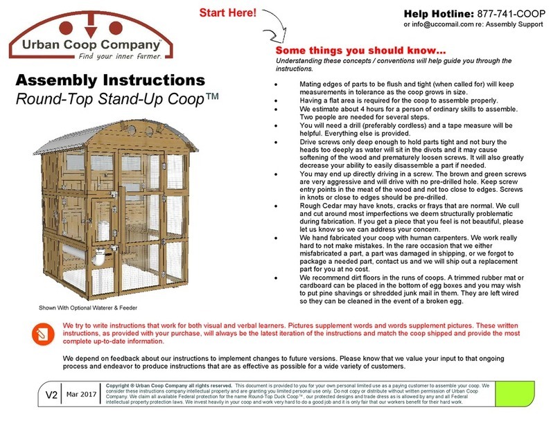
Urban Coop Company Round-Top Stand-Up Coop User manual

Urban Coop Company

Urban Coop Company Round-Top Stand-Up Coop User manual

Popular Farm Equipment manuals by other brands

VENCE TUDO CA-25 Especial Operation manual

VENCE TUDO

VENCE TUDO CA-25 Especial Operation manual

MacDon PW8 Operator's manual

MacDon

MacDon PW8 Operator's manual

Westar Udder Gun manual

Westar

Westar Udder Gun manual

Ziegler PKT 452 Original operating instructions

Ziegler

Ziegler PKT 452 Original operating instructions

Degelman R570P Operator's & parts manual

Degelman

Degelman R570P Operator's & parts manual

KUHN GF8702 Operator's manual

KUHN

KUHN GF8702 Operator's manual

Krone Big Pack 1270 Original operating instructions

Krone

Krone Big Pack 1270 Original operating instructions

Spectrum Technologies WatchDog Cellular Alert PRO product manual

Spectrum Technologies

Spectrum Technologies WatchDog Cellular Alert PRO product manual

APV AS 300 M1 operating manual

APV

APV AS 300 M1 operating manual

PRONAR ZKP690 Operator's manual

PRONAR

PRONAR ZKP690 Operator's manual

Waikato MK5 Technical manual

Waikato

Waikato MK5 Technical manual

Anderson RB-400 Operator's manual

Anderson

Anderson RB-400 Operator's manual

dosatron D 20 S owner's manual

dosatron

dosatron D 20 S owner's manual

New Leader NL5060 G5 Operator's & parts manual

New Leader

New Leader NL5060 G5 Operator's & parts manual

Maschio GIRAFFA 160 Use and maintenance / spare parts

Maschio

Maschio GIRAFFA 160 Use and maintenance / spare parts

sitrex BR 2030/6 Operator's manual

sitrex

sitrex BR 2030/6 Operator's manual

AGCO Gleaner 3200 Series Workshop service manual

AGCO

AGCO Gleaner 3200 Series Workshop service manual

Anderson TRB-2000 Operator's manual

Anderson

Anderson TRB-2000 Operator's manual

manuals.online logo
manuals.online logoBrands
  • About & Mission
  • Contact us
  • Privacy Policy
  • Terms and Conditions

Copyright 2025 Manuals.Online. All Rights Reserved.