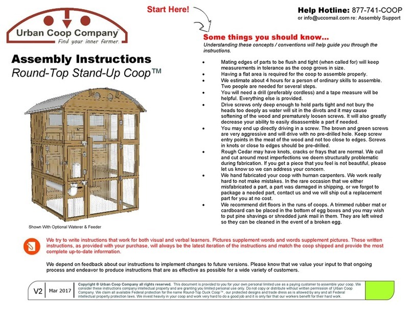
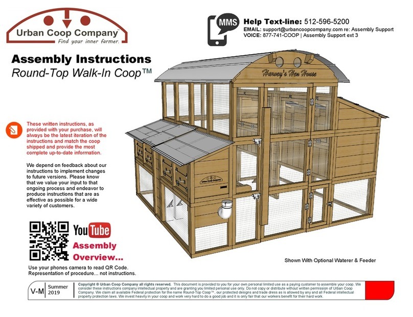
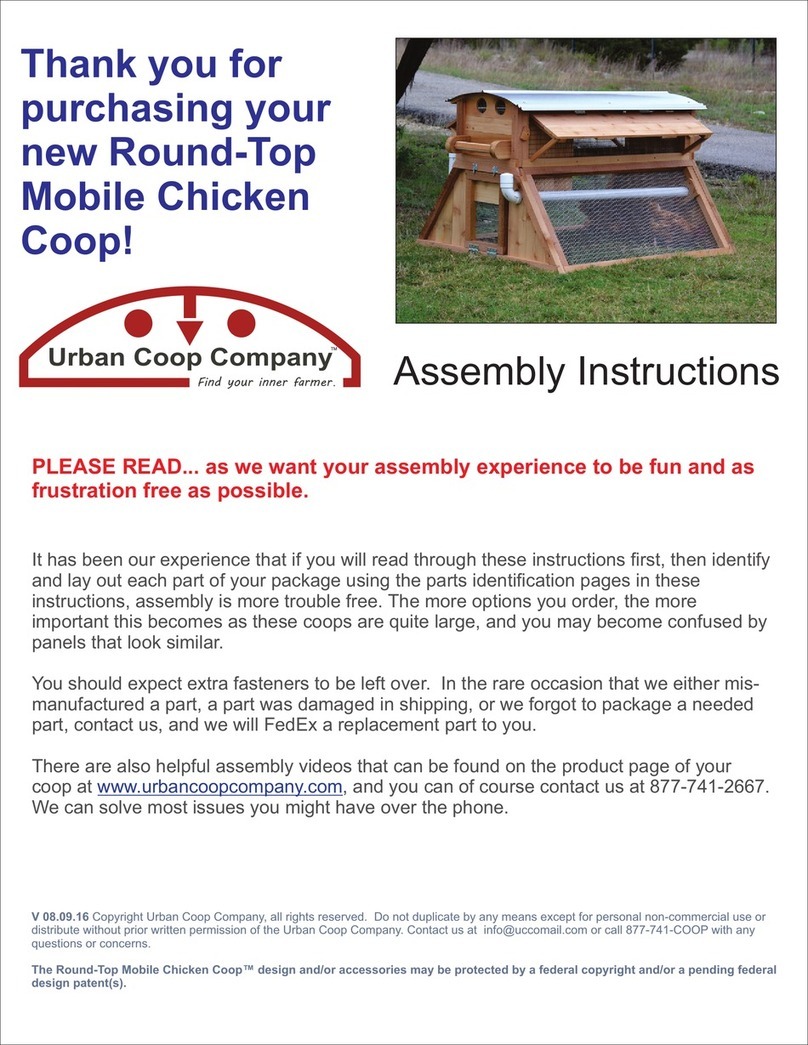
Urban Coop Company Round-Top Walk-In User manual

Copyright® Urban Coop Company all rights reserved. This document is provided to you for your own personal limited use as a paying customer to assemble your coop. We consider these instructions company intellectual property and are granting you limited personal use only.Do not copy or distribute without written permission of Urban Coop Company.
Urban Coop Company
TMFind your inner farmer TMRound-Top Chicken CoopModel: Walk-InAssembly Instructions V1.0 FPlease Read: Understanding these concepts will help guide you through the instructions.ŸThe coop is assembled in three sections (I)Run Assembly (ii) Roost Assembly, and (iii) Egg Box Assembly. Wire side of panels face to the inside of coop.ŸMating edges of parts to be flush and tight will keep measurements in tolerance as the coop grows in size.ŸBrown screws are 3” and use T-25 bit. Green screws are 1 5/8” and use T-20 bit.ŸHaving a flat surface ~ 10’x10’ is required for the coop to assemble well.ŸSeveral steps will require that you work comfortably from a 6’ step ladder. Get help for these steps if needed.ŸWe estimate 8-12 hours for two people of ordinary skills to assemble.ŸYou will need a cordless drill, hammer and a tape measure. All else is provided.ŸDrive screws only deep enough to hold parts tight and not bury the heads too deeply.ŸMany pre-drilled screws holes are driven upside-down so as not to be a place to collect water, look for pre-drilled holes under parts too.ŸThere are some screw holes that must be field drilled. The brown and green screws are very agressive and will drive with no pre-drilled hole. Keep screw entry points in the meat of the wood and not too close to edges. Screws in knots or close to edges should be pre-drilled. A countersink bit is enclosed in case you run into this situation.ŸRough Cedar may have knots or cracks that are normal for this wood. We cull and cut around any imperfections we deem structurally problematic during manufacturing. If you get a piece that you feel is not acceptable, please let us know. We build to ~1/8” tolerance. Cedar expands and contracts considerably and some gaps between boards is to be expected. In any event, they should not be greater than 1/8”.Spending the time up front to identify all the parts and lay them all out will pay off in the long run and make assembly go more smoothly. The instructions are intended to be read in page order as, the information builds in that way, then referenced during assembly. Pre-reading the instructions will help immensely.Search: Round-Top Walk-In Coop

110"
99 1/2"
20"58"32"
Egg Box AreaRun UnderRoost AreaRun Under
Stand Up RunAreaFront Door(Could Be On Other Side)Foot PrintRound-Top Walk-In CoopCopyright ® All Rights Reserved
Urban Coop Company
TMFind your inner farmer
FBCGRecommended NorthF=Egg Box Outside WallB= Run Egg Box Side WallC=Run Roost Side WallG=Roost Outside WallTMüRun, built first.Roost, built second.Egg Box, built last.3 Sub AssembliesNote: Door can be assembled on either end to change which side the roost or egg box side falls on. The only thing that changes in the design if you move the door to the other side is that the Waterer fill is then on the back of the coop.WaterFill

Parts Identification

Section 1- Run Assembly Parts List(1 of 4 Looking at Outside Face)A. Run Assembly Front¨ A1 X3 Front Door Panels¨ A2 X2 Run Lower Side Styles¨ A3 X2 Run Upper Side Styles¨ A4 Nameboard Arc¨ A5 Entry Door Handle (Stiffener)D. Run Assembly Back Side¨ D1 X3 Wired Back Panels¨ D2 Back Roof ArcRun Front & Back Parts ListRound-Top Walk-In CoopCopyright ® All Rights Reserved
Urban Coop Company
TMFind your inner farmerTMüDoorRound-Top Walkin Chicken CoopA1 MidA1 BottomA1 TopA2-LA2-RA3-LA3-RA4Run Assembly FrontRun Assembly BackD2D1 MidD1 LowerD1 Upper±±±±±±±A5 Door HandleHoleHoleHole in side towards top

Section 1- Run Assembly Parts List (2 of 4 Looking at Inside Face)B. Run Assembly Egg Box Side¨ B1 X4 Upper Wire Panels¨ B2 X2 Egg Box Door Assemblies¨ B3 Mid Section Support Strut¨ B4 X2 Octagonal Jump Bars¨ B5 X4 Jump Bar Brackets¨ B6 Metal Drip FlashingRun Egg Box Side Parts ListRound-Top Walk-In CoopCopyright ® All Rights Reserved
Urban Coop Company
TMFind your inner farmerTMüRun Egg Box Side Wall(looking from inside)B1-LB1-MLB1-MRB1-RB2-LB2-RB3B4B4B5.1B5.2 B5.3B5.4BB6 Drip FlashingProfile

Section 1- Run Assembly Parts List (3 of 4 Looking at Insode Face)C. Run Assembly Roost Side¨ C1 X2 Wood Lower Apron Boards ¨ C2 X2 Roost Access Door Assemblies¨ C3 X2 Wire Upper Transom Vent Panels¨ C4 Mid Section Support Strut Lower¨ C5 Mid Section Support Strut UpperRun Roost Side Parts ListRound-Top Walk-In CoopCopyright ® All Rights Reserved
Urban Coop Company
TMFind your inner farmerTMüRun Roost Side Wall(looking from inside)C1-LC1-RC2-LC2-RC3-LC3-RC4C5C

Section 1- Run Assembly Parts List (4 of 4)E. Run Assembly Roof Structure¨ E1Mid Roof Arc¨ E2 Mid Roof Suports X4¨ E3 Eave Boards X6 (4 with magnets)¨ E4 Mid-Roof Arc Support Brackets X2¨ E5 Run Roof Panels 107” X3Run Roof Parts ListRound-Top Walk-In CoopCopyright ® All Rights Reserved
Urban Coop Company
TMFind your inner farmerTMüE1 Mid Arc4X E2 Roof Supports34 7/8"Run Eave Boards x6 40° Bevel TopMagnets In 4 Outer Upper Eavesto Help Hold Roof In PlaceDuring Assembly.*6X E3 Eave Boards3X E5 Galvalume Roof Panels 107”2X E4 Mid ArcSupport Brackets

Section 2 - Roost Assembly Parts List(Looking at Outside Face)G. Roost Area Sub Assembly¨ G1 X2 Wired Side Bottoms¨ G2 X2 Wood Sloped Sides¨ G3 X2 Wood Side Mid Panels¨ G4 X4 Roost Bars¨ G5 X3 Ramps (2 short 1 long)¨ G6 Roost Ramp Landing¨ G7 X2 Roost Ramp Supports¨ G8 Mid Roost Bar Support¨ G9 X2 Wired Lower Panels¨ G10 X4 Wood Roost Backs¨ G11 X3 Eave Boards¨ G12 X3 Roof Supports¨ G13 X3 Roof Support Brackets¨ G14 X1 Mid Roost Bar Support Bracket¨ G15 Roost Roof Panels 103” X 2 Roost Parts ListRound-Top Walk-In CoopCopyright ® All Rights Reserved
Urban Coop Company
TMFind your inner farmerTMü G7 2X Roost Ramp SupportsG8 Mid-Roost Bar SupportG4 4X Roost BarsG15 2X Galvalume Roof Panels 103”(one has edge cut off)G5 RampsG6 Roost Ramp LandingG13 Roof Support Brackets X3G14 Mid Roost Bar Support BracketG12 3x Roof SupportsG11 X3 Eave BoardsG10-LG10-MLG10-MRG10-RG1 2XG3 2XG2 2XG9 LG9 R

Section 3 - Egg Box Assembly Parts List(Looking at Outside Face)F. Egg Box Sub Assembly¨ F1 X2 Wired Side Bottoms (1x water cutout)¨ F2 X2 Wood Sloped Side Tops (1x Logo)¨ F3 X4 Feeder Tubes¨ F4 X2 Waterer Sections¨ F5 X2 Waterer Hanger Brackets¨ F6 X2 Outer Egg Box Dividers¨ F7 X2 Inner Egg Box Dividers (Magnets)¨ F8 X2 Wire Egg Box Bottom Panels¨ F9 X2 Feeder Holster Brackets¨ F10 X2 Egg Collection Door Assemblies¨ F11 X2 Wired Lower Eggbox Panels¨ F12 Egg Box Mid Panel¨ F13 X2 Eave Boards Outer¨ F14 X1 Eave Boards Middle (magnet)¨ F15 X2 Egg Box Roof Metal¨ F16 X1 Feed Compartment Roof MetalEgg Box Parts ListRound-Top Walk-In CoopCopyright ® All Rights Reserved
Urban Coop Company
TMFind your inner farmerTMüF6 OutterEgg BoxDividers X2(Mirrored)F7 InnerEgg BoxDividers X2(Mirrored w/mangnets)Egg Box DividersRound-Top Chicken Coop
x2x2F3F15 2X GalvalumeF16 GalvalumeF4 Waterer SectionsF1F1F2 x2F5 x2F9 x2F10-LF10-RF11-LF11-RF12F13 x2F14F8 x2

Tool Kit & Loose PartsH. Tools & Loose Parts¨ H1 Small can PVC Glue¨ H2 Gold T-25 6” Screws #12¨ H3 Brown T-25 3” Screws ~300¨ H4 Green T-20 1 5/8” Screws ~75¨ H5 Bolt Style Gate Latch¨ H6 Locking Clip¨ H7 Door Handles X5 (if not attached)¨ H8 Eye Bolt & Hooks X5¨ H9 Poultry Nipples X4¨ H10 #100 Neoprene Washer Roof Screws¨ H11 3” Door Hinges X4 & 24+ #8 1 1/2” Screws¨ H12 Bit Holder¨ H13 T-25 Bit¨ H14 T-20 Bit¨ H15 #2 Phillips Bit¨ H16 Window Bolts X8 (if not attached)¨ H17 12” Stake Nails X2¨ H18 2’ Level¨ H19 Countersink Bit¨ H20 2X Roost Access Door Fowl Weather Panels¨ H21 ~ #10 Brad Nails¨ H22 ~ 10 Feet of String¨ H23 ~ 12 5/8 Phillips Screws for RampsLoose Parts ListRound-Top Walk-In CoopCopyright ® All Rights Reserved
Urban Coop Company
TMFind your inner farmerTMü

Section 1Run Assembly

Step 1.1 Lower Run Egg Box WallRound-Top Walk-In CoopCopyright ® All Rights Reserved
Urban Coop Company
TMFind your inner farmerTM
B2 LB2 RB3ŒUsing the brown T25 screws, screw the upper rail of D1 Lower up into the bottom rail of D1 Mid concealing the screws on the underside of the parts. Make sure all edges are flush. Use at least four screws, two in each section, to join parts. Attach B2L and B2R to B3 making top edges flush (screw holes may be behind doors) and using at least two screws on each side. Ž Screw the Run Lower Egg Box Run Wall Assembly (B) onto the Lower Run Back Wall Assembly (D) using two brown T-25 screws keeping edges flush and the (D) wall overlapping the outside edge of the (B) wall. See Figure ŒScrew panel lower front door side panel A2L onto B2L using two brown T-25 screws driving them from inside B2L door frame into frame of A2L with tops and sides flush. See Fig Œ
B. Run Egg Box Side Lower Wall Assembly
D. Run Back WallLower Assembly
Standing Inside Run Looking at Egg Box WallAll Wire Faces InFigŒB Side Wall PanelsA & D End WallsOverlapOpen Doors AndDrive Screws InsideFrameD1 MidD1 LowerNote: Bend or CutWire On End PanelIf Opening DoorBolt Hits Wire AfterAssembly.

Step 1.2 Lower Run Roost WallRound-Top Walk-In CoopCopyright ® All Rights Reserved
Urban Coop Company
TMFind your inner farmerTM
ŒUsing the brown T25 screws, screw the upper rail of CL1 Apron Panel C2L Roost Access Door Assembly concealing the screws on the underside of the parts. Make sure all edges are flush. Use at least three screws to join parts.Repeat procedure in step 1 for the C1R and C2R panels.Ž Screw C5 to top of C4 making flush on all edges. Pre-Installed brackets on the C4 C5 strut are on back side.Attach the C1/C2 Left assembly to the C4/C5 Strut assembly making top edges flush. Repeat for the C1/C2 Right side too.Attach rear lower D Run Back Wall Assembly to the C Run Roost Wall lower assembly making sure bottom edges of C1 are flush with the seam of the two back D panels and the D wall assembly mates flush on the outside of the C wall assembly.‘Attach A2R side door panel onto front outer edge of the C Wall Assembly where bottom of C1R is 25” from bottom of A2R.*B Egg Box Run Wall AssemblyIn Prior Step Omitted
D Run Lower Back Wall Assembly
C Run Lower Roost Wall Assembly
Lines up. Bottomof C1 is 25” offbottom of lower D panel.
25 inches
Standing Inside Run Looking at Roost WallWire Faces In...

Please Be CarefulŒ Some of the next steps will need to be performed from a six foot or taller step ladder. If you are not comfortable and experienced standing on and working from a ladder you may want to get some help for these steps. Please be careful. Any roof metal can have sharp edges. We attempt to knock of sharp corners and edges from roof metal. You must be the final determiner of sharp edges. A standard metal file from your hardware store, or metal snips, can be used to make edges to your standards. You may choose to wear a pair of work gloves while handling roof metal.

Step 1.3 Upper Run Egg Box SideRound-Top Walk-In CoopCopyright ® All Rights Reserved
Urban Coop Company
TMFind your inner farmerTM
ŒUsing provided brad nails, attach drip flashing strip along the top edge of the lower B wall egg box sub assembly built in previous step, centering to middle and leaving gaps on ends. See figure 2.1.A.Using T-25 brown screws attach upper D1 panel onto lower back panels assembled in previous step. Use at least 4 screws, 2 in each section.ŽUsing T25 brown screws, attach the 4 B1 panels, sandwiching the B6 flashing, on top of the B2 egg box door and B3 Mid Strut assembly assemble in prior steps. Use at least 2 screws per panel. Beveled upper edges of B1 panels will be slanting down and out.Use at least two of the T25 brown screws per panel to attach the sides of each of the four B1 panels to each other.Using T25 brown screws attach A3L to the top of the A2L panel screwing both into A2L and into ends of B1R.‘Make sure back side D1 Upper panel is also screwd into B1L panel too.Note: B1 panels will stick up a little beyond tops of front and back.B6 ProfileWoodBradFig2.1.ABeveled Edge SlantsDown And OutwardTop Edge Will Stick Above EndsStanding Outside Run Looking at Egg Box WallBB6 Flashing When CenteredWill Be Short by 1 3/4”On Each End.Wire Faces In...

Step 1.4 Upper Run Roost SideRound-Top Walk-In CoopCopyright ® All Rights Reserved
Urban Coop Company
TMFind your inner farmerTM
ŒUsing Brown T-25 screws attach C3 panels to the tops of C2 panels and C5 strut panel making sure edges are flush and that beveled top edge slopes down and out. Open C2 doors and drive screws up into C3 parts, at least 3 screws per side. Make sure to get at least 1 screw from each panel into C5 strut top.Note: There may be a Brown T-25 screw holding the C2 doors shut for shipping.Drive T25 screws from lower A2R panel up into bottom of A3R panel and then screws from sides of A3R into frames of C2R and C3R.ŽRepeat procedure in step for upper D1 panel and the C2L and C3L panels. Standing Outside Run Looking at Roost WallBeveled edge slopes down and outC Side Sticks up a little from A Front and D BackC

Step 1.5 Run Roof FrameRound-Top Walk-In CoopCopyright ® All Rights Reserved
Urban Coop Company
TMFind your inner farmerTM
ŒUsing 6 T25 screws, attach A4 to the top of the Run Assembly Front “A” Wall that is assembled so far making flush the ends of the A4 top and the A3 sides. Use 3 screws on each side. When the sides are flush, the door frame opening will be correct. Screws can either be driven up from top rail of A3 parts into bottom rail of A4 or from lip on A4 rail down into tops of A3 parts.Repeat the above process for the Run Assembly Back “D” Wall using at least 6 of the T-25 screws to attach D2 to the top of the D1 panels.ŽInstall the Mid Arc Support Brackets E4 using T-25 Brown screws onto the top center B1 Wall Assembly centering the fork of the bracket on the center seam and making the top of the bracket flush with the top of the beveled edge. E4 bracket is used to E1 position mid arc.Repeat same procedure on opposite C3 Roost Side Wall Top Panels. Run Assembly Front “A” WallRun Assembly Back “D” WallA3LA3RRound-Top Walkin Chicken CoopA4D2E4ŽCenter of B1 Egg Box Run SideWall AssemblyCenter of C3 Roost Run SideWall AssemblyE4

58"Stand Up RunAreaFront Door(Could Be On Other Side)Step 1.6 Foot Print SquaringRound-Top Walk-In CoopCopyright ® All Rights Reserved
Urban Coop Company
TMFind your inner farmer
FBBCCRecommended NorthAerial View Of What You Should Have Assembled So Far... Run Egg Box Side Wall Run Roost Side WallTMü
99 1/2"
Drive 12” Stakes IntoGround After SquaringRun & Making SureDoor Opening Is 27 1/2 Inches Inside Opening=ŒObserve drawing and make sure that what you have done so far matches up to illustration, 58” wide and 99 1/2” long, off no more than 1/4”.Next, using a measuring tape, measure the diagonals of the lower run until each corner-to-corner measurement is equal. Hold tape level each time and pull taught. Rack as needed to make 90° corners which will happen when corner to corner is equal.ŽUsing provided level, check all sides placing the level in different spots and level the coop in all directions vertical and horizontal and make sure that it is not rocking. Some settling will occur and it is okay, but this is the time to get it the best you can.Referencing the footprint at the front of these instructions, position the coop on your site area where you want it as this portion won’t be moved again. Recommended North is based on the Roost being Protected from wind.Finally, see note in illustration and make sure mid section long walls and front wall is straight by moving back and forth until wall is straight along string, just touching it.‘Make sure the A2 Lower Front Panels have 27 1/2” between them up and down and then using a hammer, drive the 12” provided stakes down through the holes in A2 bottoms into ground so as to keep door frame properly separated. Make sure corners are square.27 1/2"A2LA2RD Back Run WallPull string taught along both long sides and front and make sure walls are straight. Push or pull in or out as required.90°90°90°90°Critical Step!

Step 1.7 Run Roof FrameRound-Top Walk-In CoopCopyright ® All Rights Reserved
Urban Coop Company
TMFind your inner farmerTM
ŒInsert E1 Mid Arc into E4 support brackets that were installed in prior step. Using H2 Gold T-25 5” long screws, drive two screws in each outter run wall B & C such that the screws drive through the B1 & C3 upper panels and into the laminated end of the E1 mid arc. Screws will be driven at an angle and should drive into the middle of E1 in an upper and lower pattern. See Fig ŒInsert front end set of E2 Roof supports so that the notched corbel ends stick out beyond A4 Front Arc and the square back ends fit into pockets on E1 Mid Support. Fit will vary but should be snug. Drive 1 T25 Brown screw from inside of back side of E1 pockets so the screw drives through E1 and into E2 ends. See Fig ŽRepeat process in step for back set of E2 Roof Supports that hook into D2 Back Arc. Secure back side of this set of Roof Supports by toe screwing a Brown T25 screw at an angle from the back side of E1 Mid Arc so that the screw drives into E2 holding it secure to E1. Fig Note: These screws are mainly used to hold the roof into place while the eaves and metal are installed which will do most of the work to keep the roof attached. So make it look pretty, and know that the work of keeping things strong happen in next steps.4X E2 Roof SupportsE4 BracketE1 Mid-ArcFig ŒSee-Thru ViewLooking Outside to InsideEnd ViewE1 Mid ArcE4 BracketBeveled Top Edge of RunSide WallsGold T25Long ScrewsWalls Of Run Built So FarAre Omitted For SimplicityFig FirstScrew2ndScrewE2E2E1

Step 1.8 Run Roof EavesRound-Top Walk-In CoopCopyright ® All Rights Reserved
Urban Coop Company
TMFind your inner farmerTM
ŒUsing green T20 screws in the pre-drilled holes, attach the 6 E3 eave boards, 3 each side to the top side walls B&C of the run assembly. First install middle eave board, centering it on the E1 mid arc, then install outer eave boards which have magnets, facing magnets up. Back of eave boards should run flush along upper beveled 2x4 of B&C walls and top face of eaves should fit substantially flush along the top edges of all three arcs giving a smooth surface for the roof metal to roll onto. Adjust the board angles as needed to make transition as smooth as possible while screwing down.Repeat procedure for both run sides. All boards are equal length. Just the orientation of the magnet is the difference.Walls Of Run Built So FarAre Omitted For SimplicityE3 1x6 Eave Boards(middle board no magnet)Magnets are embeddedin outer 4 eave boards(2 each side) to help youhold the roof metal in placeduring installation.Beveled EdgeOn TopMagnet
This manual suits for next models
1
Table of contents
Other Urban Coop Company Farm Equipment manuals

Urban Coop Company
Urban Coop Company Backyard Chicken Coop User manual

Urban Coop Company
Urban Coop Company Round-Top Stand-Up Coop User manual

Urban Coop Company
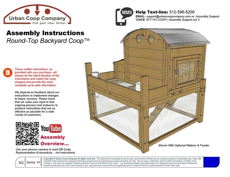
Urban Coop Company Round-Top Backyard Coop User manual

Urban Coop Company
Urban Coop Company Round-Top Sustain Coop User manual

Urban Coop Company
Urban Coop Company Round-TopWalk-InCoop Harvey's Hen House User manual

Urban Coop Company
Urban Coop Company Round-Top Mobile Chicken Coop User manual