urmet domus UFO 12M User manual

DS1099-168
Mod.
1099
IP H.265+ Fish Eye Camera
UFO 12M Ref. 1099/680
USER MANUAL

2
DS1099-168
LIST OF CONTENTS
1Introduction................................................................................................................................................4
2Product Description ..................................................................................................................................5
2.1 Technical features .....................................................................................................................5
2.2 Opening the Box........................................................................................................................6
2.3 Warnings ...................................................................................................................................6
3Overview.....................................................................................................................................................8
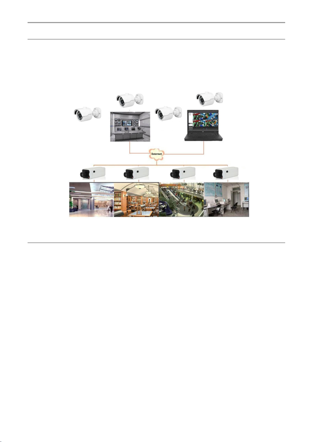
3.1 Range of Application .................................................................................................................8
3.2 Product description....................................................................................................................8
3.3 Operating environment..............................................................................................................9
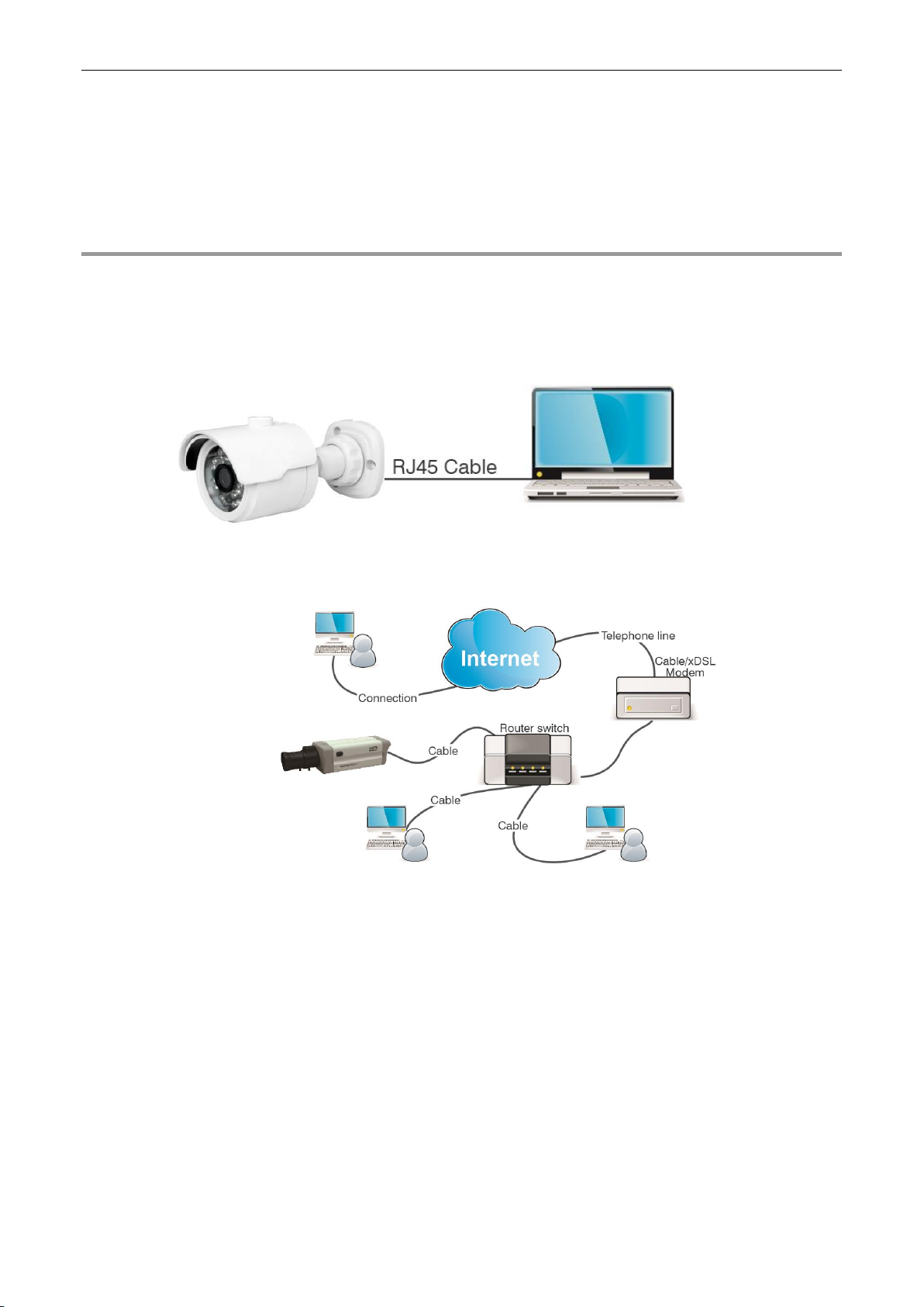
4Device Connection ....................................................................................................................................9
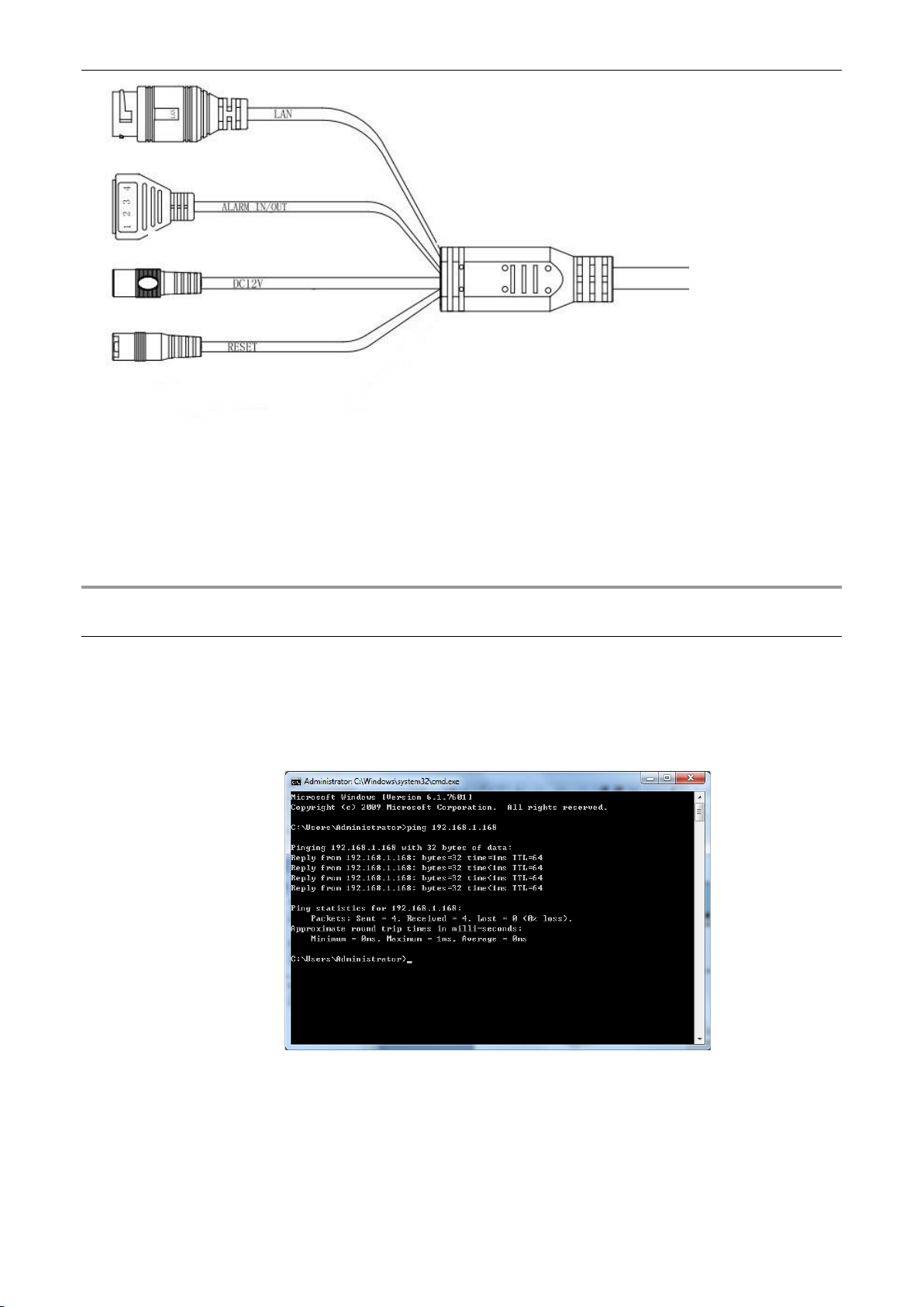
4.1 IP Camera Connector Layout (Where Present) ..................................................................... 10
5Operating instructions........................................................................................................................... 10
5.1 Connection Check .................................................................................................................. 10
5.2 Device Searching ................................................................................................................... 11
5.3 Installation of Controls and Login to System.......................................................................... 12
6Login........................................................................................................................................................ 12
7Preview.................................................................................................................................................... 13
8Live .......................................................................................................................................................... 14
8.1 Fish Eye functions (Live and Playback) ................................................................................. 15
8.1.1 Types of installation ....................................................................................................................................15
8.1.2 Display........................................................................................................................................................15
8.1.3 Ceiling installation.......................................................................................................................................15
8.1.4 Wall installation...........................................................................................................................................21
8.1.5 Installation on a horizontal surface..............................................................................................................24
8.1.6 Installation on an inclined plane..................................................................................................................30
9Local settings ......................................................................................................................................... 34
10 Playback.................................................................................................................................................. 35
11 Remote Setting ....................................................................................................................................... 37
11.1 Display Configuration ............................................................................................................. 37
11.1.1 Live.............................................................................................................................................................37
11.1.2 Image Control .............................................................................................................................................38
11.1.3 video Cover (Privacy Zone).........................................................................................................................39
11.1.4 ROI .............................................................................................................................................................39
11.2 Record Parameters ................................................................................................................ 40
11.2.1 Encode........................................................................................................................................................40
11.2.2 Record........................................................................................................................................................41
11.2.2.1 Schedule..................................................................................................................................................41
11.2.3 Capture.......................................................................................................................................................41
11.3 Event....................................................................................................................................... 42
11.3.1 Setup ..........................................................................................................................................................42
11.3.1.1 Motion......................................................................................................................................................42
11.3.1.2 Siren........................................................................................................................................................43
11.3.1.3 Sound Detection ......................................................................................................................................43
11.3.2 Alarm ..........................................................................................................................................................44
11.3.2.1 Motion......................................................................................................................................................44
11.3.2.2 I/O............................................................................................................................................................45
11.3.2.3 Sound Detection ......................................................................................................................................46
11.3.3 Event Push .................................................................................................................................................47
11.4 Network .................................................................................................................................. 47
11.4.1 General.......................................................................................................................................................47
11.4.1.1 General....................................................................................................................................................47
11.4.1.2 PPPoE.....................................................................................................................................................48
11.4.1.3 SNMP......................................................................................................................................................49
11.4.1.4 Port Configuration....................................................................................................................................49
11.4.2 E-Mail Configuration ...................................................................................................................................50
11.4.3 FTP.............................................................................................................................................................51
11.4.4 RTSP..........................................................................................................................................................51
11.4.5 DDNS Configuration ...................................................................................................................................51
11.4.6 HTTPS........................................................................................................................................................52
11.4.7 IP Filter .......................................................................................................................................................52
11.5 Device..................................................................................................................................... 53
ENGLISH

3
DS1099-168
11.5.1 Disk.............................................................................................................................................................53
11.5.2 Audio...........................................................................................................................................................54
11.5.3 Cloud ..........................................................................................................................................................55
11.6 System.................................................................................................................................... 56
11.6.1 General.......................................................................................................................................................56
11.6.2 User Configuration......................................................................................................................................57
11.6.3 Maintenance...............................................................................................................................................57
11.6.3.1 Log ..........................................................................................................................................................57
11.6.3.2 Load Default ............................................................................................................................................58
11.6.3.3 Upgrade...................................................................................................................................................58
11.6.3.4 Parameter Management ..........................................................................................................................58
11.6.3.5 Auto Reboot.............................................................................................................................................59
11.6.4 System Information.....................................................................................................................................59
12 Fisheye IP Camera Technical Specifications ...................................................................................... 60
13 Maximum recording time with SD Card ............................................................................................... 62
13.1 Ref. 1099/680......................................................................................................................... 62
14 Appendix ................................................................................................................................................. 63
14.1 Router Port Forwarding.......................................................................................................... 63
14.2 Frequently Asked Questions .................................................................................................. 64

4
DS1099-168
1 INTRODUCTION
Thank you for purchasing our integrated and developed network camera products for network video monitoring. Our range
includes the following products: Storage Network Bullet, Wireless Storage Network Bullet, IR Network Dome, IR Network
Weather-Proof and High-Speed Network Ball, fisheye cameras. High-performance single SOC chips are used in the media
processor for audio/video acquisition, compression and transmission/transfer. A standard H.265 encoding algorithm is
applied to ensure clear and smooth video representation and high transfer performance. The integrated Web Server allows
users to access real-time surveillance and remote control of the front-end camera via any Internet browser, although some
specific commands are only available using the Edge browser running in Internet Explorer mode.
The network cameras are easy to install and operate. They are ideal for large and medium-sized companies, governmental
projects, large malls, supermarket chains, intelligent buildings, hotels, hospitals, schools and other public places, as well as
for applications requiring remote network video transmission and monitoring.
Instructions:
➢For the purposes of this manual, an IP camera refers to a network camera.
➢The default factory IP address for the IP camera is 192.168.1.168.
➢The default factory administrator username for the IP camera is admin (in lowercase) and the password to set during
the first login in following the rules for compilation.
➢The default Web port number is 80 and the client port number is 9000.
Statement:
Some information contained in this manual may differ from the actual product. For any problems that cannot be solved
with the help of this manual, please contact our technical support or an authorised dealer. This manual may be subject to
change without prior notice.

5
DS1099-168
2 PRODUCT DESCRIPTION
URMET S.p.A Ref. 1099/680 is 12MegaPixel IP camera that can be controlled via a TCP/IP network connection.
2.1 TECHNICAL FEATURES
➢High-performance Sigma Star media processor with advanced functions.
➢CMOS Progressive Sensor
➢Optimized H.265+/H.265/H.264+/H.264 video compression algorithms; multi-stream transmission ensures high
definition image transmission on both narrowband and wideband.
➢Support simultaneous connection of up to 9 users. There are 23 video streams available.
➢SD Card support up to 256GB (for Fishe Eye UFO camera models). The integrated Web Server allows multi-
browser use (Edge, Firefox Mozilla up to version 51 and Safari 6.0 for MAC O.S., Google Chrome) for real-time
on-site monitoring, setup and management. Some specific commands are only available using the Edge browser
running in Internet Explorer mode.
➢Managed from Urmet UVS pro Client Software
➢Mobile software for the following platforms: iOS (iPhone and iPad), Android (smartphones and tablets).
➢Remote system firmware updates.
➢Support LAN and Internet.
➢Support ONVIF and RTSP protocols.
➢Support multiple network protocols, such as TCP/IP, UDP, ICMP, HTTP, HTTPS, FTP, DHCP, DNS, DDNS, RTP,
RTSP, PPPoE, NTP, UPnP, SMTP, SNMP, IGMP, IPv6.
➢Support motion detection alarm function (the user can set the area and sensitivity) and sensor/alarm out function
(for Fishe Eye UFO camera models). Support privacy zone function.
➢POE power supply function.
➢Support snapshot. Image upload via FTP or E-mail.
➢Log Support: System logs, Configuration logs, network logs, alarm logs, account logs, record logs, storage logs
and all logs
➢Reset Button supported (where included)
➢Support automatic download recovery function. Automatic connection in the event of network interruption.
Note: The specifications of different products may change slightly.

6
DS1099-168
2.2 OPENING THE BOX
Check that the packaging and the contents are not visibly damaged. Contact the retailer immediately if parts are either
missing or damaged. Do not attempt to use the device in this case. Send the product back in its original packaging if
damaged.
ACCESSORIES PROVIDED
➢1 IP camera unit
➢1 installation bag
➢1 Wall/ceiling mounting plate
➢1 Quick Guide
➢1 Addendum OSS Notice in paper format
IMPORTANT NOTE:
Accessories may be changed without prior notice.
2.3 WARNINGS
Power supply
➢Before connecting the equipment to the electrical outlet, ensure that the nameplate specifications match those
of the mains power supply.
➢It is advisable to install a suitable disconnection and protection switch upstream from the equipment.
➢In the event of failure or malfunction, disconnect the power supply at the main switch.
Safety precautions
➢Keep the device away from rain and dampness to prevent the risk of fire and electrocution. Do not introduce
any material (solid or liquid) inside it. If this should accidentally occur, disconnect the device from the mains
and have it inspected by qualified personnel.
➢Never open the device. In all cases, contact qualified personnel or an authorised service centre for repairs.
➢Keep the device away from children, to prevent accidental damage.
➢Do not touch the device with wet hands to prevent electrical shock or mechanical damage.
➢Do not use the device if it falls or if the external casing is damaged. Continued use of the device in such
conditions could cause an electric shock. In such cases, contact the retailer or authorised installer.
Installation precautions
➢Do not install the camera in places exposed to rain or humidity. In these situations, use the special cases.
➢Avoid pointing the camera directly towards sunlight or other intense sources of light, even when switched off;
the subject to be filmed should not be against the light.
➢Avoid pointing the camera towards reflecting objects.
➢The presence of certain types of light (e.g. coloured fluorescent light) can distort the colours.
➢Do not position this device on an unstable surface, such as a tottering or slanted table. The device could fall,
causing injury or mechanical failures.
➢Stop using the device if wateror some other material penetrates inside it, to prevent risk of fire or electrocution.
In such cases, contact the retailer or authorised installer.
➢Do not cover the device with a cloth while it is running to prevent deformation of the external casing and
overheating of internal parts, causing risk of fire, electrocution and mechanical failure.
➢Keep magnets and magnetised objects away from the device to prevent faults.
➢Do not use the device in the presence of smoke, vapour, humidity, dust or intense vibrations.
➢Do not operate the device immediately after moving it from a cold place to a warm place and vice versa. Wait
on average for three hours: this will allow it to adapt to the new environment (temperature, humidity, etc. ).
Precautions for use
➢Check that the device is not damaged after removing it from the packaging.
➢Ensure that the working environment is not too humid and that the temperature is within the indicated range.
➢Avoid pointing the camera towards sunlight to prevent damage to the sensor.
Cleaning the device
➢Rub gently with a dry cloth to remove dust and dirt.
➢Dip the cloth in mild detergent if dirt cannot be removed with a dry cloth alone.
➢Do not use spray products to clean the device. Do not clean the device using volatile liquids (such as petrol,
alcohol, solvents, etc.) or chemically treated cloths to prevent deformation, deterioration or scratches to the
paint finish.
➢Disconnect the device from the electrical outlet before any cleaning or maintenance operations.
Recording images
➢This device is not designed as a burglar-control system but mainly to transmit and record images. URMET
S.p.A. may not be held liable for loss or damage caused by thefts from the user's premises.

7
DS1099-168
➢Make a test recording before using the device to ensure that is working correctly. Please note that URMET
S.p.A. is not liable for any loss of stored data or damage caused by incorrect installation, improper use or
malfunctioning of the device.
➢This device contains precision electronic components. Protect the device from bumps and jolts to ensure
proper recording of images.
Privacy and Copyright
➢The IP camera is designed for CCTV systems. The recording of images is subject to the laws in force in
the country of use. Recording of images protected by copyright is forbidden.
➢Product users are responsible for checking and complying with all local rules and regulations regarding
monitoring and the recording of video signals. The manufacturer SHALL NOT BE LIABLE for any use of
this product that is not in compliance with the laws currently in force. For more information please visit
http://www.garanteprivacy.it
Firmware/software upgrade
➢You are advised to refer periodically to URMET S.p.A. website in the product-specific section for software
and/or firmware updates (go to www.urmet.com in the "VIDEOSORVEGLIANZA AREA" product section,
type the reference product code in the search field and move to DOCUMENTATION AND RESOURCES).
Network configuration
➢The camera default setting is DHCP mode. If the installation network does not support dynamic addressing
(DHCP), the device will automatically switch to the factory-set IP address 192.168.1.168. Use Urmet's
“Device Config Tool” software to modify the factory IP address and other camera network settings to prevent
any conflict with other devices in the network.
➢Once the camera is properly connected and configured on the IP network, its video and settings can be
viewed from a PC or smartphone.
Network connections
➢When connecting a remote PC (using client software or a browser), it should be borne in mind that any
video channel used on the PC will have a “unicast” connection (TCP, RTP, UDP).
➢The device can support up to 9 “unicast” connections, i.e. the video stream can be viewed from a maximum
of 9 remote (PC or smartphone) devices at the same time, depending on the available bandwidth.

8
DS1099-168
3 OVERVIEW
3.1 RANGE OF APPLICATION
These network cameras with their powerful image processing capacity can be used in various public places, such as malls,
supermarkets, schools, factories and workshops, as well as in environments requiring HD images, such as banks and traffic
control systems, as illustrated in the figure below:
3.2 PRODUCT DESCRIPTION
An IP camera is an online digital surveillance camera, equipped with a web server and capable of independent operation,
providing the user with access to real-time monitoring from any location through a web browser or client software.
These IP cameras feature the most advanced Sigma Star solution: an integrated media processing platform for audio/video
capture, compression and network transmission on a single board. This is in compliance with H.264/H.265/H.264+/H.265+.
High Profile encoding standards. Remote users can have access to real-time monitoring by entering the IP address or
domain name of the IP camera in the web browser. This network camera solution is suitable for residential or business
environments, as well as a wide range of situations that require remote network video monitoring and transmission. The IP
cameras are easy to install and operate.
The IP cameras can be controlled by several users with different levels of authorisation.
IP cameras allow for mobile detection and sending of e-mail and snapshots in case of emergency; the videos or image
snapshots are then stored to the SD card for subsequent retrieval.
Monitoring centre

9
DS1099-168
3.3 OPERATING ENVIRONMENT
Operating system: Windows 7/Windows 8/Windows 2008 (32/64-bit), Windows 2003/Windows XP/Windows 2000 (32-bit)
or higher
CPU: Intel Core Duo II processor or higher
Memory: 1G or higher
Video memory: 256M or higher
Display: 1024 × 768 or higher resolution
4 DEVICE CONNECTION
The IP camera can be connected in two ways:
•Connection to a PC
Connect the IP camera to the PC using a direct network cable, with the power input connected to a 12VDC adaptor,
and enter the IP addresses of the PC and the camera in a network segment. The IP camera will communicate with
the PC within one minute after being switched on if the network is working properly.
•Connection to a router/switch
This solution is more commonly used in connecting the IP camera to Internet; in this case, the camera and PC are
connected to the LAN ports of a router/switch, with the camera gateway set to the IP address of the router.

10
DS1099-168
4.1 IP CAMERA CONNECTOR LAYOUT (WHERE PRESENT)
1. LAN (Network Interface): Connector for a RJ45 network cable.
2. ALARM IN/OUT: Including alarm input and output interface.
①, ② as input alarm interface setting, ③, ④ for output alarm setting
3. DC 12V: Power Interface
4. RESET: The device will restore the default settings if this button is pressed and held for 3 seconds.
5 OPERATING INSTRUCTIONS
5.1 CONNECTION CHECK
•The default factory IP address for the IP camera is 192.168.1.168 and the subnet mask is 255.255.255.0. Allocate to
your computer an IP address in the same network segment as the IP camera, for example, 192.168.1.69, and the
same subnet mask as that of the IP camera.
•Test whether the IP camera is connected properly and started normally by clicking on Start > Run and entering "cmd"
and then pressing ENTER, then enter "ping 192.168.1.168" in the command line window.
•Check whether the IP camera is accessible. If the PING command is run successfully, it means that the IP camera is
operating normally and the network is connected properly. If the PING command fails, check the IP address and
gateway settings of the PC, as well as the network connection.

11
DS1099-168
5.2 DEVICE SEARCHING
•Feedback: The Device Config Tool function can be used for device searching across network segments. Before using
Device Config Tool, click on the local connection icon in the bottom right corner of the desktop;
•Add IP addresses of several network segments in the TCP/IP setting for local connection (as shown below). You can
run this tool to search for any device with an IP address in the same network segment.
Note:
The Device Config Tool function uses the multicast protocol for device searching across segments; however, since any
firewall prevents traffic of multicast data packets, any firewalls must be disabled for information on the device to be acquired.
Online device search procedure
1. Launch the Device Config Tool by selecting (double-clicking) the icon .
The function will search and display any online device and its IP address, port number, web port number, number of
channels, configured name, device type and version, subnet mask, gateway, MAC address and connection pattern and
state.

12
DS1099-168
5.3 INSTALLATION OF CONTROLS AND LOGIN TO SYSTEM
Before using the IE (Internet Explorer) browser to access the IP camera for the first time, the plug-in components must first
be installed, as follows:
Access the IP address of the IP camera to automatically download the controls from it.
Select an option in the plug-in installation pop-up dialogue box to run the installation process.
6 LOGIN
Open a Browser (all browsers for managing camera parameters from page [without video] or Edge in IE mode for complete
camera management [parameters and video]) and enter the IP address of the camera (http://192.168.1.168), the window
for creating the Administrator password will open: you must set the password immediately to safeguard your privacy; the
password must contain a combination of 8 to 16 characters. Write down the password and keep it in a safe place.
Confirm with OK
A window will now appear where the user can choose and configure how to retrieve the password in the event of its loss.
➢Security Question Configuration: choose one of the proposed questions and fill in the corresponding answer (enabling
this function requires all security questions to be filled in); if the password is lost, it will be possible to set a new password

13
DS1099-168
using the password recovery function
➢Certificate of authorisation: it will be possible to export a certificate (to be noted down and kept in a safe place), which
in the event of loss of the password, can be used to set it again using the password recovery function
➢Super code: by enabling this function, it will be possible to contact Urmet Customer Service to request a SUPER CODE
that will allow you to set a new password using the password recovery function.
Once the options have been selected, confirm with OK
At the end of the password change process, the following window will appear:
Confirm with the OK button.
NOTE: If no password recovery method is chosen, in the event of a lost password, it will be necessary to act directly on the
RESET button (located on one of the camera's cables), thus returning the camera to its factory settings.
7 PREVIEW
Open Edge in IE mode and enter the camera's IP address (http://192.168.1.168) to display the login window below:
Login interface for Fish Eye IP cameras.
In the login window you can choose a language. Enter your username (admin by default) and password (previously set) and
then press Login.

14
DS1099-168
8 LIVE
Some of the buttons in the preview frame are described below.
: Button for setting the hue, brightness, contrast, saturation and sharpness of the frame.
: Reads the recording file from the SD card and plays it back through the browser.
: Access to the device settings menu to customise the settings of various parameters.
: (Local setting) For snapshot, video file type and storage path settings.
: Help information (current user, Web browser and plug-in versions) and logout button for returning to the login
page.
: Stop/Start Live video.
: Adjustment of preview frame ratio, Original proportions, Stretch, Full Screen.
: Preview control buttons - Record Video Open Video, Snap, Zoom, Sound On/Off,
Microphone and Siren (from left to right).
: Dynamic switching of the bit stream for the preview frame.
: to access to the Fish Eye installation mode and display mode.
: to know the number of pixels (W, H) of the selected portion of the screen.

15
DS1099-168
8.1 FISH EYE FUNCTIONS (LIVE AND PLAYBACK)
8.1.1 TYPES OF INSTALLATION
From the LIVE screen it is possible to specify the type of camera installation ("Installation Method"): on the ceiling, on a wall, on a
horizontal surface or an inclined surface.
8.1.2 DISPLAY
The LIVE Display Methods currently shown on the PC can be changed, depending on the type of installation selected:
•Fisheye view: wide angle obtained through fisheye lenses
•Panorama view: fisheye view adapted to a rectangular view
•3D Cylinder View: fisheye view adapted to a 3D cylinder view
•VR view: 3D fisheye view after the adjustment. Use the mouse to drag and manipulate in order to change the viewing
angle; the mouse wheel can be used to gradually enlarge the perspective image. Select an area with the mouse and
right double-click to navigate to the corresponding area and show the PTZ image of this area
8.1.3 CEILING INSTALLATION
The fisheye camera is mounted on the ceiling on the scene. There are 12 display methods, as shown in the figure:

16
DS1099-168
1) VR view, double click with the right mouse button to begin navigation;
2) 3D Cylinder, as shown in the figure:
3) 2PTZ, as shown in the figure:

17
DS1099-168
4) 4PTZ, as shown in the figure
5) 180° Panorama view, as shown in the figure:
6) 360° Panorama view, as shown in the figure:
7) 360° Panorama View + 1PTZ (Panorama View, the different coloured area represents different PTZ viewing
angles, select the range of the corresponding PTZ line and drag to change the viewing angle, as shown in the figure):

18
DS1099-168
8) 360° Panorama View + 3PTZ (Panorama View, the different coloured areas represent different PTZ viewing
angles, select the range of the corresponding PTZ line and drag to change the viewing angle, as shown in the figure):
9) 360° Panorama View + 6PTZ (Panorama View, the different coloured areas represent different PTZ viewing
angles, select the range of the corresponding PTZ line and drag to change the viewing angle, as shown in the figure):

19
DS1099-168
10) 360° Panorama View + 8PTZ (Panorama View, the different coloured areas represent different PTZ viewing
angles, select the range of the corresponding PTZ line and drag to change the viewing angle, as shown in the figure):
11) Fisheye + 3PTZ (Fisheye View, the different coloured areas represent different PTZ viewing angles, select the
range of the corresponding PTZ line and drag to change the viewing angle, as shown in the figure):

20
DS1099-168
12) Fisheye + 8PTZ (Fisheye View, the different coloured areas represent different PTZ viewing angles, select the
range of the corresponding PTZ line and drag to change the viewing angle, as shown in the figure):
This manual suits for next models
2
Table of contents
Other urmet domus Digital Camera manuals

urmet domus
urmet domus 1810 User manual

urmet domus
urmet domus 1092/253H User manual

urmet domus
urmet domus 1092/221M User manual

urmet domus
urmet domus 1099/230 User manual

urmet domus
urmet domus 1092/163 User manual

urmet domus
urmet domus DS1096-004 User manual

urmet domus
urmet domus 1096/201 User manual

urmet domus
urmet domus 1092 User manual

urmet domus
urmet domus 1099/214 User manual

urmet domus
urmet domus 1051 User manual