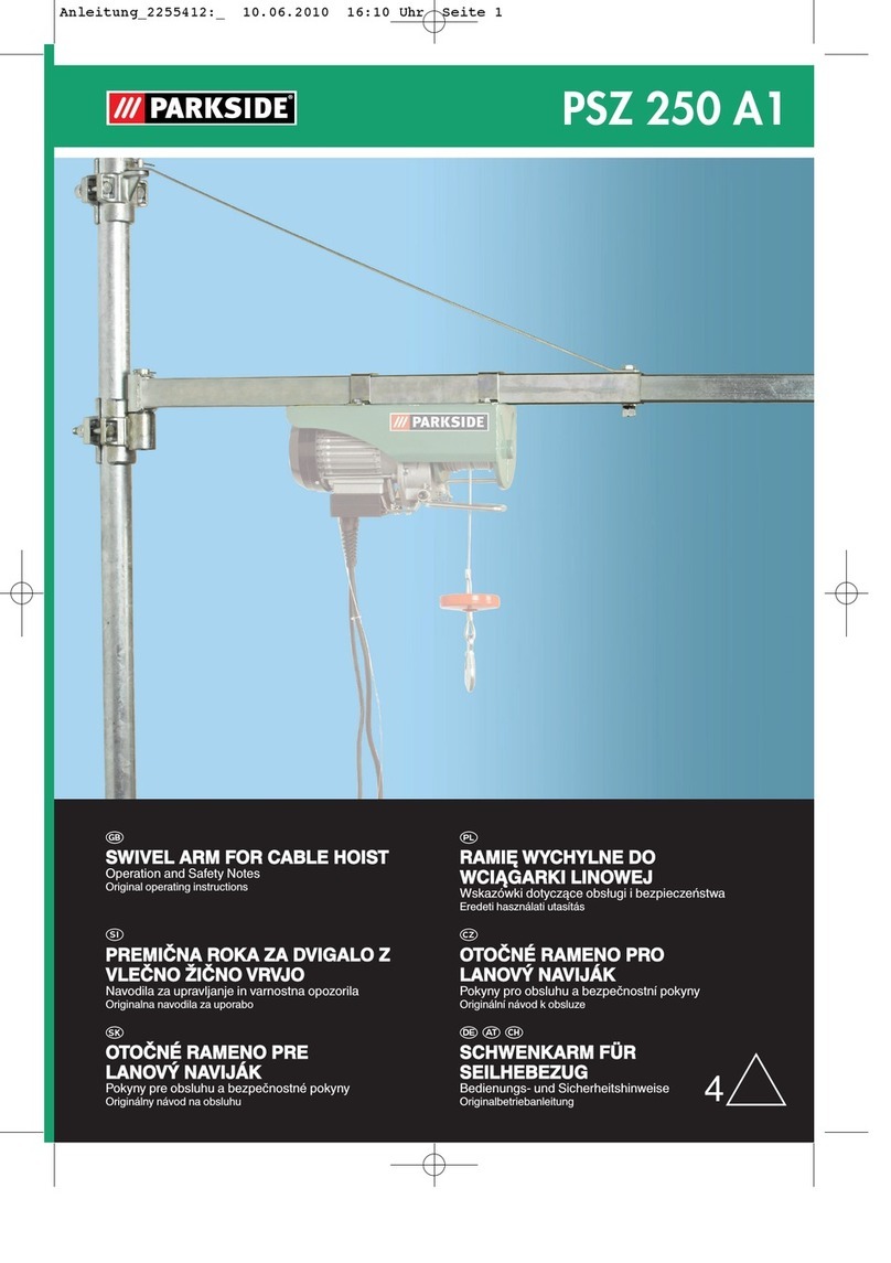
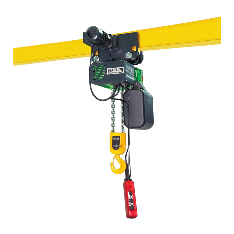
Urrea POEL01 Dimensions and installation guide

POEL01 POEL03
POEL07 POEL09POEL11 MANUAL DE USUARIO Y
GARANTÍA.
USER’S MANUAL AND WARRANTY.
POLIPASTO ELÉCTRICO
ELECTRIC CHAIN HOIST
ATENCIÓN: lea, entienda y siga las instrucciones de seguridad contenidas en este
manual antes de operar esta herramienta.
WARNING: read, understand and follow the safety rules in this manual, before operating this tool.

General safety rules
General Specifications
Technical data
Maintenance
Troubleshooting
Notes
Warranty policy
Normas generales de seguridad
Especificaciones generales
Especificaciones técnicas
Mantenimiento
Solucionador de problemas
Notas
Garantía
10
10
13
13
15
17
18
3
4
6
6
9
17
18
ENGLISHESPAÑOL
CONTENIDO CONTENT
SÍMBOLOS SYMBOLS
PELIGRO, ADVERTENCIA, PRECAUCIÓN:
Indica un riesgo personal o la posibilidad
de un daño.
Herramientas tipo II: doble aislamiento,
protege las herramientas eléctricas.
DANGER, CAUTION, WARNING: indicates risk of
personal injury and/or the possibility of damage.
Type II power tools: indicates double insulation.
Utilice protección ocular y equipo de
seguridad recomendado para operar
esta máquina.
Wear eye protection and safety equipment
recommended to operate this machine.
2

NORMAS GENERALES DE SEGURIDAD
Este PRODUCTO tiene características que harán
su trabajo más rápido y fácil. Seguridad, como-
didad y confiabilidad fueron previstos como
prioridad para el diseño del mismo, haciendo
más fácil su operación.
ADVERTENCIA: lea todas las advertencias de
seguridad y todas las instrucciones. La omisión
de alguna de las advertencias e instrucciones
que se en listan a continuación puede dar como
resultado un choque eléctrico, fuego y/o un da-
ños serios. CONSERVE TODAS LAS ADVERTEN-
CIAS Y TODAS LAS INSTRUCCIONES.
NOTA: la expresión “herramienta” en las adver-
tencias se refiere a la herramienta eléctrica que
se conecta a la fuente de alimentación (con ca-
ble) o a la herramienta que se acciona a batería
(sin cable).
Si el funcionamiento del polipasto eléctrico no
se realiza de forma segura, pueden producirse
situaciones de peligro potenciales que, en caso
de no evitarse, podrían causar graves daños per-
sonales e incluso la muerte.
Para evitar dichas situaciones, el operario debe
respetar las siguientes recomendaciones:
-NO ponga en funcionamiento el polipasto has-
ta que no haya leído con detenimiento y com-
prendido el presente Manual de
Operaciones y Mantenimiento .
-NO utilice el polipasto para elevar o transportar
personas.
-NO utilice el polipasto, sobrepasando la capaci-
dad nominal de carga especificada en el mismo.
-NO utilice el polipasto si la cadena de carga esta
desgastada, dañada, torcida o doblada.
-NO eleve carga por encima de personas.
-NO ponga en funcionamiento el polipasto has-
ta que la zona de transporte de carga este com-
pletamente despejada.
-NO ponga en funcionamiento el polipasto has-
ta que la carga no se encuentre centrada en el
mismo.
Proteja la cadena de carga del polipasto de sal-
picaduras de soldaduras u otros contaminantes
que puedan dañarla.
-NO utilice la cadena como si fuera una eslinga,
ni rodee con la misma la carga para transpor-
tarla.
-NO coloque ningún tipo de carga en la punta
del gancho ni en el dispositivo de fijación del
mismo.
-NO deje el polipasto cargado sin haber tomado
las precauciones de seguridad necesarias.
-NO utilice la cadena de carga o el gancho como
toma de tierra cuando vaya a realizar trabajos
de soldadura.
-NO retire ni oculte los símbolos y recomenda-
ciones de advertencia del polipasto.
-NO ponga en funcionamiento un polipasto sin
pegatinas ni placas de advertencia o bien, si las
mismas son ilegibles.
-NO ponga en funcionamiento el polipasto has-
ta que no este correctamente asegurado a un
soporte.
-NO ponga en funcionamiento el polipasto has-
ta que las eslingas de carga u otros dispositivos
de carga autorizados no estén correctamente
ajustados y asentados en la garganta del gan-
cho.
Eleve la carga con cuidado y asegúrese que la
misma esta nivelada y se mantiene adecuada-
mente antes de continuar con el proceso.
Desconecte el polipasto que presente un fun-
cionamiento defectuoso e informe de dicho
problema.
Asegúrese que los dispositivos del sistema de
parada de marcha del polipasto funcionen ade-
cuadamente, en los dos sentidos.
Advierta al personal cuando la carga se vaya
acercando al lugar en que se encuentren.
Asegúrese de que los dispositivos de fijación de
ganchos estén cerrados y no soportan de ningu-
na manera el peso de la carga.
Asegúrese de que la carga pueda moverse libre-
mente y retire cualquier obstáculo que pueda
interferir en la trayectoria de la misma.
Evite el balanceo de la carga, cuando se está
trasladando.
Inspeccione el polipasto con regularidad y lleve
a cabo los registros de mantenimiento adecua-
dos.
-NO se distraiga cuando esté en funcionamiento
el polipasto.
3
ESPAÑOL•Manual de usuario

ESPECIFICACIONES GENERALES
Aparejo eléctrico con traslación - linea empuje
CAPACIDAD VEL. IZAJE
mts/ min
RAMALES MOTOR PESO
1/2 t 5,6 1-6 mm 3/4 HP
1000 rpm
35,5
1 T 2,64 2-6mm 38
2 T 3 2-8 mm 1/2 HP
1400 rpm
75
3 T 3 2-8 mm 77
5 T 1,25 2-10 mm 2 HP
1400 rpm 135
Aparejo eléctrico con traslación - linea eléctrica
CAPACIDAD VEL. IZAJE
mts/ min
RAMALES MOTOR PESO
1/2 T 5,6 1-6 mm
0,30 HP
750 rpm
35,5
1 T 2,64 2-6mm 38
2 T 3 2-8 mm 75
3 T 3 2-8 mm 77
5 T 1,25 2-10 mm 0,5 HP
750 rpm 135
CONEXIÓN DE MICROS
Ubicar balancín de corte de micros (1) en el
soporte (3) en la dirección pre ensamblada en
la que fue embalada.
Luego sujetarlo por medio de umbracos 3/16W
(2).
POSICIONAMIENTO DE REGULADOR DE
CONTADOR
DOBLE REDUCCIÓN
1.Insertar subconjunto.
1
2
3
Eje ruedas
4

1.Insertar subconjunto A.
TRIPLE REDUCCIÓN
1.Insertar subconjunto A.
2.Insertar subconjunto.
SUBCOJUNTO
A
SUBCOJUNTO
B
SUBCOJUNTO
A
SUBCOJUNTO
B
DOBLE REDUCCIÓN
5
ESPAÑOL•Manual de usuario

3.Insertar subconjunto B.
ESPECIFICACIONES TÉCNICAS
POEL01
CAPACIDAD 0.5 T
POTENCIA 0.75 W
VOLTAJE 220-60 V
LONGITUD DE CADENA 3.5 m
PESO TOTAL 35.5 kg / 59 Kg
POEL03
CAPACIDAD 1 T
POTENCIA 0.75 W
VOLTAJE 220-60 V
LONGITUD DE CADENA 7 m
PESO TOTAL 38 kg / 63 Kg
POEL07
CAPACIDAD 2 T
POTENCIA 1.5 W
VOLTAJE 220-60 V
LONGITUD DE CADENA 13 m
PESO TOTAL 75 kg / 89 Kg
POEL09
CAPACIDAD 3 T
POTENCIA 1.5 W
VOLTAJE 220-60 V
LONGITUD DE CADENA 13 m
PESO TOTAL 77 kg / 91 Kg
POEL11
CAPACIDAD 5 T
POTENCIA 2.5 W
VOLTAJE 220-60 V
LONGITUD DE CADENA 13 m
PESO TOTAL 135 kg / 145 Kg
MANTENIMIENTO
Las inspecciones y el mantenimiento que se le
realice al polipasto, debe estar a cargo de gente
idónea, debiéndose establecer las frecuencias
adecuadas al trabajo al cuál está sometido el
equipo.
VERIFICACIÓN DE ESTADO DEL GANCHO
Realice una inspección en el gancho semanal-
mente.
Reemplace, en cualquiera de los siguientes ca-
sos:
1-Deformación de la garganta, superior a un
15%.
2-Que se encuentre doblado o torcido más de
10° de su plano normal.
Una vez al año, realice ensayos, en lo que se
refiere a estructura del material, para detectar
fallas que a simple vista no se pueden apreciar.
La prueba que puede realizarse es penetración
por tinte.
En caso de encontrarse alguna alteración en la
estructura del material, reemplace el gancho.
3-Inspecciones el pestillo de seguridad colocado
en el gancho y compruebe si realiza la función
de cerrar la abertura de la garganta del gancho
de manera segura cuando se coloca la carga.
Los dispositivos utilizados para el movimiento
de cargas, no deben afectar la forma del pestillo
y permitir que éste cierre cuándo se comienza a
trabajar con el polipasto. De esa manera estará
cumpliendo la función de mantener el dispo-
sitivo colocado, sin peligro de que se salga del
gancho.
6

4-El bulón de sujeción de la cadena, debe ser de
acero de grado 8, correspondiente a todas las
capacidades, difiriendo de acuerdo a cada capa-
cidad la medida del bulón.
Con respecto a los modelos que tengan doble
tiro de cadena, deben asegurarse de que en la
reducción estén presentes los tres bulones de
sujeción, que cuenten con arandelas de seguri-
dad, y de que el bulón no se encuentre doblado
o que haya sido reemplazado por otro que no
corresponda con las características de seguridad
establecidas.
5-Controlar la lubricación y el ajuste de la crapo-
dina. Verificar posibles desgastes.
Desarmar y engrasar cuando corresponda.
Mantener siempre el movimiento del gancho.
6-Para la capacidad de 1, realizar la revisión de
los rodamientos de soporte de la polea.
Verificar el ajuste de los bulones de las placas
laterales.
Verifique que la cadena no se encuentre cruza-
da cuando ingresa a la reducción.
Verifique que la polea de la reducción no esté
rota o presente desgaste y que sea la adecuada
de acuerdo a la medida de cadena.
VERIFICACIÓN DE ESTADO DE LA CADENA
La cadena debe mantenerse limpia y lubricada.
Revise visualmente la cadena cada vez que usa
el polipasto.
El polipasto no debe operarse cuando la cadena
esté retorcida o enredada.
Una fase importante del mantenimiento del po-
lipasto es la inspección de la cadena. Revise cada
eslabón individualmente para determinar si hay
alargamiento de la cadena.
IMPORTANTE: Las dimensiones de la cadena
utilizada en el polipasto son normalizadas y la
polea de centro fue adaptada a dichas medidas.
No trate de cambiarla por cadena de otro fabri-
cante.
1-Revise la cadena para ver si hay desgaste gene-
ral o alargamiento. Para esto, realice lo siguien-
te: elija un tramo sin desgaste ni alargamiento
(por ejemplo en el extremo suelto), deje que la
cadena cuelgue verticalmente con una carga li-
gera (unos 10 kg) para que quede tirante. Mida
la longitud exterior de un número conveniente
de eslabones (unos 30 cm). Haga lo mismo con
un número de eslabones de una sección usada
de cadena y calcule el porcentaje de aumento
en la longitud de la cadena usada.
2-Si la longitud de la cadena que se encuentra
en uso, supera el 1 1/2 % en comparación con el
tramo de cadena que está sometida a menos uso
(tomando como referencia la cadena que se en-
cuentra en el extremo opuesto al gancho) lo que
representa 4,5 mm de 30 cm entonces la cadena
debe reemplazarse.
Si la cadena se ha gastado, pero su valor no su-
pera el 1 1/2 %, revísela en otros tramos a lo
largo de su extensión y realice un control más
detallado teniendo en cuenta de que el proble-
ma se pudiera agravar.
IMPORTANTE: En el momento de necesitar un
tramo de cadena más largo, se debe realizar el
cambio completo de la cadena (sumándole los
metros adicionales), dado que el fabricante, no
admite soldaduras ni empalmes.
VERIFICACIÓN DE CIRCUITO ELÉCTRICO
Todos los polipastos eléctricos se entregan listos
para comenzar a operar.
El usuario solo tiene que realizar la conexión a la
línea de alimentación, de acuerdo a las especifi-
caciones establecidas por el fabricante y colocar
las protecciones adecuadas como Disyuntor di-
ferencial, Interruptor termo magnético y guarda
motor, los cuáles quedan a criterio y responsabi-
lidad del usuario.
La instalación, revisión o reparación del circui-
to eléctrico o de algún componente del mismo,
debe estar a cargo de personal calificado.
Respetar las características de los elementos co-
locados en el sistema eléctrico del polipasto, en
el caso que debiera reemplazar alguno.
No se debe realizar ninguna tarea de manteni-
miento o inspección, sin antes haber interrum-
pido el suministro
de energía del tablero de acometida de alimen-
tación del polipasto.
7
ESPAÑOL•Manual de usuario

REGULACIÓN DE MOTORES ELÉCTRICOS
TRIFÁSICOS CON FRENO INCORPORADO
Aparejos de ½ y 1 Tn.
Este modelo de motor cuenta con un mecanis-
mo interno de frenado mecánico por resorte,
que permite que la carga del aparejo sea deteni-
da en cualquier punto de su carrera de elevación
o de descenso. El sistema de frenado es liberado
automáticamente por medios electromagnéti-
cos cada vez que se energiza el motor, permi-
tiendo así su giro.
1 - Tuerca ranurada de ajuste
2 - Tuerca de registro (porta-rodamiento)
3 - Ventilador plástico
4 - Capuchón de chapa
5 - Resorte del mecanismo de freno
6 - Tuerca (hexágono de 10 mm.)
REGULACIÓN DE LA TENSIÓN DEL RESORTE DE
FRENADO
La tensión del resorte del sistema de frenado
debe regularse en el punto justo para que el
funcionamiento del motor sea el óptimo: por un
lado, si el resorte queda muy flojo, el freno no
podrá sostener a la carga del aparejo; por otro
lado, si el resorte se ajusta demasiado, las co-
rrientes internas del motor no podrán despegar
el freno. Esto último sería muy grave, ya que el
motor giraría frenado tanto en elevación como
en descenso, y podría quemarse fácilmente.
El motor funciona correctamente cuando al
energizarlo y desenergizarlo se escucha un gol-
pe seco ocasionado por el freno cuando se libera
y cuando se bloquea. En caso de que debiera re-
gularse la tensión del resorte porque el freno no
trabaja, deberá procederse como sigue:
Retirar el capuchón de chapa que cubre el venti-
lador plástico del motor.
Regular por medio de una llave tipo tubo la
tuerca (hexágono de 10 mm.), la cual es de rosca
derecha, de manera que debe tenerse en cuenta
lo siguiente:
-Hay problemas para frenar la carga.
Ajustar la tuerca.
-El motor gira frenado.
Aflojar la tuerca.
Se recomienda no girar esta tuerca más de una
vuelta por cada regulación que se realice.
Luego de cada regulación, comprobar el funcio-
namiento del freno encendiendo y apagando el
motor.
Si fuera necesario, repetir este procedimiento
hasta que el freno funcione correctamente.
Una vez regulado el freno, colocar nuevamente
el capuchón de chapa en su posición.
PROTECCIÓN MOTOR
Los polipastos eléctricos no cuentan con protec-
ciones térmicas o termomagnéticas de orden ge-
neral ni individual de cada motor, y se encuen-
tran todos los elementos de maniobra dentro
del mismo equipo conectados y listos para su
operación.
El calibre es de acuerdo al consumo del motor y
de la manera que se quiera proteger los moto-
res. Lo correcto sería colocar protecciones indi-
viduales a cada motor, térmica o guardamotor.
Los consumos aproximados son:
Motor polipasto: 5 A
Motor carro de tranlación: 1,5 A
8

SOLUCIONADOR DE PROBLEMAS
En el izaje y/o descenso, la carga no se detiene
a la altura deseada.
Causa:
1- Micro defectuoso.
2- Error en el conexionado.
Solución:
1- Verifique y reemplace por otro de iguales ca-
racterísticas.
La botonera de comando no responde.
Causa:
1- Verifique la tensión de línea.
2- Verifique la tensión del secundario del trans-
formador.
3- Pulsador/es defectuoso/s.
4- Cable de la botonera de comando cortado.
5- Cables flojos en la botonera de comando o en
las borneras de la caja de comando.
6- Disparo de protecciones termomagnéticas.
Solución:
1- Asegúrese que la tensión de línea esté de
acuerdo a la placa nominal del motor.
2- Verifique que tenga 24 V CA, de lo contrario,
reemplace por otro de iguales características.
3- Verifique y reemplace por otro/s de iguales
características.
4- Verifique y reemplace el tramo completo por
otro de iguales características.
5- Realice un ajuste general de los bornes.
6- Verifique las protecciones en el tablero de
acometida de alimentación del polipasto.
La carga se puede izar pero no descender.
La carga se puede descender pero no izar.
Causa:
1- Pulsador defectuoso.
2- Micro accionado.
3- Contactor de la caja de comando defectuoso.
4- Terminales flojos en la botonera de comando,
bornera de paso o terminales del contactor.
5- Cable botonera de comando cortado.
Solución:
1- Reemplace por otro de iguales características.
2- Verifique que funcione correctamente, de ser
necesario, reemplace por otro de iguales carac-
terísticas.
3- Verifique y reemplace por otro de iguales Ca-
racterísticas.
4- Realice un ajuste general de todos los puntos
de conexiones eléctricas.
5- Verifique y reemplace el tramo completo por
otro de iguales características.
Cadena fuera de medida.
Causa:
1- Desgaste.
2- Cadena de distinta medida
Solución:
1- Ver “verificación estado de la cadena”
2- Utilice repuestos originales. Cambie todo el
tramo de cadena y verifique que la polea de
centro no haya perdido el paso.
Abertura del gancho.
Causa:
1- Exceso de carga
2- Incorrecta colocación del soporte o eslinga en
el gancho.
Solución:
1- Ver “verificación estado del gancho” 2- Colo-
car el soporte o eslinga para el movimiento de
cargas en la garganta del gancho, para que de
esa manera el pestillo pueda funcionar como
medida de seguridad. NUNCA colocar la carga
suspendida de la punta del gancho.
Motor con mucha temperatura.
Causa:
1- Excesivo ajuste en el registro del freno.
2- Exceso de carga de trabajo.
Solución:
1- Verifique el peso de las cargas a la que está
sometiendo al polipasto.
9
ENGLISH•User's Manual

GENERAL SAFETY RULES
This PRODUCT has features that will make your
job faster and easier. Safety, comfort and reli-
ability were provided as a priority for its design,
making its operation easier.
WARNING: read all safety warnings and all
instructions. Failure to follow any of the warn-
ings and instructions listed below could result in
electric shock, fire, and / or serious injury. SAVE
ALL WARNINGS AND ALL INSTRUCTIONS.
NOTE: The term “tool” in the warnings refers
to the power tool that connects to the power
source (corded) or the battery-operated tool
(cordless).
Failure to operate the electric hoist safely can
lead to dangerous situations.
Potential hazards which, if not avoided, could
cause serious personal injury or even death.
To avoid such situations, the operator must re-
spect the following recommendations:
-DO NOT put the hoist into operation until you
have carefully read and understood this Owner’s
Manual
Operations and maintenance .
-DO NOT use the hoist to lift or transport peo-
ple.
-DO NOT use the hoist, exceeding the rated load
capacity specified on it.
-DO NOT use the hoist if the load chain is worn,
damaged, twisted or bent.
-DO NOT lift loads over people.
-DO NOT operate the hoist until the cargo trans-
port area is completely clear.
-DO NOT operate hoist until load is centered on
hoist.
Protect the hoist load chain from weld spatter
or other contaminants that could damage it.
-DO NOT use the chain as a sling, or surround
the load with it to transport it.
-DO NOT place any type of load on the tip of the
hook or on its fixing device.
-DO NOT leave the hoist loaded without taking
the necessary safety precautions.
-DO NOT use the load chain or hook for ground-
ing when doing welding work.
-DO NOT remove or conceal the warning sym-
bols and recommendations from the hoist.
-DO NOT operate a hoist without warning labels
or stickers, or if they are illegible.
-DO NOT operate the hoist until it is properly
secured to a support.
-DO NOT operate the hoist until the load slings
or other authorized load devices are not proper-
ly adjusted and seated in the throat of the hook.
Raise the load carefully and make sure it is level
and properly held before continuing with the
process.
Disconnect the hoist that is malfunctioning and
report the problem.
Make sure that the hoist stop system devices
work properly, in both directions.
Warn personnel when cargo is approaching
their location.
Make sure that the hook fasteners are closed
and do not support the weight of the load in
any way.
Make sure the load can move freely and remove
any obstacles that may interfere with the path
of the load it self.
Avoid swaying the load when moving.
Inspect the hoist regularly and keep proper
maintenance records.
-DO NOT be distracted when the hoist is oper-
ating.
GENERAL SPECIFICATIONS
Electric hoist with translation - thrust line
CAPACITY
VEL.
LIFTING
mts/ min
BRANCHES MOTOR WEIGHT
1/2 T 5,6 1-6 mm 3/4 HP
1000 rpm
35,5
1 T 2,64 2-6mm 38
2 T 3 2-8 mm 1/2 HP
1400 rpm
75
3 T 3 2-8 mm 77
5 TON. 1,25 2-10 mm 2 HP
1400 rpm 135
10

Electric hoist with translation - electric line
CAPACITY
VEL.
LIFTING
mts/ min
BRANCHES MOTOR WEIGHT
1/2 T 5,6 1-6 mm
0,30 HP
750 rpm
35,5
1 T 2,64 2-6mm 38
2 T 3 2-8 mm 75
3 T. 3 2-8 mm 77
5 T 1,25 2-10 mm 0,5 HP
750 rpm 135
MIC CONNECTION
Locate the mic cutter rocker (1) on the brack-
et (3) in the pre-assembled direction in the one
that was packed.
Then fasten it by means of 3 / 16W umbracos (2).
COUNTER REGULATOR POSITIONING
DOUBLE REDUCTION
1.Insert subset.
1.Insert subset A.
1
2
3
Wheel axle
SUBCOJUNTO
A
SUBCOJUNTO
B
Subset A
Subset B
DOBLE REDUCCIÓN
DOUBLE REDUCTION
11
ENGLISH•User's Manual

TRIPLE REDUCTION
1.Insert subset A.
2.Insert subset.
3.Insert subset B.
SUBCOJUNTO
A
SUBCOJUNTO
B
Subset A
Subset B
TRIPLE REDUCTION
12

TECHNICAL DATA
POEL01
CAPACITY 0.5 T
POWER 0.75 W
VOLTAGE 220-60 V
CHAIN LENGTH 3.5 m
TOTAL WEIGHT 35.5 kg / 59 Kg
POEL03
CAPACITY 1 T
POWER 0.75 W
VOLTAGE 220-60 V
CHAIN LENGTH 7 m
TOTAL WEIGHT 38 kg / 63 Kg
POEL07
CAPACITY 2 T
POWER 1.5 W
VOLTAGE 220-60 V
CHAIN LENGTH 13 m
TOTAL WEIGHT 75 kg / 89 Kg
POEL09
CAPACITY 3 T
POWER 1.5 W
VOLTAGE 220-60 V
CHAIN LENGTH 13 m
TOTAL WEIGHT 77 kg / 91 Kg
POEL11
CAPACITY 5 T
POWER 2.5 W
VOLTAGE 220-60 V
CHAIN LENGTH 13 m
TOTAL WEIGHT 135 kg / 145 Kg
MAINTENANCE
Inspections and maintenance carried out on the
hoist must be carried out by suitable people,
and must establish the appropriate frequencies
for the work to which the equipment is subject-
ed.
HOOK STATUS VERIFICATION
Perform an inspection on the hook weekly.
Replace, in any of the following cases:
1-Deformation of the throat, greater than 15%.
2-That it is bent or twisted more than 10 ° from
its normal plane.
Once a year, test the structure of the material
to detect flaws that cannot be seen with the na-
ked eye. The test that can be performed is dye
penetration.
If any alteration is found in the material struc-
ture, replace the hook.
3-Inspect the safety latch placed in the hook
and check if it performs the function of closing
the throat opening of the hook safely when the
load is placed.
The devices used for the movement of loads
must not affect the shape of the latch and allow
it to close when working with the hoist. That
way it will be fulfilling the function of keeping
the device in place, without danger of it coming
off the hook.
4-The chain fastening bolt must be made of
grade 8 steel, corresponding to all the capaci-
ties, differing according to each capacity the
size of the bolt.
With regard to models with double chain pull,
you must ensure that in the reduction, the three
fastening bolts are present, that they have safe-
ty washers, and that the bolt is not bent or that
it has been replaced by another that does not
correspond to the established safety character-
istics.
5-Check the lubrication and the adjustment of
the crapodin. Check for possible wear.
Disassemble and grease where appropriate.
Always keep the hook moving.
6-For the capacity of 1, check the pulley support
bearings.
Check the tightness of the side plate bolts.
Check that the chain is not crossed when enter-
ing the reduction.
Check that the reduction pulley is not broken or
present wear and that it is adequate according
to the chain size.
CHAIN STATUS VERIFICATION
The chain must be kept clean and lubricated.
Visually check the chain each time you use the
hoist.
The hoist must not be operated when the chain
is twisted or tangled.
An important phase of hoist maintenance is the
inspection of the chain. Check every link indi-
vidually to determine if there is elongation of
the chain.
IMPORTANT: The dimensions of the chain used
in the hoist are standardized and the center pul-
ley was adapted to these measures. Do not try
to exchange it for a chain from another man-
ufacturer.
13
ENGLISH•User's Manual

1-Check the chain to see if there is general wear
or elongation. To do this, do the following:
choose a length without wear or elongation (for
example at the loose end), let the chain hang
vertically with a light load (about 10 kg) so that
it is taut. Measure the outer length of a suitable
number of links (about 30 cm). Do the same for
a number of links in a used section of chain and
calculate the percentage increase in the length
of the used chain.
2-If the length of the chain that is in use, ex-
ceeds 1 1/2% compared to the section of chain
that is subjected to less use (taking as a refer-
ence the chain that is at the end opposite the
hook) representing 4.5mm of 30cm then the
chain needs to be replaced.
If the chain has worn out, but its value does not
exceed 1 1/2%, check it in other sections along
its length and carry out a more detailed con-
trol, taking into account that the problem could
worsen.
IMPORTANT: When you need a longer length of
chain, you must make the complete change of
the chain (adding the additional meters), since
the manufacturer does not allow welding or
splices.
ELECTRICAL CIRCUIT VERIFICATION
All electric hoists are delivered ready to start
operating.
The user only has to make the connection to the
power line, according to the specifications es-
tablished by the manufacturer and place the ap-
propriate protections such as differential circuit
breaker, thermo-magnetic switch and motor
guard, which are at the discretion and respon-
sibility of the user.
The installation, revision or repair of the electri-
cal circuit or of any component thereof, must be
carried out by qualified personnel.
Respect the characteristics of the elements
placed in the hoist’s electrical system, in the
event that should replace some.
No maintenance or inspection must be carried
out without first interrupting the supply power
supply connection panel of the hoist.
REGULATION OF THREE PHASE ELECTRIC
MOTORS WITH BUILT-IN BRAKE
Rigs of ½ and 1 Tn.
This motor model has an internal mechanical
spring braking mechanism, which allows the
load of the rig to be stopped at any point in its
lifting or lowering stroke. The braking system
is automatically released by electromagnetic
means each time the motor is energized, thus
allowing it to rotate.
1 - Slotted Adjusting Nut
2 - Registration nut (bearing holder)
3 - Plastic fan
4 - Sheet metal cap
5 - Brake mechanism spring
6 - Nut (10 mm hexagon)
14

ADJUSTING THE TENSION OF THE BRAKING
SPRING
The tension of the spring of the braking system
must be regulated at the right point so that the
operation of the motor is optimal: on the one
hand, if the spring is too loose, the brake will
not be able to hold the load of the rigging; for
another
On the other hand, if the spring is adjusted
too much, the internal currents of the motor
will not be able to release the brake. The latter
would be very serious, since the engine would
rotate under braking both in elevation and de-
scent, and could easily burn out.
The motor operates correctly when energized
and de-energized, a sharp thump is heard from
the brake when released and when it locks. If
the spring tension should be adjusted because
the brake does not work, proceed as follows:
Remove the sheet metal cap that covers the
plastic fan from the motor.
Adjust the nut (10 mm hexagon), which has a
right-hand thread, using a pipe wrench, so that
the following must be taken into account:
-There are problems stopping the load.
Tighten the nut.
-The motor rotates under braking.
Loosen the nut.
It is recommended not to turn this nut more
than one turn for each adjustment made.
After each adjustment, check the operation of
the brake by turning the motor on and off.
If necessary, repeat this procedure until the
brake works properly.
Once the brake is adjusted, put the sheet metal
cap back in position.
MOTOR PROTECTION
Electric hoists do not have general or individ-
ual thermal or thermomagnetic protections of
each motor, and all the maneuvering elements
are within the same equipment connected and
ready for your operation.
The caliber is according to the consumption of
the motor and in the way that the motors are
to be protected. The correct thing would be to
place individual protections to each motor, ther-
mal or motor guard.
The approximate consumptions are:
Hoist motor: 5 A
Drive car motor: 1.5 A
TROUBLESHOOTING
On lifting and / or lowering, the load does not
stop at the desired height.
Cause:
1- Defective microphone.
2- Error in the connection.
Solution:
1- Check and replace with another of the same
features.
The command keypad does not respond.
Cause:
1- Check the line voltage.
2- Check the secondary voltage of the trans-
former.
3- Button / is defective / s.
4- Cable of the command button cut.
5- Loose cables in the control keypad or in the
control box terminals.
6- Triggering of thermomagnetic protections.
Solution:
1- Make sure that the line voltage is according
to the motor rating plate.
2- Verify that it has 24VAC, otherwise, replace
with another with the same characteristics.
3- Check and replace with other (s) of the same
features.
4- Check and replace the entire section by an-
other with the same characteristics.
5- Make a general adjustment of the terminals.
6- Check the protections on the dashboard hoist
supply connection.
The load can be raised but not lowered.
The load can be lowered but not lifted.
Cause:
1- Defective button.
2- Micro powered.
3- Contactor of the control box defective.
4- Loose terminals on the command keypad, ter-
minal block or contactor terminals.
5- Control button cable cut.
Solution:
1- Replace with another with the same charac-
teristics.
2- Verify that it works correctly, if necessary, re-
place with another of the same features.
3- Check and replace with another of the same
characteristics.
4- Make a general adjustment of all electrical
connection points.
5- Check and replace the entire section by an-
other with the same characteristics.
15
ENGLISH•User's Manual

Chain out of measure.
Cause:
1- Wear.
2- Chain of different sizes
Solution:
1- See “chain status verification”
2- Use original spare parts. Change all chain sec-
tion and check that the chain pulley center has
not missed the step.
Hook opening.
Cause:
1- Excess load
2- Incorrect positioning of the support or sling
on the hook.
Solution:
1- See “hook status verification” 2- Place the
support or sling for movement of loads in the
throat of the hook, so that the latch can func-
tion as a security measures. NEVER place the
load suspended from the tip of the hook.
Very hot engine.
Cause:
1- Excessive adjustment in the brake register.
2- Excess workload.
Solution:
1- Check the weight of the loads you are sub-
jecting the hoist.
16

Notas / Notes
17
Manual de usuario • User’s manual

POEL01·POEL03
POEL07·
POEL09·POEL11
URREA HERRAMIENTAS PROFESIONALES S.A.
DE C.V. Warranties this product for a period of 1
year in its parts, components and manual labour
against any manufacture defect from the purchas-
ing date.
Purchase date: ____/____/____
Product:____________________
Brand:______________________
Model:______________________
______________________________
Distributor seal and signature
Sold and Imported by:
URREA HERRAMIENTAS PROFESIONALES S.A. DE
C.V. Carretera a El Castillo, km 11.5, C.P. 45680,
El Salto, Jalisco, México. R.F.C. UHP900402Q29.
Terms:
In order to make warranty effective you must pres-
ent the product along with the warranty properly
filled and signed to an authorized distributor or
service center.
Present the invoice or ticket with official registra-
tion info of the trade from where the product was
purchased. The guarantee is effective as of the date
of purchase stated on the invoice or ticket; or with
the distributor’s stamp (with delivery date in this
policy).
URREA HERRAMIENTAS PROFESIONALES S.A.
DE C.V. Will cover the transportation cost related
to the warranty.
This warranty is not applicable in the follow-
ing cases:
· When the product has not been used according to
normal conditions or natural wear of its parts.
· When the product has not been used according
with this user’s manual instructions.
· When the product has been fixed or modified by
unauthorized or unqualified person.
URREA HERRAMIENTAS PROFESIONALES S.A.
DE C.V. garantiza este producto por el termino de
1 año en sus piezas, componentes y mano de obra
contra cualquier defecto de fabricación a partir de
la fecha de entrega.
Fecha de venta: ____/____/____
Producto: ___________________
Marca: ______________________
Modelo: ____________________
______________________________
Sello y firma de distribuidor
Comercializado e Importado por:
URREA HERRAMIENTAS PROFESIONALES S.A. DE
C.V. Carretera a El Castillo, km 11.5, C.P. 45680,
El Salto, Jalisco, México. R.F.C. UHP900402Q29.
Condiciones:
Para hacer efectiva la garantía deberá presentar
el producto junto con la póliza de garantía debi-
damente firmada y sellada por el establecimiento
donde la adquirió, en cualquiera de los centros de
servicio autorizados.
Presentar la factura o ticket con datos fiscales del
comercio de donde se adquirió el producto. La ga-
rantía cuenta a partir de la fecha de la nota o factu-
ra de compra o el sello con fechador del distribuidor
(con fecha de entrega en esta póliza).
Los gastos de transportación que se deriven del
cumplimiento de la garantía serán cubiertos por:
URREA HERRAMIENTAS PROFESIONALES S.A.
DE C.V.
Esta garantía no será valida en los siguientes
casos:
· Cuando el producto haya sido utilizado en condi-
ciones distintas a las normales o al desgaste natural
de sus partes.
· Cuando el producto no haya sido operado de
acuerdo al instructivo de uso que lo acompaña.
· Cuando el producto haya sido alterado o reparado
por personas no autorizadas.
ESPAÑOL
PÓLIZA DE GARANTÍA
ENGLISH
WARRANT POLICY
18
This manual suits for next models
4
Table of contents
Languages:
Other Urrea Chain Hoist manuals
Popular Chain Hoist manuals by other brands

Tractel
Tractel tralift TE Series Operation and maintenance manual

Vital
Vital V-Lever VR2 user manual

CM
CM Bandit BAN07505 Operating, Maintenance & Parts Manual

R&M
R&M LOADMATE LM 16 Installation & maintenance instructions

Lange Originals
Lange Originals Hoist-A-Top Simple installation instructions

Toolland
Toolland MP78 user manual