USA Industries GRIPSAFE Series User manual

Patents & Trademarks
- US PATENTS: 9,927,058 | 9,810,364 | D894,349 | 10,746,339
- CANADIAN PATENT: 3,004,787
- CANADIAN INDUSTRIAL DESIGN: CA 186293
- EUROPEAN PATENT: 3,377,797 B1
- EUROPEAN PATENT [Germany]: 602016051864.3
- EUROPEAN UNION DESIGN REGISTRATION: 00628264-001
- INTERNATIONAL TRADEMARK REGISTRATION: 1550298
- Other US and Foreign Patents Pending
®
INSTALLATION MANUAL
www.USAIndustries.com
(713) 941-3797 • (800) 456-8721
315 State Street • S. Houston, TX 77587
Small Double Block and Bleed (DBB) Plug
Manufactured Exclusively by USA Industries, Inc.
an ISO 9001:2015 Certifi ed Company

www.USAIndustries.com | (713) 941-3797
©2021, USA Industries, Inc.
FRM-22.1 Rev.G
For most current patent and trademark identifi cations, go to:
https://www.USAIndustries.com/piping-isolation-products/Gripsafe-Patents-Trademarks/
Contents
1. Introduction 2
2. Safety 3
3. Parts 4
4. Specications 6
5. Preparing the GripSafe DBB Plug for Installation 8
6. Installing the GripSafe DBB Plug 9
7. Positioning for Between the Seal Hydro Testing 12
8. Instructions for Cooling Flow Between the Seals 13
9. GripSafe DBB Plug Removal 14
1. Introduction
USA Industries, Inc. thanks you for choosing GripSafe pipe plugging technology. is manual covers the
proper use of this technology to ensure safe operating conditions.
WA R NI NG :
Do not use GripSafe equipment before fully reading and comprehending this manual. Failure to follow
this manual in full may result in injury and/or damage to equipment.
All necessary sockets, wrenches and liing device to install this equipment are available for rental or purchase
from USA Industries, Inc. See Section 4, Table 2 for sockets and check valves and Table 4 for liing device.
e information in this manual is for the use of a GripSafe plug in metallic piping. If the intended use of
this plug is for any piping other than metallic piping, please contact USA Industries, Inc.’s Customer Service
Department for technical support.
Page 2of 16

www.USAIndustries.com | (713) 941-3797
©2021, USA Industries, Inc.
FRM-22.1 Rev.G
For most current patent and trademark identifi cations, go to:
https://www.USAIndustries.com/piping-isolation-products/Gripsafe-Patents-Trademarks/
2. Safety
Failure to follow proper safety requirements may result in the GripSafe plug failing, which could lead to injury,
material loss, and/or damage to equipment.
Wear proper Personal Protective Equipment (PPE) when performing any task with the GripSafe plug as dened by
site safety rules. Always follow site procedure for safely liing and operating equipment.
Never install the GripSafe plug in a position where the Gripping Wedge would be located over weld droop or ridge.
Never install the Seals or Gripping Wedge over a section of pipe that is missing its interior wall; i.e. weldolet, tee,
etc.
Pressure testing can be a hazardous operation and safety precautions are important. Never stand or pass in front
of a test plug during installation, testing, and removal.
Do not make adjustments to the plug, safety equipment, or vessel while the plug is under pressure.
Do not exceed rated pressure stamped on the plug. Plugs are rated for holding pressure in one direction; never
apply pressure on the non-rated side of the plug.
Backpressure rating on the references the plugs ultimate holding capacity. Never exceed the pressure capacity of
the weakest component in a pressurized system. Study your system’s components prior to beginning a pressure
test to ascertain and conrm that the maximum test pressure of your system is subjected to is in accordance with
all applicable industry and site-specic standards.
We recommend using Water as the test medium. Before pressurizing the system, vent all gases from the vessel.
If pneumatic testing, all attempts to limit potential damage to personnel or equipment is critical. USA Industries,
Inc. recommends Nitrogen as the medium for pneumatic testing as it does not support combustion. Follow
provisions outlined in ASME PCC-2 Repair of Pressure Equipment and Piping when testing pneumatically.
Carefully observe the location of the pipe where the Wedge Grippers make contact when performing a hydro test.
If you observe any deformation or swelling of the pipe, stop immediately and slowly release the pressure from the
system. Contact USA Industries, Inc. for further assistance.
If you hear a popping or clicking sound at any time during a hydro test, STOP IMMEDIATELY and slowly release
the pressure from the system. Popping or clicking sounds during hydro testing may be a sign of the Wedge Gripper
slipping, cracking, or one of the plug components failing. Remove the plug from the pipe or tting and inspect for
damage. Contact USA Industries, Inc. for further assistance.
Make sure the plug is clean of debris and contaminants. Each Wedge Gripper should freely slide up and down in
its slot with a full range-of-motion, and incur no resistance. If you experience impeded movement due to debris,
dirt or contaminants, the plug may not grip the pipe’s ID securely, which can cause plug ejection under pressure,
potentially leading to injury, death, material loss, and/or damage.
For any questions or concerns, contact USA Industries, Inc. for technical assistance.
Page 3of 16

www.USAIndustries.com | (713) 941-3797
©2021, USA Industries, Inc.
FRM-22.1 Rev.G
For most current patent and trademark identifi cations, go to:
https://www.USAIndustries.com/piping-isolation-products/Gripsafe-Patents-Trademarks/
3. Parts (is manual references the part numbers identied below throughout the document)
Figure 1: GripSafe Mid-Grip DBB Diagram
Figure 2: With Optional Valve and Port for Cooling (Upon Request)
Page 4of 16

www.USAIndustries.com | (713) 941-3797
©2021, USA Industries, Inc.
FRM-22.1 Rev.G
For most current patent and trademark identifi cations, go to:
https://www.USAIndustries.com/piping-isolation-products/Gripsafe-Patents-Trademarks/
Table 1: GripSafe Bill of Materials
Page 5of 16

www.USAIndustries.com | (713) 941-3797
©2021, USA Industries, Inc.
FRM-22.1 Rev.G
For most current patent and trademark identifi cations, go to:
https://www.USAIndustries.com/piping-isolation-products/Gripsafe-Patents-Trademarks/
4. Specications
Figure 2: GripSafe DBB Dimensions Diagram
Page 6of 16

www.USAIndustries.com | (713) 941-3797
©2021, USA Industries, Inc.
FRM-22.1 Rev.G
For most current patent and trademark identifi cations, go to:
https://www.USAIndustries.com/piping-isolation-products/Gripsafe-Patents-Trademarks/
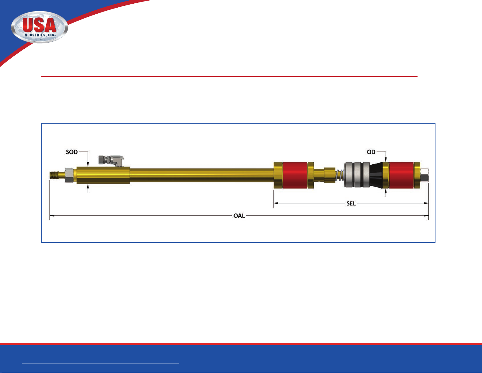
Table 2: GripSafe DBB Specications
Page 7of 16
Nominal
Pipe Size
(in)
Schedule Part Number
Tool
Diameter
(in)
Rec.
ID Range
(in)
Nominal
Pipe ID
Clearance
(in)
Approx.
Tool
Weight
(lbs)
Tool
Length
(in)
Torque Range
(ft-lbs)
Comp.
Hex Nut
Socket
Size
(in)
Backup
Wrench Size
(in)
Fill Port
Thread
Back
Pressure
Vent
Thread
Back
Pressure
Rating
(PSI)
Between
the
Seal Test
Pressure
(PSI)
Norm Max.
3/4
40,STD,40S GS-D-S-0075-040 0.79 0.81 - 0.91 0.035 2.5 25.38 3.0 5.0 9/16 1/4 Open End 1/4” FNPSM 1/16 MNPT 10000 2500
80,XS,80S GS-D-S-0075-080 0.71 0.73 - 0.80 0.035 2.4 25.38 2.0 3.5 9/16 1/4 Open End 1/4” FNPSM 1/16 MNPT 10000 2500
1
10 GS-D-S-0100-010 0.99 1.01 - 1.15 0.103 2.8 25.38 5.5 8.5 9/16 1/4 Open End 1/4” FNPSM 1/16 MNPT 2825 2500
40,STD,40S GS-D-S-0100-040 0.99 1.02 - 1.15 0.055 2.7 25.38 5.5 8.5 9/16 1/4 Open End 1/4” FNPSM 1/16 MNPT 10000 2500
80,XS,80S GS-D-S-0100-080 0.90 0.93 - 1.04 0.055 2.6 25.38 1.5 7.0 9/16 1/4 Open End 1/4” FNPSM 1/16 MNPT 10000 2500
160 GS-D-S-0100-160 0.78 0.80 - 0.90 0.035 2.5 25.38 3.0 5.0 9/16 1/4 Open End 1/4” FNPSM 1/16 MNPT 10000 2500
1-1/4
10 GS-D-S-0125-010 1.31 1.35 - 1.49 0.130 6.0 2 7.7 5 10 20 15/16 7/16 Open End 1/4” FNPSM 1/4 MNPT 2350 2500
40,STD,40S GS-D-S-0125-040 1.31 1.35 - 1.49 0.068 6.0 27.75 10 20 15/16 7/16 Open End 1/4” FNPSM 1/4 MNPT 10000 2500
80,XS,80S GS-D-S-0125-080 1.21 1.25 - 1.37 0.065 5.7 27.75 10 20 15/16 7/16 Open End 1/4” FNPSM 1/4 MNPT 10000 2500
160 GS-D-S-0125-160 1.11 1.14 - 1.26 0.055 3.0 25.38 7. 0 11.0 9/16 1/4 Open End 1/4” FNPSM 1/16 MNPT 10000 2500
XXH GS-D-S-0125-XXH 0.85 0.87 - 0.98 0.045 2.5 25.38 4.0 6.0 9/16 1/4 Open End 1/4” FNPSM 1/16 MNPT 10000 2500
1-1/2
10 GS-D-S-0150-010 1.53 1.58 - 1.73 0.157 6.7 27.75 20 30 15/16 7/16 Open End 1/4” FNPSM 1/4 MNPT 2125 2500
40,STD,40S GS-D-S-0150-040 1.53 1.58 - 1.73 0.085 6.7 27.75 20 30 15/16 7/16 Open End 1/4” FNPSM 1/4 MNPT 10000 2500
80,XS,80S GS-D-S-0150-080 1.42 1.47 - 1.62 0.085 6.3 27.75 20 30 15/16 7/16 Open End 1/4” FNPSM 1/4 MNPT 10000 2500
160 GS-D-S-0150-160 1.27 1.31 - 1.45 0.068 5.9 27.75 10 20 15/16 7/16 Open End 1/4” FNPSM 1/4 MNPT 10000 2500
XXH GS-D-S-0150-XXH 1.05 1.08 - 1.20 0.055 2.8 25.38 6.0 10.0 9/16 1/4 Open End 1/4” FNPSM 1/16 MNPT 10000 2500
2
10 GS-D-S-0200-010 1.94 2.00 - 2.25 0.220 8.2 27.75 30 50 15/16 7/16 Open End 1/4” FNPSM 1/4 MNPT 1825 2500
40,STD,40S GS-D-S-0200-040 1.94 2.00 - 2.25 0.130 8.2 27.75 30 50 15/16 7/16 Open End 1/4” FNPSM 1/4 MNPT 10000 2500
80,XS,80S GS-D-S-0200-080 1.81 1.87 - 1.99 0.130 7.7 27.75 30 50 15/16 7/16 Open End 1/4” FNPSM 1/4 MNPT 10000 2500
160 GS-D-S-0200-160 1.60 1.65 - 1.81 0.085 6.9 2 7.75 25 35 15/16 7/16 Open End 1/4” FNPSM 1/4 MNPT 10000 2500
XXH GS-D-S-0200-XXH 1.42 1.47 - 1.62 0.088 6.3 27.75 15 25 15/16 7/16 Open End 1/4” FNPSM 1/4 MNPT 10000 2500
2-1/2
10 GS-D-S-0250-010 2.34 2.40 - 2.64 0.291 22.8 32.25 60 100 1-7/8 1 Box End 1/4” FNPSM 3/8 FNPT 1975 2500
40,STD,40S GS-D-S-0250-040 2.34 2.40 - 2.64 0.125 22.8 32.25 60 100 1-7/8 1 Box End 1/4” FNPSM 3/8 FNPT 8000 2500
80,XS,80S GS-D-S-0250-080 2.20 2.26 - 2.41 0.125 21.8 32.25 60 100 1-7/8 1 Box End 1/4” FNPSM 3/8 FNPT 8000 2500
160 GS-D-S-0250-160 2.00 2.06 - 2.21 0.125 20.8 32.25 55 85 1-7/8 1 Box End 1/4” FNPSM 3/8 FNPT 8000 2500
XXH GS-D-S-0250-XXH 1.69 1.74 - 1.89 0.085 7. 2 27.75 25 40 15/16 7/16 Open End 1/4” FNPSM 1/4 MNPT 8000 2500
3
10 GS-D-S-0300-010 2.88 2.97 - 3.16 0.385 27. 8 32.25 150 200 1-7/8 1 Box End 1/4” FNPSM 3/8 FNPT 1725 2500
40,STD,40S GS-D-S-0300-040 2.88 2.97 - 3.16 0.193 27.8 32.25 150 200 1-7/8 1 Box End 1/4” FNPSM 3/8 FNPT 8000 2500
80,XS,80S GS-D-S-0300-080 2.71 2.80 - 3.01 0.19 0 26.4 32.25 125 175 1-7/8 1 Box End 1/4” FNPSM 3/8 FNPT 8000 2500
160 GS-D-S-0300-160 2.50 2.56 - 2.74 0.125 25.0 32.25 80 140 1-7/8 1 Box End 1/4” FNPSM 3/8 FNPT 8000 2500
XXH GS-D-S-0300-XXH 2.18 2.24 - 2.39 0.125 21.8 32.25 60 100 1-7/8 1 Box End 1/4” FNPSM 3/8 FNPT 8000 2500
3-1/2
10 GS-D-S-0350-010 3.34 3.44 - 3.67 0.416 32.5 32.25 200 325 1-7/8 1 Box End 1/4” FNPSM 3/8 FNPT 1575 2500
40,STD,40S GS-D-S-0350-040 3.34 3.44 - 3.67 0.204 32.5 32.25 200 325 1-7/8 1 Box End 1/4” FNPSM 3/8 FNPT 6000 2500
80,XS,80S GS-D-S-0350-080 3.16 3.26 - 3.45 0.208 31.0 32.25 180 290 1-7/8 1 Box End 1/4” FNPSM 3/8 FNPT 6000 2500
XXH GS-D-S-0350-XXH 2.60 2.66 - 2.84 0.125 25.8 32.25 115 165 1-7/8 1 Box End 1/4” FNPSM 3/8 FNPT 6000 2500
4
10 GS-D-S-0400-010 3.81 3.92 - 4.21 0.454 37.9 32.25 220 340 1-7/8 1 Box End 1/4” FNPSM 3/8 FNPT 1500 2500
40,STD,40S GS-D-S-0400-040 3.81 3.92 - 4.21 0.220 37.9 32.25 200 300 1-7/8 1 Box End 1/4” FNPSM 3/8 FNPT 6000 2500
80,XS,80S GS-D-S-0400-080 3.61 3.72 - 3.93 0.220 35.3 32.25 155 245 1-7/8 1 Box End 1/4” FNPSM 3/8 FNPT 6000 2500
120 GS-D-S-0400-120 3.42 3.52 - 3.72 0.205 32.7 32.25 250 350 1-7/8 1 Box End 1/4” FNPSM 3/8 FNPT 6000 2500
160 GS-D-S-0400-160 3.23 3.33 - 3.53 0.205 32.7 32.25 200 325 1-7/8 1 Box End 1/4” FNPSM 3/8 FNPT 6000 2500
XXH GS-D-S-0400-XXH 2.95 3.01 - 3.20 0.205 30.5 32.25 175 275 1-7/8 1 Box End 1/4” FNPSM 3/8 FNPT 6000 2500

www.USAIndustries.com | (713) 941-3797
©2021, USA Industries, Inc.
FRM-22.1 Rev.G
For most current patent and trademark identifi cations, go to:
https://www.USAIndustries.com/piping-isolation-products/Gripsafe-Patents-Trademarks/
5. Preparing the GripSafe DBB Plug for Installation
5.1 e GripSafe DBB plug should be in the relaxed position from the factory. ere are
two methods of insertion of the plug.
Method 1: Auto-Locking, the preferred method, allows the Wedges⑪to immediately conform
and engage to the pipe ID ensuring the plug is immediately incapable of being pushed out of the
pipe in the event of accidental discharge of pressure, i.e. when the Wedges⑪are fully inserted
into the pipe.
Method 2: Free Insertion is used when the plug is met with an obstruction in the pipe that is not
allowing free entry of the plug into the pipe, i.e. weld droop or other pipe interior discontinuity.
5.2 Method 1: Auto-Locking for immediate gripping upon insertion
• Expand the Wedge Grippers⑪to the end of the Wedge Cone⑫by advancing the Compression
Hex Nut㉑(see Figure 3). At this point, the Wedge Grippers⑪expanded outside diameter will
be larger than the ID of the pipe.
• e plug is ready to be installed, continue to Section 6.
Figure 3: Immediate Gripping Upon Insertion
Page 8of 16

www.USAIndustries.com | (713) 941-3797
©2021, USA Industries, Inc.
FRM-22.1 Rev.G
For most current patent and trademark identifi cations, go to:
https://www.USAIndustries.com/piping-isolation-products/Gripsafe-Patents-Trademarks/
5.3 Method 2: Free Insertion for free entry into the pipe or tting
• Ensure the plug is in the relaxed position (see Figure 4).
• e Compression Hex Nut㉑should be nger tight.
• e Wedge Grippers⑪should be fully retracted under the bodyline of the plug’s OD and should
t inside the pipe (see Figure 4).
• e plug is ready to be installed, continue to Section 6.
6. Installing the GripSafe DBB Plug
CAUTION: Ensure pipe I.D. is clean, and loose debris is removed to the deepest point the plug will be
installed into. If the pipe is lined or has an irremovable product, and contact USA Industries, Inc.
for support before proceeding. Failure to do so may impede the wedges ability to grip and cause the
plug to eject under pressure. Be sure to wear proper PPE and follow all site guidelines.
Figure 4: No Immediate Gripping Upon Insertion
Page 9of 16

www.USAIndustries.com | (713) 941-3797
©2021, USA Industries, Inc.
FRM-22.1 Rev.G
For most current patent and trademark identifi cations, go to:
https://www.USAIndustries.com/piping-isolation-products/Gripsafe-Patents-Trademarks/
TEMPERATURE NOTE:
If welding is to occur while the plug is inside the pipe then the Sealing Compression Ring⑥must
be at least 12 inches into the pipe beyond the location welding is to occur. USA Industries Urethane
Seals (Tri-Ply™) can withstand 225° Fahrenheit for short durations. If high temperature seals are needed
contact USA Industries for alternative sealing solutions.
6.1 Method 1: Auto-Locking (see Step 5.2) – immediate gripping upon insertion
installation
• See Table 2 for clearance requirements, and to ensure the pipe ID falls within the Internal
Diameter Range.
• Slowly push the plug into the pipe, the Compression Spring⑯shown in Figure 3 will
compress into the Spring Cup⑨and allow the Wedge Grippers⑪to retract forward,
decreasing its expanded outside diameter until they match the ID of the pipe.
• Once the Wedge Grippers⑪contact the ID of the pipe, they will automatically grip; removal
of the plug at this point is not possible. See Section 8 for plug removal if necessary.
• A slight rocking motion may assist installation.
• Ensure that the Test Port is oriented to the top of the GripSafe DBB when installing.
• Insert plug to the desired depth. e Sealing Compression Ring⑥must be inserted ush
with the pipe, or tting face at a minimum.
• If insertion into the pipe proves problematic in this orientation use Method 2.
• Continue to Step 6.3.
6.2 Method 2 (see Step 5.3) – Free entry into a pipe or tting installation
CAUTION: In this orientation, it is important to note that the plug will not immediately grip the pipe
upon insertion. Only aer tightening the Compression Hex Nut⑬to advance the Wedge Grippers⑪
will the plug engage the pipe ID and be able to withstand backpressure.
• See Table 1 for clearance requirements, and to ensure the pipe ID falls within the Internal
Diameter Range.
• Insert plug to the desired depth. e Sealing Compression Ring⑥must be inserted ush with
the pipe or tting face at a minimum.
• Continue to Step 6.3.
6.3 Tighten the Compression Hex Nut㉑
• Use a crow’s foot attached to a torque wrench to turn the Compression Hex Nut㉑while holding
the backup hex or wrench ats on the S h a ①, stationary with a mechanic’s end wrench.
• Continue tightening until the Minimum Compression Torque (see Table 2) is met.
Page 10 of 16

www.USAIndustries.com | (713) 941-3797
©2021, USA Industries, Inc.
FRM-22.1 Rev.G
For most current patent and trademark identifi cations, go to:
https://www.USAIndustries.com/piping-isolation-products/Gripsafe-Patents-Trademarks/
6.4 Verify integrity of the Seals⑦.
• If the plug is being used for pressure testing, use proper ttings to install a hydro test pump to
the Backpressure Vent Port㉒; otherwise, install a cap to seal o the system or a backpressure
monitoring tee.
• Use proper ttings to install a manual hydro test pump to the Swivel Pipe Union Fitting③.
• Pressurize to 25% of target pressure or 150 psig, whichever is less. Observe seal integrity by
visually inspecting for leaks. A drop in pressure may not be an indication of leakage. GripSafe
Seals⑦will creep under pressure until they are fully seated. is creep will increase the pressure
test volume. Depending on the test volume size this may be by such a trivial amount it will not
be seen on a gauge. For relatively small test volumes, a noticeable gradual loss in pressure may be
observed during this creep phase. Seating the Seals⑦is obtained by reapplying pressure until
the pressure becomes stable. is seal creep may also be observed when the system is subjected
to the full pressure. Resolution to the creep is the same at high pressure and while verifying
integrity.
6.5 e GripSafe DBB plug is now safely installed to accept rated hydro test and
backpressure pressures.
• It may be desirable to attach a gauge and vent hose assembly, backpressure monitoring tee to
the Backpressure Vent Port㉒to bleed o any backpressure. e hose should be long enough to
redirect vapor coming out of the vessel to a safe location, away from personnel that may be in the
area. A valve can be attached to this port to allow safe backpressure removal during plug removal
(see Section 8). If using a backpressure monitoring tee, it may be useful to have a pressure gauge
on the branch side of the tee while connecting the run side to the Backpressure Vent Port㉒
and a ball valve. Further advantages can be made by attaching a hose to the ball valve on the
monitoring tee and running the hose to a safe location away from workers that may be in the
area.
CAUTION: Fast owing gases or liquids through hosing can cause hose whip. Take caution to avoid
this, as failure to do so may result in injury and/or equipment damage.
CAUTION: Do not stand directly in front of the GripSafe DBB at any time. Installed plugs should
always be treated in this manner irrespective of if the plug has backpressure or not.
CAUTION: If backpressure develops, constant observation of pressure is necessary to ensure safety
to personnel and equipment using the attached gauge and physical observation of pipe integrity. Any
bulging, enlargement, or tapering of the pipe is an indication of over pressuring. e backpressure
rating listed in Table 1 is for the pressure holding capability of the GripSafe plug and could be well
beyond the systems design limitations that it is being used to test.
Page 11 of 16

www.USAIndustries.com | (713) 941-3797
©2021, USA Industries, Inc.
FRM-22.1 Rev.G
For most current patent and trademark identifi cations, go to:
https://www.USAIndustries.com/piping-isolation-products/Gripsafe-Patents-Trademarks/
7. Positioning for Between the Seal Hydro Testing
CAUTION: Never install the GripSafe plug in a position where the Gripping Wedge would be located
over weld droop or ridge.
7.1 If using the plug to hydrostatically test a weld, ensure proper Depth of Insertion by
using the following method:
1. Measure the Weld Zone Depth Distance from the pipe or tting end to the center of weld
area to be tested.
2. Obtain the Ported Spacer Center from Table 3, distance from the top of the Compression
Hex Nut㉑to the center of the Ported Spacer⑰. e plug should be in the desired
installation orientation (Method 1 or Method 2, see Section 5, Steps 5.2 and 5.3) while
measuring this distance.
3. Subtract the Weld Zone Depth from the Ported Spacer Center.
4. Insert the plug while measuring from the pipe or tting end to the top of the
Compression Hex Nut㉑and stop inserting when the reading on the measuring
tape matches the dierence found - Step 3.
Example: Testing a weld on a 2” Class 600 Weld Neck Flange
• Ported Spacer Center 18.58”
• Weld Zone Depth 2.88”
• Ported Spacer Center – Weld Zone Depth = 18.58” – 2.88” =
15.70”
From the calculation and shown in Figure 5, the plug should be
inserted into the tting until the distance from the top of the
Compression Hex Nut㉑to the end of the tting is 15.70”.
Table 3: GripSafe DBB Ported Spacer Center
Page 12 of 16

www.USAIndustries.com | (713) 941-3797
©2021, USA Industries, Inc.
FRM-22.1 Rev.G
For most current patent and trademark identifi cations, go to:
https://www.USAIndustries.com/piping-isolation-products/Gripsafe-Patents-Trademarks/
8. Instructions for “Optional” Cooling Flow Between the Seals
8.1. When using the plug to cool the pipe during welding, ensure the check valve is
free from dirt or debris.
8.2. Remove any plug/cap from the front of the sha, if installed, to allow water to
ow freely.
8.3. Use any of the installation methods mentioned in the sections above to install the
plug.
a. Place plug as far into pipe as possible while still allowing access to the Fill Port.
TEMPERATURE NOTE:
If welding is to occur while the plug is inside the pipe then the Sealing Compression Ring⑥must be
at least 12 inches into the pipe or the max allowable beyond the location welding is to occur. USA
Industries Urethane Seals can withstand 225° Fahrenheit for short durations. USA Industries’ oers
extended reach plugs if a longer length is needed for your application.
b. Install and torque the plug (see Section 6).
c. Connect a water pump to the Fill Port / Swivel Pipe Union Fitting③.
d. Water Return and Drain options:
1. Allow the water to drain freely from the Return / Drain Port (see Figure 7). is is only
recommended when the plug isn’t subjected to backpressure resulting from chemical vapors
originating beyond the check valve of the vessel that the plug is installed in. (ese vapors
can ow by the Check Valve if enough pressure is generated behind the plug to create a 1/3
psi positive-pressure-dierential originating in the vessel beyond the Check Valve. Under this
condition, the result could expose workers to hazardous chemicals inadvertently from the
vented return water).
2. Attach a hose to the Return / Drain Port (see Figure 7) to direct water into a safe
collection container. e hose should be long enough, and the container located far enough
away, that any redirected hazardous vapors exiting the vessel, which may potentially ow by
the Check Valve due to positive-pressure-dierential, do not pose any risk to personnel that
may be in the area.
3. Use a closed loop water chiller to recirculate chilled water. e chiller system must be
designed to be used safely with any chemicals that may end up in the recirculation loop
because of the possibility of positive-pressure-dierential owing by the Check Valve. e
tank of such chiller must be able to vent pressure buildup resulting from ow by of the check
valve.
CAUTION: Mixing of chemicals or vapors into the cooling water may occur if the pressure
dierential is greater on the back of the plug vs the internal pressure created by the owing uid by
1/3 psi. It may be necessary to contain and discard the water in a method that is in accordance to
site and EPA recommendations.
Page 13 of 16

www.USAIndustries.com | (713) 941-3797
©2021, USA Industries, Inc.
FRM-22.1 Rev.G
For most current patent and trademark identifi cations, go to:
https://www.USAIndustries.com/piping-isolation-products/Gripsafe-Patents-Trademarks/
Page 14 of 16
NOTE: is optional conguration will not allow the user to control the backpressure independent
of the pressure between the seals. Pressure may be introduced between the seals without increasing
the backpressure on the plug. However, any positive-pressure-dierential between the backpressure
and the pressure between the seals will cause the Check Valve to open and allow the uid and pressure
behind the seals into the area between the seals. For example, if the pressure between the seals is at 50 psi
and the vessel generates a back pressure of 100 psi then the check will open and balance the two zones
thereby elevating the pressure between the seals to 100 psi. is conguration is intended only to pump
cooling water through the plug to help slow the heat transfer through the pipe in order to help preserve
the front seal closest to the weld.
Figure 7: Fill and drain ports on the plug
FILL PORT
RETURN \ DRAIN
PORT

www.USAIndustries.com | (713) 941-3797
©2021, USA Industries, Inc.
FRM-22.1 Rev.G
For most current patent and trademark identifi cations, go to:
https://www.USAIndustries.com/piping-isolation-products/Gripsafe-Patents-Trademarks/
9. GripSafe DBB Plug Removal
9.1 Depressurize system using the pressure bleed-o valve on the hydro test pump.
9.2 Remove hydro test equipment from the Swivel Pipe Union Fitting③.
NOTE: Use caution to ensure the Swivel Pipe Union Fitting③does not become unthreaded or
loosened during removal of the hydro testing equipment when testing is complete. Failure to do so
may cause leaks when the plug is used again. Use appropriately xed sized wrenches, not adjustable
wrenches.
9.3 Ensure there is no backpressure on the GripSafe DBB plug.
CAUTION: SLOWLY open Vent Port㉒to relieve back pressure. If any back pressure was introduced to
the vessel, care must be taken when opening valves or loosening ttings. Failure to do so may result in
hazardous pressure ow and/or ttings becoming hazardous projectiles that may damage personnel
and/or equipment. If utilizing a backpressure monitoring tee, fast owing gases or liquids through
hosing can cause hose whip. Take caution to avoid this, failure to do so may result in injury to
personnel or equipment.
9.4 Loosen the Compression Hex Nut㉑.
• Once the seal has broken free from the pipe ID, water may ow out from the pipe. Be prepared
to capture this if desired. Continue loosening the Compression Hex Nut㉑until the wedges are
fully relaxed.
NOTE: Do not remove the Compression Nut㉑from the S h a ①. If this happens, immediately
reinstall the component.
9.5 Remove the GripSafe isolation plug from the pipe.
• Completely back the Compression Hex Nut㉑up to the end of the threads. is will allow
the Wedge Grippers⑪to fully retract and ensure the Retraction Bands⑮do not become
permanently set in shape to the extended position, rendering them incapable of retracting the
Wedge Grippers⑪in the relaxed state.
• Clean and store for later use or return to USA Industries, Inc.
• Store away from direct sunlight, and in an area not exposed to 150F. UV. Excessive heat will
cause seal degradation over time.
• e Wedge Gripper⑪gripping texture (Gritlock™) may become packed with pipe scale and rust
over time from several uses of the plug. Inspection of Gritlock aer use is necessary to ensure
the gripping strength of the Gripping Wedges remain at peak performance. To clean, simply use
a mild dishwashing soap and a sti stainless steel bristled brush, such as a welding brush. If pipe
scale is persistent, use of a household rust remover along with a sti, stainless steel bristled brush
should be sucient. Rinse plug thoroughly with tap water to remove residual chemicals and dry
thoroughly.
Page 15 of 16

www.USAIndustries.com | (713) 941-3797
©2021, USA Industries, Inc.
FRM-22.1 Rev.G
For most current patent and trademark identifi cations, go to:
https://www.USAIndustries.com/piping-isolation-products/Gripsafe-Patents-Trademarks/
GripSafe is a registered trademark of USA Industries, Inc.
Page 16 of 16
Table of contents
Other USA Industries Industrial Equipment manuals
Popular Industrial Equipment manuals by other brands

Hunter
Hunter AutoComp Elite Operation instructions

HORST WAGONS
HORST WAGONS CHCF25 Operator's manual

Strong
Strong 462117 manual

Emerson
Emerson Anderson Greenwood 727 Series Installation and maintenance instructions

York
York AHV8 UH Series User's information, maintenance and service manual

Tsubaki
Tsubaki L Series instruction manual

MR
MR VACUTAP VR Installation and commissioning instructions

ABB
ABB TPL67-C34 Operation manual

ABB
ABB HT606872 Operation manual

Clark-Reliance
Clark-Reliance Reliance Simpliport 180 Installation, operation & maintenance instructions

YZ Systems
YZ Systems DynaPak 2010 Series System Support Manual

Betz
Betz FE 0400-1 Series instruction manual