Usl UPC-21 User manual

UPC-21
Infrared Transmitter & Accessories
181 Bonetti Drive
San Luis Obispo, CA 93401
ph: 805-549-0161
fax: 805-549-0163
e-mail:[email protected]

- 1 -
One Year Limited Warranty
USL, Inc. warrants that each product manufactured by it will be
free from defects in material and workmanship under normal usage
foraperiodofone(1)yearafteritspurchasenewfromanauthorized
dealer. Our obligation under this warranty is limited to repairing
or replacing any product or component which we are satisfied does
not conform with the foregoing warranty and which is returned to
our factory, freight paid, or serviced by one of our authorized
contractors. The forgoing warranty is exclusive and in lieu of all
other warranties, whether expressed or implied. Such warranty
shall not apply to any product or component (A) repaired or altered
by anyone other than USL, Inc. or an authorized service contractor;
(B) tampered with or altered in any way or subjected to misuse,
negligence or accident or (C) which has been improperly connected
installed or adjusted other than in accordance with USL, Inc.’s
instruction.
UPC-21 INSTRUCTION MANUAL Ultra Stereo Labs, Inc.

- 2 -
INFRARED HEADPHONE TRANSMISSION SYSTEMS
The Ultra Phonic Infrared HeadponeTransmission System is designed
to provide intelligible, clear sound for your hearing-impaired customers.
TABLE OF CONTENTS
UPC-21 FEATURES.................................................................................. 3
UPC-21 INSTALLATION............................................................................ 4
AUDIO & POWER CONNECTIONS.......................................................... 5
PRELIMINARY LEVELSETTINGS............................................................ 6
MOUNTING THE EMITTER....................................................................... 6
INSTALLATION USING TWO IRC-21S...................................................... 8
FACTS ABOUT INFRARED TRANSMISSION SYSTEMS......................... 9
Illustrations:
UPC FEATURES........................................................................ 3
UPC-21AUDIO, POWER CONNECTIONS................................ 5
SUMMING RESISTOR NETWORK............................................ 5
DIODE LIFE EXPECTANCY CHART.......................................... 7
FRONTAND REAR MOUNTED VIEWS..................................... 7
INSTALLATION USING 2 IRC-21S............................................. 8
UPC-21 INSTRUCTION MANUAL Ultra Stereo Labs, Inc.

- 3 -
1. Main Connector; consisting of the following:
a. Pins 1 & 2: AC Power Input Terminals.
Connects to the AC terminals of the 24VAC Power Pack
supplied with the IRC-21
b. Pin 3: AC Ground Terminal.
It can be connected to the ground terminal of the 24V AC
Power Pack if required by local building codes.
c. Pin 4: Audio System Ground.
May be connected to shield of shielded-pair input cable. If
other end of audio cable shield is connected to a chassis ground,
this terminal may be left open.
d. Pin 5 & 6: Audio Input Terminals.
Balanced, differential input. One side may be grounded for
single ended input.
2. Input Range Selector.
With both switches in the upper position, the audio channel input level
range is 0.1 to 1.0 Vrms. With both switches in the lower position, the
input range is from 2 to 20 Vrms (suitable for speaker amplifier output
levels).
3. Signal Presence Indicator.
Indicates proper audio level when light blinks at the peaks of the sound.
UPC-21 Features
UPC-21 INSTRUCTION MANUAL Ultra Stereo Labs, Inc.
1234 5 67
IRP-20 Power Pack

- 4 -
UPC-21 Installation
Unpack the carton and verify that all materials are present.
There should be:
One system manual
One IRC-21 Emitter Panel
One IRP-20 ac Power Pack
One Mounting Bracket composed of 1 ea. IRBS-20 & IRBE-20
Two 10-32 x 5/8 machine screws for attaching the emitter panel to
the mounting bracket.
You will need to supply the following materials:
A small jeweler’s type flat blade screwdriver or trim pot alignment
tool for adjusting the input audio levels.
Amedium flat blade screwdriver for attaching the mounting bracket.
Shielded audio cable for connection of the IRC-21 to the program
source.
Eighteen gauge or greater; two or three conductor “zip” cord to
connect the AC power pack to the emitter panel.
Tools and hardware to attach the mounting bracket to the wall
One IRH-501 or IRH-701 receiver.
4. Audio Input level Adjustment.
Adjust input level so that only the peaks of the audio signal light the LED
“Signal Presence” indicator. If the LED is on constantly, the audio level
is too high and the channel is clipping.
5. Compression Slope Adjustment.
Adjusts compression from 1:1 to 3:1 with 2:1 at the approximate center
of the range. Improves intelligibility of low level dialog.
6. RF Source Switch.
Selects source of IR RF modulation to be radiated by this emitter panel.
The left switch feeds the local audio modulated rf to the emitter panel.
The right switch connects the emitter panel to an external source, such
as another IRC-21 located in another corner of the auditoruim.
7. RF Input and Output BNC Connectors.
The RF Input connector accepts RF from another IRC-21 for radiation
from this emitter panel. The RF output connector feeds the modulated
rf output from this modulator to another panel.
UPC-21 INSTRUCTION MANUAL Ultra Stereo Labs, Inc.

- 5 -
UPC-21 INSTRUCTION MANUAL Ultra Stereo Labs, Inc.
Connect the Center channel speaker terminals to the + and - (ground) audio
input terminals on the IRC-21 as in Fig C. If the center channel is bi-amped,
you must construct a resistor network, as in Fig. D, that sums the high and
low frequency signals, then feed the output of the network to the IRC-21
audio input. You also may connect the IRC-21 input to the output of a
monitor or a processor.
CONNECT THE AUDIO INPUT LINE
CONNECT THE IRP-20 AC POWER PACK
Connect the provided IRP-
20 AC Power Pack to the
IRC-21 AC terminal using
standard 18-gauge or
greater “zip” cord. (see
TABLE 1 for lengths). Make
sure ther are no loose wire
strands that could touch any
nearby metal and short the
power pack.
DO NOT SHORT THE
POWER SUPPLY!
Connect the power pack to
a 115 VAC 50/60 Hz outlet.
100k
50k
To IRC-21
+terminal
FIGURE
D
FIGURE C
Cinema Processor Center Channel
AC Power Pack + E
Fed From
Center Channel Speaker
OR

- 6 -
UPC-21 INSTRUCTION MANUAL Ultra Stereo Labs, Inc.
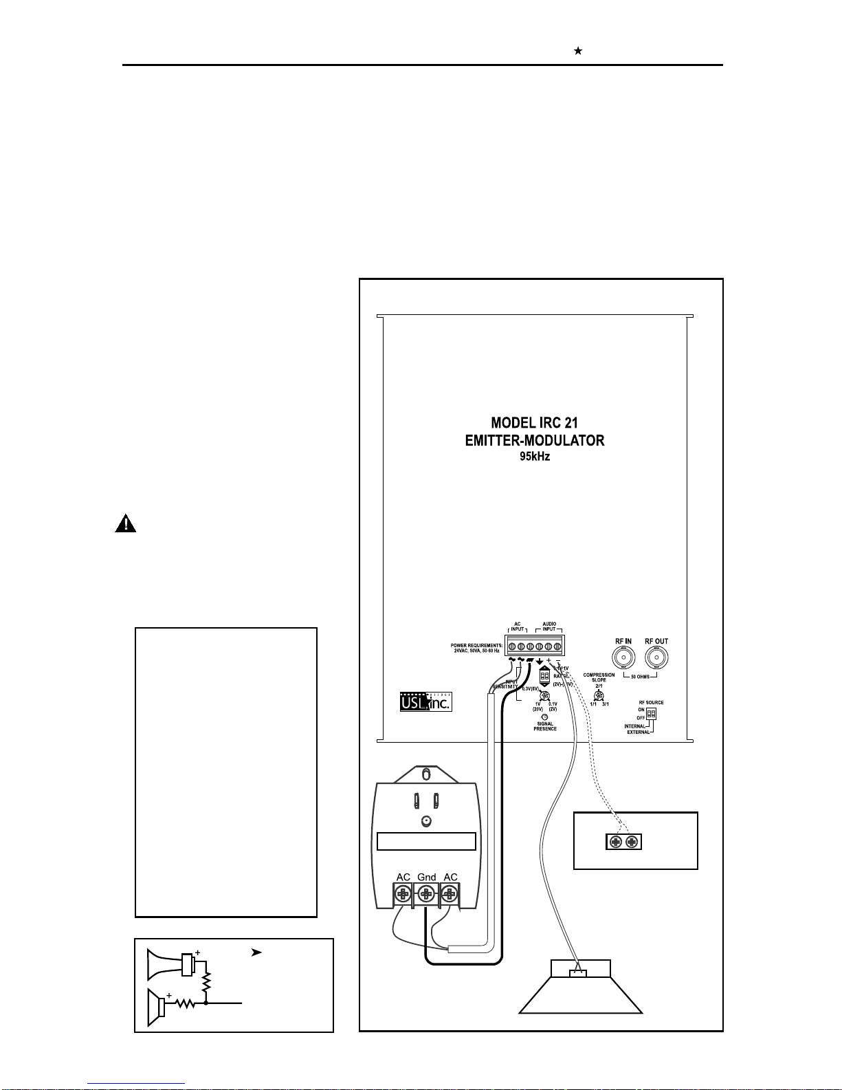
qPRELIMINARY LEVEL SETTING
If the system is to be used with a cinema sound system, simply run a standard
optical track 50% modulation loop in the projector (e.g., Dolby® or
Ultra Stereo®). Then adjust the IRC-21 Input Level Adjust trimpot so that as
the gain is increased, the green “Signal Present” LED just comes on.
If the system is being used with other sources such as tape, then adjust the
Input Level control so that a standard “0” reference level tape plays back so
the “Signal Presence” LED just begins to illuminate. With normal audio signal,
the LED should flash occasionally.
Note: The IRC-20 has an automatic shutoff circuit. The unit will
shut itself off after an thirty-minute absence of audio signal.
When the audio resumes, the panel will switch on instantly.
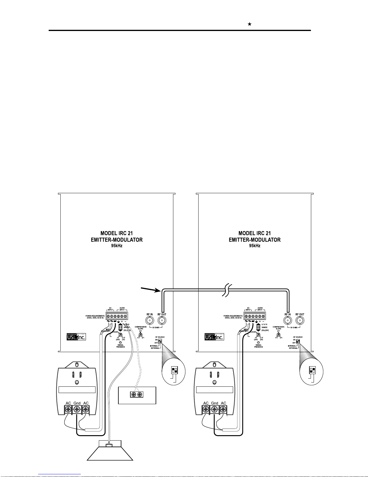
qMounting the Emitter/Modulator at the front of the auditorium
(See Figures F and G)Attach the supplied mounting bracket to the wall surface
and use the supplied screws to attach the bracket to the emitter. Allow free
airflow around the emitter and be sure to have at least eight inches clearance
from all surfaces, preferably more if at all possible. The rear panel is used as
a heat sink and the heat must be allowed to dissipate. The unit should be
mounted to the side of the screen/stage area, 12 to 15 feet above the audience’s
heads and pointed downward and into the seating area.
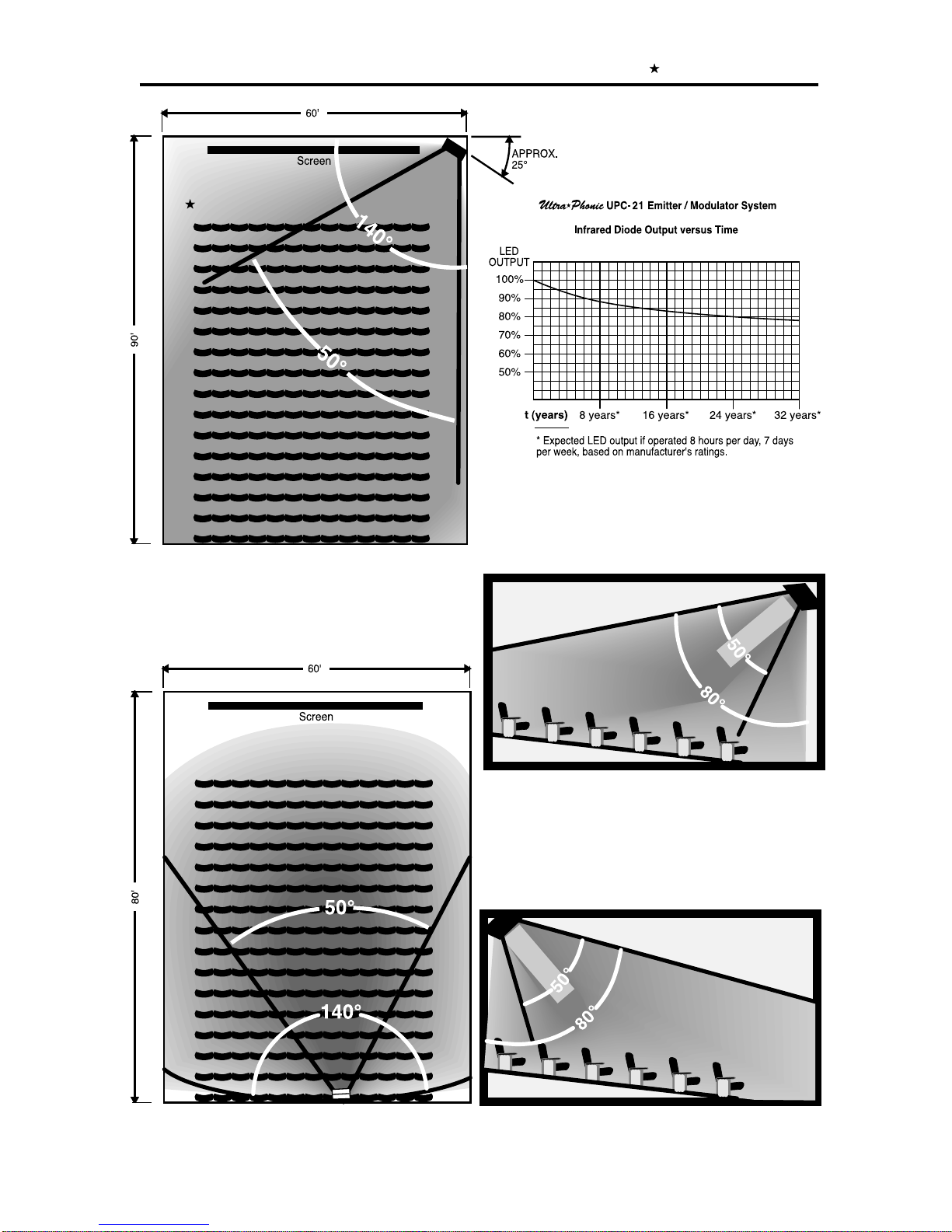
qMounting the Emitter/Modulator at the rear of the auditorium
(See Figures H and J)Attach the supplied mounting bracket to the wall surface
and use the supplied screws to attach the bracket to the emitter. Allow free
airflow around the emitter and be sure to have at least eight inches clearance
from all surfaces, preferably more if at all possible. The rear panel is used as
a heat sink and the heat must be allowed to dissipate. The emitter will cover
a maximum of 5500 square feet (60' X 84') and has a primary 50° (± 25°)
vertical and horizontal coverage angle, usually adequate for a 350-seat theatre.
Within 30 feet of the emitter the horizontal dispersion angle of emission
increases to over 140°. Within 18 feet of the emitter the vertical dispersion
angle of emission increases to 180°. The emitter can be mounted 12 to 15
feet above the audience’s heads. The unit should be pointed downward into
the seated area (Fig. G, J).
CAUTION: The rear panel may get quite warm to the touch. This is normal.

- 7 -
Fig. F - Front mounted emitter-top view
Fig. G - Front mounted emitter - side view
Fig. J - Rear mounted emitter - side view
Fig. H - Rear mounted emitter-top view
UPC-21 INSTRUCTION MANUAL Ultra Stereo Labs, Inc.

- 8 -
AC Power Pack
+ E
Cinema Processor Center Channel
Center Channel Speaker
OR
AC Power Pack
75 Ohm
Coaxial Cable
AN INSTALLATION USING TWO IRC-21S
Connect an IRP-20 power pack to each of the IRC-21s. From the unit receiving
the audio signal from a source, connect the RF OUT terminal to the RF IN
terminal of the second IRC-21 utilizing 75Ω Coaxial Cable.Apower pack MUST
be used for each IRC-21 so configured.
There is, theoretically, no limit to the number of IRC-21s from a single source
that you may connect in this way.
Within reason, distances between units is unlimited.
INTERNAL
EXTERNAL
RF SOURCE
ON
OFF
INTERNAL
EXTERNAL
RF SOURCE
ON
OFF
UPC-21 INSTRUCTION MANUAL Ultra Stereo Labs, Inc.

- 9 -
FACTS ABOUT
INFRARED TRANSMISSION SYSTEMS
The UPC-21 Infrared Transmission Systems use light emitting diodes frequency
modulated at 95kHz, the international standard.
The modulated waves radiate from the emitter panels primarily in straight lines.
Depending on the lightness of the wall color, some of this energy may be
reflected and bounce around the room. Infrared energy does not penetrate
walls. The modulated waves remain within the room where the emitter is
placed. This feature makes it perfect for use in multiplex theatre units and for
use in hotel and convention center meeting rooms and auditoriums.Additionally,
this characteristic of infrared transmission makes it ideal for meetings requiring
security of the signal.
USL, Inc. provides the following 95kHz headsets:
IRH-501 – an over-the-head receiver designed with a 360°
pickup.
IRH-701 – an under-the-chin receiver with a 180°
pickup.
UPC-21 INSTRUCTION MANUAL Ultra Stereo Labs, Inc.
Other manuals for UPC-21
1
Table of contents
Other Usl Transmitter manuals