manuals.online logo
Brands
  1. Home
  2. •
  3. Brands
  4. •
  5. Sealey
  6. •
  7. Test Equipment
  8. •
  9. Sealey VS925 User manual

Sealey VS925 User manual

INSTRUCTIONS FOR:
LAMBDA TESTER &
SIMULATOR
Thank you for purchasing a Sealey Product.
Manufactured to a high standard this product will, if used
according to these instructions and properly maintained,
give you years of trouble free performance.
IMPORTANT:PLEASE READ THESE INSTRUCTIONS CAREFULLY. NOTE
THE SAFE OPERATIONAL REQUIREMENTS, WARNINGS AND CAUTIONS.
USE THIS PRODUCT CORRECTLYAND WITH CARE FOR THE PURPOSE
FOR WHICH IT IS INTENDED. FAILURE TO DO SO MAYCAUSE DAMAGE
OR PERSONAL INJURYAND WILL INVALIDATE THE WARRANTY.
PLEASE KEEP INSTRUCTIONS SAFE FOR FUTURE USE.
Sole UK Distributor, Sealey Group, Bury St. Edmunds, Suffolk.
01284 757500
E-mail:
sales@sealey.co.uk
01284 703534
For Jack Sealey Ltd. Sole importer into the UK of Sealey Professional Tools.
Lambda Tester & Simulator
Model VS925
73/23/EEC Low Voltage Directive.
89/336/EEC EMC Directive.
93/68/EEC Marketing Directive.
14th September 2005
Declaration of Conformity
Signed by Mark Sweetman
Model: VS925
We, the sole importer into the UK, declare that the product listed here is in
conformity with the following standards and directives. The construction file
for this product is held by the Manufacturer and may be inspected, by a
national authority, upon request to Jack Sealey Ltd.
VS925 - 1 - 200905
General Maintenance: The Lambda tester is a sensitive electronic
instrument and should be treated as such. Avoid high temperatures,
mechanical shock and damp environments. Occasional inspection of
cables for damage and/or loose connections together with battery
replacement is the only required maintenance.
Battery Replacement: When the battery voltage is low the single
red LED in the ident panel will illuminate.
(1) Remove the battery lid on the rear of the instrument by sliding in
the direction of the arrow.
(2) Unplug the wire connector and install a new, good quality, alkaline
type PP3 9V battery. Replace the battery lid.
Specifications:
Power Supply: One 9V alkaline type PP3 battery.
Connectors: One wire-piercing clip and one black ground
clip.
Display: Output crossover of signal displayed
as a light path in the LED array.
Ident Panel: Indicators to identify heater supply, ECU
supply, open circuit LED, ground supply
and low battery indication.
Test Leads: Quality silicone leads able to withstand
high temperatures.
Enclosure: ABS.
Dimensions: 145mm x 80mm x 34mm.
Warranty 1 year. The warranty is invalid if the instrument
has been subject to misuse or abuse. The
warranty does not cover batteries or any other
materials that wear out during normal operation of
the instrument.
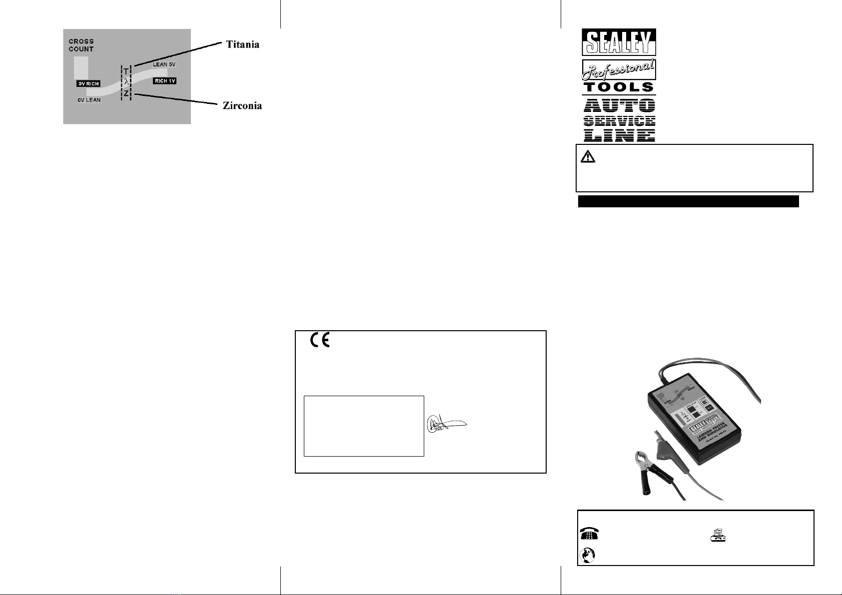
LAMBDA WINDOW:TITANIA SENSOR: RICH & LEAN
SIGNALS ARE REVERSED.
Normally a Lambda/O2sensor operating under acceptable
conditions will result in the display LED array illuminating
continuously from lean to rich then back again as shown in FIG 3.
This pattern is repeated constantly. If there is a fault with the
Lambda/O2sensor or ECU the normal pattern described above
will not occur and the activity in the LED array will be limited to
either the rich or lean sector of the display window, dependant on
the type of fault.
As a basic test to begin to identify the source of the fault, use the
simulation feature of the tester to introduce a RICH or LEAN
SIGNAL and observe whether this produces a change in the LED
activity present. By pressing +V (Titania, press 0V) the tester
will transmit a RICH signal to the ECU.
If the circuit is functioning correctly the mixture will be weakened
and the result should be apparent by a decrease in the engine
speed occurring. Ideally, a four-gas analyser should be used to
verify that the mixture strength varies in response to the false
signals introduced. No reaction would suggest a wiring/connection
problem or faulty ECU. Faulty fuelling, faulty ignition or faulty
management sensors (located on the engine) could also produce
the same effect. If the response to the simulated signals IS
detected, then the Lambda/O2sensor should be inspected,
cleaned and tested and substitution or replacement undertaken as
necessary.
In some management systems a simulated signal may flag into
the systems memory and be shown as a fault code when
checked with a code reader. Some management systems also
contain a "limp home device" which activates when the Lambda
sensor fails. The ECU will input a firm value signal of approx.
500mV to the sensor to allow the vehicle to be driven at low
speeds. This condition will show on the display area of the tester
when either the first or the second LED is lit constantly in the
Lambda window.
1. SAFETY INSTRUCTIONS
pWARNING! Ensure Health and Safety, local authority and
general workshop practice regulations are adhered to when
using tools.
7DO NOT use tester if damaged.
3Maintain tester in good and clean condition for best and
safest performance.
3Ensure that a vehicle which has been jacked up is
adequately supported with axle stands.
3Wear approved eye protection. Afull range of personal safety
equipment is available from your Sealey dealer.
3Wear suitable clothing to avoid snagging. Do not wear
jewellery and tie back long hair.
3Account for all tools and parts being used and do not leave
any on or near the engine.
NOTE: It is our policy to continually improve products and as such we reserve
the right to alter data, specifications and component parts without prior notice.
IMPORTANT: No liability is accepted for incorrect use of this equipment.
WARRANTY: Guarantee is 12 months from purchase date, proof of which
will be required for any claim.
INFORMATION: For a copy of our latest catalogue and promotions call us
on 01284 757525 and leave your full name and address, including
Fig 3
www.sealey.co.uk
In the case of 2, 3 or 4 wire sensors the indicator panel will
identify which wire you are connected to (refer to Fig 1). Reading
from the top of the panel, if the first LED lights up this indicates
the clip is connected to the heater supply voltage. If the second
LED lights up this is an indication of connection to the ECU 5V
supply, (applicable in the case of Titania sensor, where fitted).
The open circuit LED lights up when the tester is first switched on
but not connected to any of the sensor wires, this is an open
circuit indicator. This LED will stay lit if a bad connection is made
to any of the sensor wires, it will go out if a good connection is
made, one of the other lights will then be lit. When connection to
the signal wire is made the lights on the vertical display will go
out, then the display LED array In the Lambda window will
activate.
Agood sensor will show movement across the light path and will
illuminate the LEDs in or across the "Lambda Window" (see
diagram over) Once the LED array is activated, ignore any
occasional flickering of the indicator lights on the panel to the left.
If connected in default (ZIRCONIA) mode, but only the top 2 lights
on the right hand side are flickering, this could indicate a Titania
sensor. Leaving the unit connected to the signal wire, switch the
unit off and follow instructions for selecting Titania sensor. If the
lights then show movement across the Lambda window (display
LED), this would then indicate a Titania sensor on the vehicle.
Fig 1
Indicator Panel:
NOTE: Cross count is disabled - it only indicates connection to Titania
sensors by displaying ''t'' in the cross count box.
One of the unique features of the Lambda Tester is its ability to indicate
to which wire on the Lambda sensor the unit is connected. This tells the
operator which is the signal wire for measuring the Lambda output and
also identifies the presence of the heater supply voltage (where
applicable) and the sensor ground condition. Refer to Fig 1.
Introduction
The Lambda Tester is designed to measure the crossover changes
which occur in the closed loop control system. The product will
analyse both Zirconia and Titania type sensors.
This analyser can simulate the sensor signals to the ECU to verify
acceptance of the signals and confirm that the ECU acts upon
them.
The unit allows the operator to verify which wire the instrument is
connected to, a feature which is particularly useful when working
with heated sensors.
Features
p
p
Tests 1, 2, 3 and 4 wire sensors.
p
p
Tests heated and non-heated sensors.
p
p
Unique ident panel identifies which wire the instrument is
connected to i.e. ground, heater or ECU supply (where
applicable). Open circuit indicator identifies bad connection.
p
p
Rich or lean simulation to check ECU reaction.
p
p
Wire piercing clip for ease of connection.
p
p
Unique LED light path displays the crossover signals of the
Lambda sensor.
p
p
Runs off internal 9V alkaline battery with indicator to show
when battery is running low.
p
p
One year limited warranty.
p
p
Sealed control switches for workshop environment.
p
p
Durable ABS enclosure.
Warnings
Failure to follow the warnings indicated here may result in personal
injury and/or damage to property and the instrument. Misuse or
improper application of the instrument will invalidate the warranty.
The instrument is designed for analysing Lambda/O2sensor
systems and simulation of the Lambda signal output to the ECU. It
is not intended for use on any other vehicle systems. Always wear
the correct eye protection and keep hands and clothing from
coming into contact with rotating engine parts.
Lambda/O2sensors are located within the exhaust system, when
working on them be well aware of extremes of heat.
Ensure the handbrake is applied on the vehicle under test and if
the vehicle has automatic transmission, put it in the PARK
position.
Always ensure there is adequate ventilation when working with
engine running. Emissions of carbon monoxide (if inhaled) can
cause serious damage to health.
VS925 - 1 - 200905
Operating Instructions:
NOTE: DEFAULT SETTING IS ZIRCONIA. TITANIA SENSOR MUST
BE MANUALLY SELECTED (see below) & THE RICH & LEAN
VALUES ARE REVERSED.
SELECTING TITANIA: Before switching on, press either +V or 0V
button, keep pressed down whilst switching unit ON, then release.
Refer to Fig 2. This puts the unit into Titania mode, confirmed by ''t''
appearing in the cross count box at the top left of the unit in Fig 3.
NOTE: The engine must be at normal operating temperature and
running at 1500-2000RPM to test the O2sensor.
The tester is fitted with a wire-piercing clip allowing it to pierce the
sensor wires without damage, (the insulation congeals back to its
original state after removal).
Switch on the tester by pressing the ON button at Fig 2. Connect the
black ground clip to a good chassis ground, or the negative terminal of
the vehicles battery. Connect the wire-piercing clip to any of the sensor
wires: the tester is capable of testing 1, 2, 3, and 4 wire sensors.
Fig 2

Other Sealey Test Equipment manuals

Sealey CV0011 User manual

Sealey

Sealey CV0011 User manual

Sealey TA4000 User manual

Sealey

Sealey TA4000 User manual

Sealey VS4022.V2 User manual

Sealey

Sealey VS4022.V2 User manual

Sealey VS0031.V3 User manual

Sealey

Sealey VS0031.V3 User manual

Sealey TST22 User manual

Sealey

Sealey TST22 User manual

Sealey PPHY User manual

Sealey

Sealey PPHY User manual

Sealey VSE211.V4 Firmware update

Sealey

Sealey VSE211.V4 Firmware update

Sealey VS0275.V2 User manual

Sealey

Sealey VS0275.V2 User manual

Sealey TA319.V2 User manual

Sealey

Sealey TA319.V2 User manual

Sealey VS4021 User manual

Sealey

Sealey VS4021 User manual

Sealey CV0011.V2 User manual

Sealey

Sealey CV0011.V2 User manual

Sealey VS0275 User manual

Sealey

Sealey VS0275 User manual

Sealey BT101 User manual

Sealey

Sealey BT101 User manual

Sealey Auto Service Line VS2030 User manual

Sealey

Sealey Auto Service Line VS2030 User manual

Sealey VS001.V3 User manual

Sealey

Sealey VS001.V3 User manual

Sealey VS211.V2 User manual

Sealey

Sealey VS211.V2 User manual

Sealey MC105 User manual

Sealey

Sealey MC105 User manual

Sealey BT91/3 User manual

Sealey

Sealey BT91/3 User manual

Sealey VSE3158 User manual

Sealey

Sealey VSE3158 User manual

Sealey BT91/11 User manual

Sealey

Sealey BT91/11 User manual

Sealey AUTO SERVICE VS401 User manual

Sealey

Sealey AUTO SERVICE VS401 User manual

Sealey TST22 User manual

Sealey

Sealey TST22 User manual

Sealey BT91/7PF User manual

Sealey

Sealey BT91/7PF User manual

Sealey VS0014 User manual

Sealey

Sealey VS0014 User manual

Popular Test Equipment manuals by other brands

Mabit SmartControl instruction manual

Mabit

Mabit SmartControl instruction manual

Anritsu MT8860C Operation manual

Anritsu

Anritsu MT8860C Operation manual

RND 320-KEL Series user manual

RND

RND 320-KEL Series user manual

Platinum Tools NETXPERT XG2 manual

Platinum Tools

Platinum Tools NETXPERT XG2 manual

Tektronix MSO70000C/DX Technical reference

Tektronix

Tektronix MSO70000C/DX Technical reference

Wetekom VT-603 instruction manual

Wetekom

Wetekom VT-603 instruction manual

Keithley SourceMeter 2425 Service manual

Keithley

Keithley SourceMeter 2425 Service manual

FIS Thunder Bolt Operation manual

FIS

FIS Thunder Bolt Operation manual

CS Instruments LD 300 instruction manual

CS Instruments

CS Instruments LD 300 instruction manual

Instron 6800 Series Operator's guide

Instron

Instron 6800 Series Operator's guide

Seals Nidec DT-366 Operation manual

Seals

Seals Nidec DT-366 Operation manual

Fluke 80T-150U instruction sheet

Fluke

Fluke 80T-150U instruction sheet

IVRA BTS c-Go instruction manual

IVRA

IVRA BTS c-Go instruction manual

Viavi OneAdvisor-1000 manual

Viavi

Viavi OneAdvisor-1000 manual

Platinum Tools Fault Trapper TFT100 quick start guide

Platinum Tools

Platinum Tools Fault Trapper TFT100 quick start guide

Fluke CableAnalyzer DSX-500 Getting started guide

Fluke

Fluke CableAnalyzer DSX-500 Getting started guide

EUTECH INSTRUMENTS PCSTestr35 quick guide

EUTECH INSTRUMENTS

EUTECH INSTRUMENTS PCSTestr35 quick guide

WHALETEQ SEEG 100E user manual

WHALETEQ

WHALETEQ SEEG 100E user manual

manuals.online logo
manuals.online logoBrands
  • About & Mission
  • Contact us
  • Privacy Policy
  • Terms and Conditions

Copyright 2025 Manuals.Online. All Rights Reserved.