ACCESSORIES
CODE DESCRIPTION QTY
FCFP FRONT COLUMN FITTING 2
CCFP CORNER COLUMN FITTNG 4
CFP COLUMN FITTING 18
DCBFP DOOR COLUMN BOTTOM FITTING 2
CBFP CENTER BAND FITTING 10
BS BOTTOM SLIDER 4
DH DOOR HANDLE 2
FC RIDGE END CAP 2
TC TOP CORNERS 4
TS TOP SLIDER 4
PPG ROOF PLUG WITH WASHER 54
PIN ROOF PIN 54
PW PLASTIC WASHERS 318
PC PLASTIC SCREW COVER 109
WHG HOOK 1
EDP EDGING PROFILE 1
S1 SHEET METAL SCREW 548
DIA. 4.2mm.x16.0mm. (5/32”x5/8”)
S3 MACHINE SCREW with NUTS 84
M4x10.0mm. (5/32”x3/8”)
S7 SHEET METAL SCREW 76
DIA. 4.2mm.x10.0mm. (5/32”x3/8”)
Note: Check all parts prior to installation.
CODE DESCRIPTION QTY
FC1AP FOUNDATION ‘U’ CHANNEL 2
FC2AP FOUNDATION ‘U’ CHANNEL 2
FC3AP FOUNDATION ‘U’ CHANNEL 2
FC4AP FOUNDATION ‘U’ CHANNEL 2
FCCP FOUNDATION ‘U’ CHANNEL 4
BLAP BASE BAR BACK LEFT 1
BRAP BASE BAR BACK RIGHT 1
BS1AP BASE BAR SIDE FRONT LEFT / BACK RIGHT 2
BS2AP BASE BAR SIDE FRONT RIGHT / BACK LEFT 2
BBFP BASE BAR FRONT 2
ECAP ENTRANCE TAPER CHANNEL 1
COLP COLUMN LONG 16
COSP COLUMN SHORT 2
DCLP DOOR COLUMN PROFILE LEFT 1
DCRP DOOR COLUMN PROFILE RIGHT 1
CS COLUMN SUPPORT 4
CB1P CENTER BAND FRONT 2
CB2P CENTER BAND SIDE FRONT 2
CB3P CENTER BAND SIDE FRONT 2
CB4P CENTER BAND MIDDLE 9
SLAP SLIDING CHANNEL LEFT 1
SRAP SLIDING CHANNEL RIGHT 1
SJP SLIDING CHANNEL JOINT 1
SCAP SLIDING CHANNEL COVER 2
AS1AP TOP ANGLE SIDE FRONT LEFT / BACK RIGHT 2
AS2AP TOP ANGLE SIDE FRONT RIGHT / BACK LEFT 2
ABLAP TOP ANGLE BACK LEFT 1
ABRAP TOP ANGLE BACK RIGHT 1
SB1AP SUPPORT BRACKET FRONT RIGHT/BACK LEFT 2
SB2AP SUPPORT BRACKET FRONT LEFT/BACK RIGHT 2
SB3AP SUPPORT BRACKET LONG FRONT RIGHT/BACK LEFT 2
SB4AP SUPPORT BRACKET LONG FRONT LEFT/BACK RIGHT 2
FBS FACIA BRACKET SUPPORT 8
FSLAP FACIA SUPPORT LEFT 2
FSRAP FACIA SUPPORT RIGHT 2
RS1AP ROOF SUPPORT 4
RS2AP ROOF SUPPORT 4
RS4AP ROOF STRUCTURE 6
RF1AP ROOF FLASHING FRONT RIGHT/BACK LEFT 2
RF2AP ROOF FLASHING FRONT LEFT/BACK RIGHT 2
RFSAP ROOF FLASHING SIDE 4
DSTAP DOOR PANEL STRIP TOP 2
DSBAP DOOR PANEL STRIP BOTTOM 2
DMSAP DOOR PANEL MIDDLE SUPPORT 2
DVSP DOOR PANEL VERTICAL SUPPORT 2
DSP DOOR STOPPER VERTICAL 2
HS HINGES SUPPORT 1
HAS HIGHT ADJUSTABLE SUPPORT 1
WP1A FRONT WALL PANEL LEFT 1
WP2A FRONT WALL PANEL RIGHT 1
WP3A CORNER WALL PANEL 4
WP4A WALL PANEL 9
FLAP FACIA PANEL LEFT 2
FRAP FACIA PANEL RIGHT 2
RP1AP ROOF PANEL 2
RP2AP ROOF PANEL 1
RP3AP ROOF PANEL 2
RP4AP ROOF PANEL 2
RP2AG ROOF PANEL 1
RPWG ROOF PANEL WINDOW 1
RC1P RIDGE COVER 1
RC2P RIDGE COVER 3
DL1AP DOOR PANEL LEFT 1
DL2AP DOOR PANEL LEFT 1
DR1AP DOOR PANEL RIGHT 1
DR2AP DOOR PANEL RIGHT 1
VBCS1 VENTILATION BLOCKING COVER SIDE-1 6
VBCS2 VENTILATION BLOCKING COVER SIDE-2 2
VBCF VENTILATION BLOCKING COVER FRONT/BACK 7
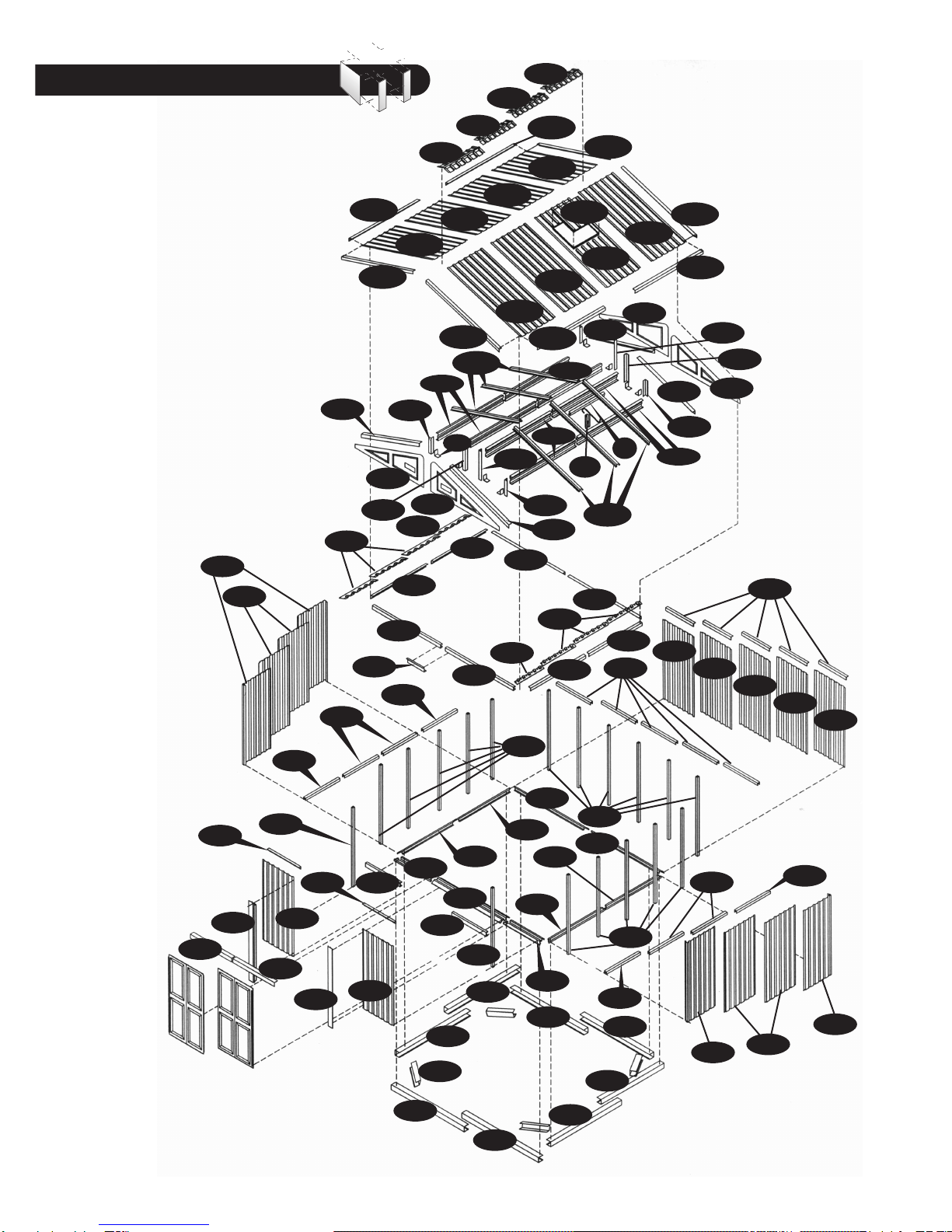
Parts List
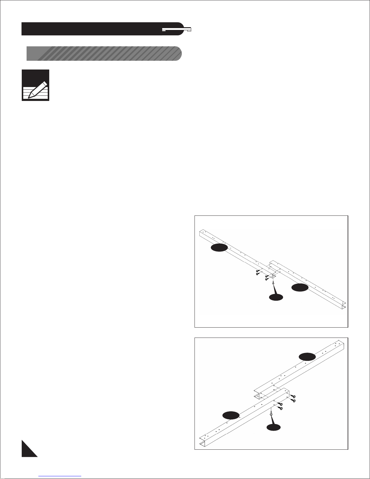
BASE BAR
(BLAP, BRAP, BS1AP, BS2AP)
PROFILES
IMPORTANT: USE HAND GLOVES TO PREVENT INJURY.
TOP ANGLE BACK
(ABLAP, ABRAP)
BASE BAR FRONT
(BBFP)
DOOR COLUMN
PROFILE LEFT
(DCLP)
ENTRANCE TAPER CHANNEL
(ECAP)
DOOR COLUMN
PROFILE RIGHT
(DCRP)
SLIDING CHANNEL COVER
(SCAP) TOP ANGLE SIDE
(AS1AP, AS2AP)
SLIDING CHANNEL
(SLAP, SRAP) SLIDING CHANNEL
SUPPORT
(SJP)
ROOF SUPPORT
BRACKET
(SB1AP, SB2AP)
ROOF FLASHING
(RF1AP, RF2AP, RFSAP)
ROOF SUPPORT
(RS1AP, RS2AP)
DOOR PANEL VERTICAL
SUPPORT
(DVSP)
DOOR STOPPER
VERTICAL
(DSP)
DOOR PANEL MIDDLE
SUPPORT
(DMSAP)
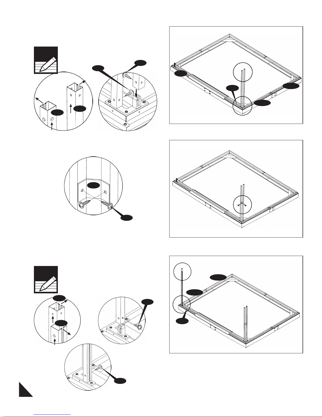
COLUMN
(COLP, COSP)
CENTER BAND
(CB2P, CB3P, CB4P) (HS) CENTER BAND FRONT
(CB1P)
PLASTIC WASHER
(PW)
TOP SLIDER
(TS)
TOP CORNERS
(TC)
DOOR HANDLE
(DH)
BOTTOM SLIDER
(BS)
CENTER BAND FITTING
(CBFP)
CORNER COLUMN FITTING
(CCFP)
COLUMN FITTING
(CFP)
ROOF PLUG
(PPG)
ROOF PIN
(PIN)
RIDGE END CAP
(FC)
MACHINE SCREW WITH
NUT (S3)
SHEET METAL SCREW
(S1, S7) FACIA SUPPORT
(FSLAP, FSRAP,
SB3AP, SB4AP)
DOOR PANEL STRIP
(DSTAP, DSBAP)
ROOF SUPPORT
(RS4AP) (HAS)
PLASTIC SCREW COVER
(PC)
COLUMN SUPPORT
(CS)
FACIA BRACKET
SUPPORT (FBS)
FRONT COLUMN FITTING
(FCFP) DOOR COLUMN
BOTTOM FITTING
(DCBFP)
HOOK (WHG)‘U’ CHANNEL
(FC1AP, 2AP, 3AP, 4AP
FCCP)