USR IOT USR-K7 User manual

Super Port User Guide www.usriot.com
Page1/34
Serial to Ethernet converter (Super Port)
(USR-K7)
File version: V1.0.0

Super Port User Guide www.usriot.com
Page2/34
Contents
Serial to Ethernet converter (Super Port) ..........................................................................................1
1. Introduction...............................................................................................................................3
1.1. Overview .......................................................................................................................3
1.2 Features...............................................................................................................................3
1.2. Basic parameters ...........................................................................................................4
1.3. Order information..........................................................................................................5
1.4. Electrical characteristics ................................................................................................5
2. Module Test...............................................................................................................................5
2.1. Hardware connection ....................................................................................................5
2.2. Login..............................................................................................................................7
2.3. Default parameter test ..................................................................................................8
2.4. Data transmission text...................................................................................................9
3. Work mode..............................................................................................................................10
Diagram 3-2 work mode AT commend ....................................................................................11
3.1. UDP mode ...................................................................................................................11
3.2. TCP Client ....................................................................................................................12
3.3. UDP Server mode ........................................................................................................13
3.4. TCP Server mode .........................................................................................................15
3.5. Httpd Client mode .......................................................................................................16
4. Hardware.................................................................................................................................18
4.1. Hardware.....................................................................................................................19
4.2. Pin definition ...............................................................................................................19
4.3. Size ..............................................................................................................................21
4.4. Connection diagram ....................................................................................................22
4.5. LED ..............................................................................................................................22
4.6. RJ45 interface ..............................................................................................................22
5. Parameters configuration ........................................................................................................23
5.1. Setup software configure parameters .........................................................................23
6. Specific functions.....................................................................................................................28
6.1. Modbus RTU to Modbus TCP.......................................................................................28
6.2. Heartbeat package ......................................................................................................30
6.3. Registration package....................................................................................................30
6.4. Web printing................................................................................................................31
6.5. Customize webpage.....................................................................................................32
7. Contact us................................................................................................................................33
8. Modified history ......................................................................................................................34

Super Port User Guide www.usriot.com
Page3/34
1. Introduction
1.1.Overview
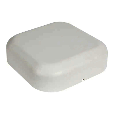
Super port module USR-K7 is a new serial Ethernet module. It is a module that can realize
data transmission between the network and TTL serial ports.This module is equipped with ARM
cortex-m4 processor, which has the advantages of low power consumption, fast speed and high
stability.
In terms of volume, the width of the device is equal to the common RJ45 port, and the length
is less than twice the length of the common network port, with the industry-leading ultra-small
volume, and the current is only 130mA when working at full speed.
This product is developed on the basis of the hardware and software of serial to ethernet M4
series.The internal integration of TCP/IP protocol stack, users can use it to complete the embedded
device networking function easily, saving the development process of human, material and
development cycle, so that products can be faster into the market, enhance competitiveness.
This product has been tested rigorously and has been successfully used in Banks, highways,
large corporate networks, busy webcam networks and complex network environments such as
fiber-optic to Ethernet.
1.2 Features
1. New Cortex-M4 kernel, industrial working temperature range(-40~85℃), elaborate
optimization TCPIP protocol stack, stable and reliable.
2. Auto-MIDX function, discretionarily connect cross-over or direct network cable,
automatic switching.
3. Support TCP Server, TCP Client, UDP, UDP Server, HTTPD Client, websocket, various of
Ethernet protocols.
4. A built-in web page, also parameter setting via web, can customize web pages for users.
5. Reserve 485 enable pins.
6. Support RTS/CTS hardware flow control and Xon/Xoff software flow control
7. Support USR-VCOM
8. Serial port highest baud rate from 600bps to 1024Kbps, and support five calibration
methods like None, Odd, Even, Mark, Space.
9. Support Modbus gateway, the industrial site is convenient to use.
10. Support Reload, hardware factory data reset
11. RJ45 status indicator light, RJ45 interface built-in isolation transformer, 1.5KV isolation.
12. Unique MAC address, and can customize MAC address.
13. Support upgrade firmware via network, support DNS and DHCP automatic access to IP.
14. Support keepalive, detect a dead link quickly and make connection more stable.
15. Support name and pass word, login page and set network more safety.
16. Support Websocket function, realize net and serial bi-transmission between net and
serial.

Super Port User Guide www.usriot.com
Page4/34
1.2.Basic parameters
category
parameters
value
Hardware
parameters
Work volt
DC 3.0~3.6 V,(the best is3.3V)
Work current
130mA@3.3V
Net port
specification
RJ45、10/100Mbps、adopted to both cross and direct
connection
Packaging from
Pin type packaging
Serial port baud
rate
600~1M(bps)
Software
parameters
Network protocol
IP、TCP、UDP、DHCP、DNS、HTTP、ARP、ICMP、Web
socket
IP access way
Static IP、DHCP
Domain name
resolution
Support
User configure
Software configure, webpage configure,
AT commend configure
Single transparent
transmission
TCP Server/TCP Client/UDP Server/UDP Client
Modbus
Modbus gateway: Modbus RTU to TCP, Modbus Polling
Webpage to serial
port
Web-Socket: web-page to serial port
Httpd Client
Support
Class RFC2217
Support
Customize
webpage
Support
Web caching
Sent:16Kbyte;Sent:16Kbyte;
Serial port caching
Sent:2Kbyte;Sent:2Kbyte;
Average
transmission delay
In LAN<10ms
Software kit
Virtual.com, serial port, USR-Cloud, parameter configure
Others
Identification
CE、FCC、ROHS ( Will be got in June)
Level class
1.5KV EMC
size
35.0x19.39x18.25 mm(L*W*H)
Work tempt
-40~85c
Store tempt
-40~105c
Work humidity
5%~95% RH(no condensation)
Store humidity
5%~95% RH(no condensation)
Diagram 1-1 Electrical parameters

Super Port User Guide www.usriot.com
Page5/34
1.3.Order information
Type
Part Numbers
Electric interface
Super Port
USR-K7
1*UART,1*RS232 built-in RJ45
Diagram 1-2 Order information
Configuration method: serial port AT command/network AT
command/webpage/Software
Power supply: DC 3.3V only
Inches: 33.02 x 19.01 x 19.15 (mm, include the Shrapnel)
Work temperature: -40~+85°C
Store temperature: -40~85°C,5~95%RH
Buffer of comm port: 2K byte
Buffer of Network: 16K byte
1.4.Electrical characteristics
All the data is get at temperature 25C, network cable plug in, max data transmission (10ms,
20 byte, sending data constantly).
Diagram 1-3 Electrical information
2. Module Test
If you have any question, please contact us the in the client support center:
http://h.usriot.com/index.php?c=frontTicket&m=sign
2.1.Hardware connection
The picture below is a serial device server of USR-K7.It have 1 UART to Ethernet interface.
Input Voltage range
Current consumption at
3.3V
USR-K7
DC3.3V
130mA

Super Port User Guide www.usriot.com
Page6/34
Diagram 2-1 Development Kit
Power the development kit board with DC5V adaptor(make sure you can supply at least
200mA current at DC5V, USR-K7 only accept DC3.3V, but since we are using a eval board, DC5V will
do)
Connect K7's RJ45 to PC directly with network cable(No need to distinguish cross or direct
connect cable), or connect the module and PC via switch or router and set the PC's ip address to
192.168.0.201 (must be a format of 192.168.0.xxx), net mask 255.255.255.0.
Connect development board's RS232 and PC's comm port together, with a standard
male-female extend cable(default no-cross-over cable).
Here is USR-K7's default net configuration,
IP address: 192.168.0.7
Subnet mask: 255.255.255.0
The default gateway: 192.168.0.1
To text the transmission between serial and network, we put the k7 to evaluation board, and
connect evaluation board and computer via serial port or USB, connect net port of K7 and PC,
after the hardware connection is tested to be error-free, connect the power adapter we
distributed to power the K7 evaluation board. The connection diagram is shown in the figure
below:

Super Port User Guide www.usriot.com
Page7/34
Diagram 2-2 Hardware connection
2.2.Login
The default IP address of USR-K7 is 192.168.0.7. Open your web browser and enter this IP to
connect to USR-K7 for configuration. Before that, please assign a static IP address of your PC in the
same network segment as module’s from 192.168.0.2 to 192.168.0.24 range.
User name and password is ‘admin’ .
User name and password are both “admin”, this can be modified after login into the system.
Default user name: admin
Default password: admin
After you login, you can see webpage as follow,
Diagram 2-3 webpage after login
Current Status: the module's name, current IP, firmware revision, and other status
information
Local IP Config: the module's IP address, submask and gateway parameter
TTL1: the module's serial to Ethernet parameter
Web to Serial: web to serial data transparent
Misc Config: some parameter such as user name and password parameter

Super Port User Guide www.usriot.com
Page8/34
Reboot: user can reboot/restart module from here
Diagram 2-4 webpage -TTL1
2.3.Default parameter test
Use test program USR-TCP232-Test to make the testing of transmitting and receiving.
The left side is serial port, keep the same parameters as PC (Here is default settings).
The right side is the network side, protocol sets as TCP Client, server IP sets as 192.168.0.7,
port 23.
By default, USR-K7 works as TCP Server ,port 23.
This illustration shows the 10 ms two-way simultaneous automatically transmit screen shots.
As the allocated memory of the display control is limited, in order to test large amount of data
transceiver, here will suspend the receive display, only statistical data. Below is the effect after
testing for a few hours, and transmitting millions of bytes. Stable and reliable, without a byte loss.

Super Port User Guide www.usriot.com
Page9/34
Diagram 2-5 default working mode communication
Chart 1 default parameters
project
content
User name
admin
Password
admin
IP address
192.168.0.7
K7 subnet mask
255.255.255.0
K7 default gateway
192.168.0.1
K7 port1 default mode
TCP Server
K7port1 default interface
23
Serial port baud rate
115200
Serial port parameters
None/8/1
Diagram 2-6 Default parameters
2.4. Data transmission text
After above steps, you can do bi-communication between serial port and Ethernet. Step are
as follows:
1) Open the ‘USR-TCP232-Test.exe’, connect the hardware.
2) Choose the TCP Client mode in net setting, put in 192.168.0.7 in server IP address, and the port
number is 23. Click connection to built TCP link. Serial port baud rate is 115200, serial port
parameters is None/8/1, then click OPEN to open the serial port.
Now we can text the data transmit between serial port and network. The data flow from serial
port to network is: computer serial port ->K7 serial port ->K7 Ethernet port -> computer network;

Super Port User Guide www.usriot.com
Page10/34
The data flow from network to serial port is: computer network ->K7 Ethernet port ->K7 serial port
-> computer serial port.
Detail are as follows:
Diagram 2-7 Default parameters text
3. Work mode
There are 5 work modes for K7, including UDP Client、TCP Client、UDP Server、TCP Server、
Httpd Client. You can configure it by webpage and setting software. Detail are as follows:
Diagram 3-1 Work mode setting example
Refer to AT commend:
Name
description
AT+SOCKA1
Set K7 SOCKA communication protocol /Destination
IP/Destination port
AT+SOCKB1
Set K7 SOCKB communication protocol /Destination
IP/Destination port

Super Port User Guide www.usriot.com
Page11/34
Diagram 3-2 work mode AT commend
3.1.UDP mode
In UDP mode, after power on, module listen on specific port.
When received data from this udp port, send it to serial port;otherwise, when data is received
from serial port, send it to ethernet.
The assist software can be download from link below:
http://www.usriot.com/Download/199.html
Diagram 3-4 UDP mode communication test
Note:
1) local port and remote port can be different.
2) Max UDP send length(ethernet to serial) is 1472 bytes. If you want to send more than 1472
Bytes, please div it into shorter packet.

Super Port User Guide www.usriot.com
Page12/34
3.2.TCP Client
Diagram 3-5 TCP Client mode instructions
1)TCP Client provide Client connection to TCP network service. It can initiate a connection and
connect to the server to realize the transmission between serial port data and server data.
According to related provisions of TCP protocol,TCP client makes a distinction between connection
and disconnection to ensure the exchanging of data. Usually, it is the most common form of
network communication which adopted to data interaction between devices and servers.
2)This mode have a function that identify connection exceptions actively. After connected, there
will be about 15s internal to sent KeepAlive. If there is an abnormal interruption of the connection,
etc., it will be detected immediately and prompt K7 to break the original connection and
reconnect
3)When K7 try to connect server as TCP Client, the local port is 0, each time a link is initiated on
a random port.
4)This mode supports the synchronous baud rate function, transmission cloud and Modbus TCP
function of USR.
5)In the same LAN, if K7 is set as static IP, please set the IP of K7 as gateway IP and correctly set
the gateway IP address, otherwise normal communication will not be possible.
6)Note: KeepAlive function, sync baud rate function, pass-through cloud function, Modbus TCP
function are described in detail below.

Super Port User Guide www.usriot.com
Page13/34
Use USR-TCP232-Test,
Diagram 3-6 TCP Client communication test
3.3.UDP Server mode

Super Port User Guide www.usriot.com
Page14/34
1)UDP Server does not verify the source IP address on the basis of ordinary UDP. After each UDP
packet is received, the target IP is changed to the data source IP and port number. When sending
data, it is sent to the latest communication IP and port number.
2)This pattern is usually used for data transmission scenarios where multiple network devices
need to communicate with the module and do not want to use TCP due to the high speed and
frequency.
Like the socket UDP server in PC API. Many to one data transfer supported, the data from
UART part will be transformed to the last UDP packet’s address.
Here show 2 UDP client communicate with server, server send data to the last client
communicates with it.
Diagram 3-8 Client 1 <-> server

Super Port User Guide www.usriot.com
Page15/34
Diagram 3-9Client 2 <-> server
3.4.TCP Server mode
1)In TCP server mode, module listens to the local port, accepts connection requests and
established connection for data communication. When the module port receive the data, it will
sent data to all the client devices connected to module. And then, TCP server mode also has
KeepAlive function to monitor the integrity if connection.

Super Port User Guide www.usriot.com
Page16/34
2)Usually used for communication with TCP client in LAN, it is suitable for scenarios where there
are no servers on the LAN and multiple computers or mobile phones are requesting data from the
module. As the TCP client ,there are distinctions between connection and disconnection to ensure
the reliable exchange of data.
3)This mode supports synchronous baud rate (RFC2217) and Modbus TCP function of USR.
4)When K7 work as a TCP server, its max link number is 8.(later expanded to 32)
TCP Server mode have 2 parameters: max link number and link type
1. max link number: 1 ~ 8;
Diagram 3-11 Webpage configuration
3.5.Httpd Client mode
In this mode, user’s terminal devices can sent question data to pointed HTTPD server, and
then K7 accepts the data form HTTPD Server, analyze data and sent the results to serial port.
Users needn’t pay attention to the data conversion process between the serial port and the
network, and only needs simple parameters set to realize the data request from the serial port
device to the HTTP Server.
If the data haven’t pass the K7 and server haven’t disconnect active ,the module will
automatically disconnect.

Super Port User Guide www.usriot.com
Page17/34
The detailed working diagram and setup example diagram of Httpd Client mode are as
follows.
This function is easier used for web page developer. We establish one web server page, add
this:[<?php echo $_GET['data']; ?>]
Means we can GET data from HTTP client’s request. Open this URL:
test.usr.cn/1.php?data=12345, the web page is downbelow, we can see that the web server have
got the data(12345),
Diagram 3-13 Request test.usr.cn/1.php? and upload data
Then we take another way, set USR-K7 module Work mode HTTPD Client, Target address
test.usr.cn, remote port 80.

Super Port User Guide www.usriot.com
Page18/34
Diagram 3-14 configure HTTPD Client
Open USR-TCP232-Test, and type in a string such as "12345", then send via comm port to
USR-K7, and see the response from test.usr.cn .
In the response, all the data returned, but the http header from server will be returned, too.
the user may need to parse this to get your data.
4. Hardware
About the new PCB libraries file, we can download it from website http://www.usriot.com/Download/221.html .

Super Port User Guide www.usriot.com
Page19/34
4.1.Hardware
Diagram 4-1 USR-K7
Mechanical dimesion: 33.02 x 19.01 x 19.15 (mm, include the Shrapnel)
3.3V power input
1 * UART (TTL, 3.3V)
support hardware flow control(RTS/CTS)
4.2.Pin definition
USR-K7 module has 16 external pins: two of which are fixed pins and two of which are metal
shell pins. About the unused pins marks as NC which can be hanged in the application.

Super Port User Guide www.usriot.com
Page20/34
Diagram 4-2 pin diagram of K7(left for top view, right for bottom view)
PIN
NAME
Definition
1
NC
Not available
2
NC
Not available
3
CTS
Can be used as hardware flow control CTS pin (Clear to send). Default not
available.
4
RST
reset the module(Inputting low level over 200ms to reset the module)
5
RTS
Can be used as hardware flow control RTS pin (request to send).
Default is RS485 receive/send controlling pin, high level to send.
6
Reload
Module can restore the factory settings, in the case of module power off (or
reset), pull down Reload, then power on, keep Reload 5S pull down,
after more than 5S pull up, restore the factory settings successfully.
7
NC
Not available
8
RXD
Serial port receiving pin(3.3V, TTL level)
9
TXD
Serial port receiving pin(3.3V, TTL level)
10
GND
Ground (including power ground and power ground)
11
VDD
Power (external demand for pin DC 3.3V power supply)
12
NC
Not available
13
ETH
Mesh port shielding shell pin
14
ETH
Mesh port shielding shell pin
15
Fixed column
Modular Fixed Column
16
Fixed column
Modular Fixed Column
Diagram 4-3 Pin definition
Other manuals for USR-K7
1
Table of contents
Other USR IOT Network Hardware manuals
