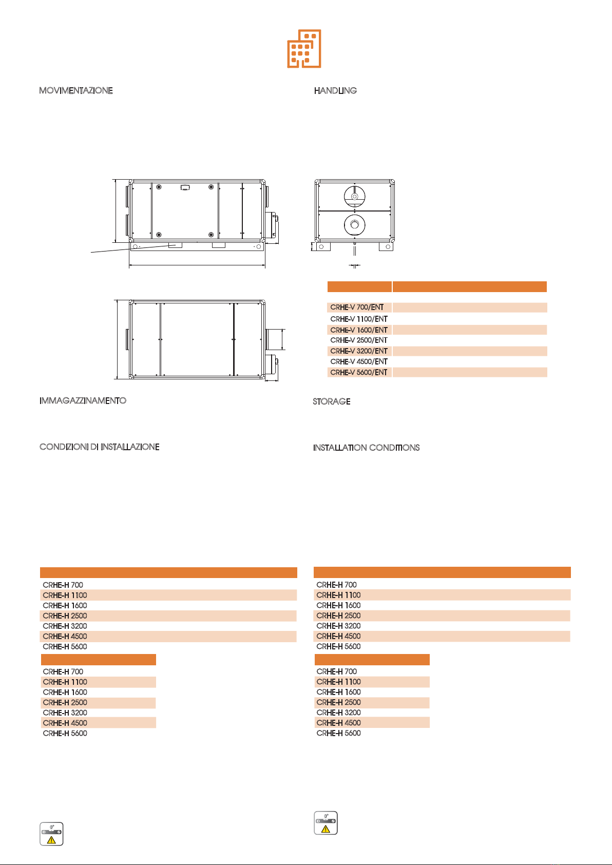
IMMAGAZZINAMENTO
Conservare l’unità in un luogo riparato, senza eccessiva umidità e
non soggetto a forti sbalzi termici al fine di evitare la formazione di
condensa all’interno dell’unità.
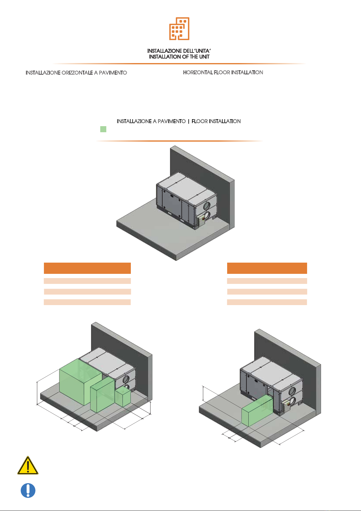
CONDIZIONI DI INSTALLAZIONE
Installazione all’interno o all'esterno di edifici con temperatura
ambiente compresa tra -15° e +50°C. Da evitare:
- aree in prossimità di fonti di calore, vapore, gas o liquidi infiam-
mabili e/o esplosivi, aree particolarmente polverose, vicinanza di
sorgenti d’acqua come vasche, docce o piscine.
- non toccare l’apparecchio con mani o piedi bagnati o umidi.
Da fare:
- utilizzare l’apparecchio solo per l’uso per il quale è stato espres-
samente costruito. Il costruttore non può essere considerato
responsabile per eventuali danni derivanti da usi impropri o errati.
- considerare un’area dove la mandata d’aria ed il rumore
dell’unità non rechino disturbo ai vicini;
- considerare una posizione che rispetti gli spazi minimi (come
indicato nel presente manuale);
- considerare una posizione che non ostruisca passaggi o ingressi;
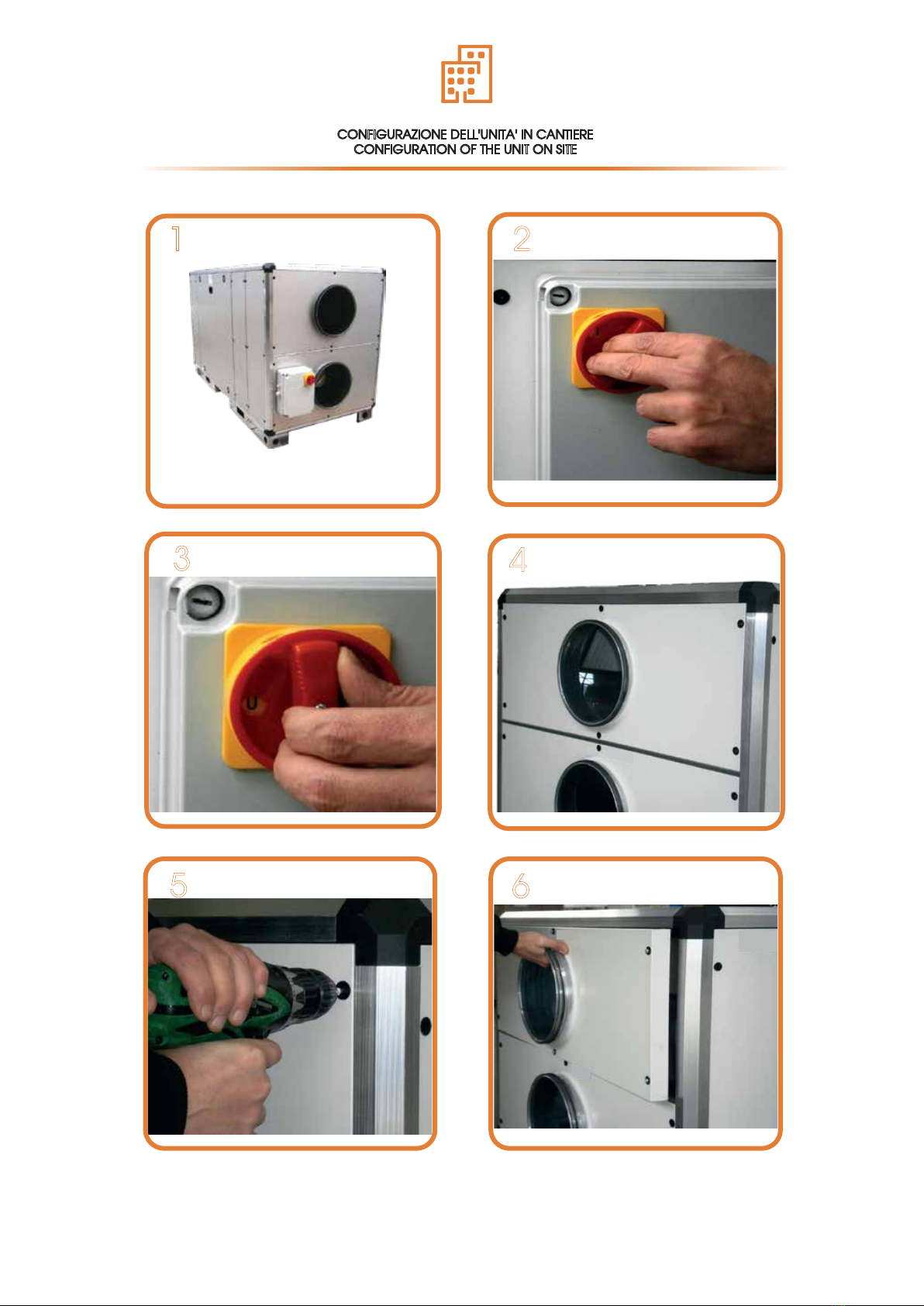
- Il grado di protezione dell’unità è IP20.
In caso di installazione all’esterno:
- collocare l’unità in luogo riparato da agenti atmosferici oppure
utilizzare l'apposito tettuccio parapioggia (se necessario congiun-
tamente alle apposite cuffie di prot zione con rete). In questo
caso il grado di protezione diventa IP22.
- Verificare che l’unità sia a livello
STORAGE
Store the unit in a sheltered place, without excessive moisture and
not subject to sudden changes of temperature in order to prevent
condensation inside the unit.
INSTALLATION CONDITIONS
Installation allowed inside the buildings or outdoor, with tempera-
ture between -15° to +50° C To avoid:
- areas near sources of heat source, steam or liquid flammable
and/or explosives gases, dusty areas, proximity to water sources
such as baths, showers or swimming pools
- Do not touch the device with wet or damp hands or feet.
To consider:
- use the device only for the use for which it was built. The manu-
facturer can not be held responsible for any damage caused by
improper or incorrect use.
- consider an area where the air flow and noise of the unit don’t
disturb the neighbors;
- minimum space required for the maintenance (as defined below);
- a position that does not block passageways or entrances;
- The protection degree is IP20.
In case of outdoor installation:
- place the unit in a place sheltered from the weather otherwise,
use the weather protective roof (if required, use the weather
protection cowl too). The protection degree changes in IP22
- Check that the unit is level
4
RUMORE DALLA CASSA (dB) RUMORE NEL CANALE (dB)
UNITÀ
52,2
51,4
58,6
59,8
63,2
68,4
73,3
55,9
56,2
64,7
64,8
68,4
73,4
77,9
CRHE-H 700
CRHE-H 1100
CRHE-H 1600
CRHE-H 2500
CRHE-H 3200
CRHE-H 4500
CRHE-H 5600
POTENZA (W)
UNITÀ
MOVIMENTAZIONE
Prima di spostare il prodotto, accertarsi che il mezzo utilizzato sia di
portata adeguata (vedi tabella pesi lordi nel capitolo “RICEVI-
MENTO DELLA MERCE”). Per il sollevamento servirsi di sollevatore a
forche, sollevando il pallet. Il sollevamento a mano massimo è
specificato nella norma 89/391/CEE e successive. Il pallet è
inforcabile sul lato lungo
HANDLING
Goods must be displaced by the correct equipment witha
suitable carrying capacity (see gross weight table in the chapter
"RECEIPT OF GOODS"). For pallet lifting use forklifts. According to
the standard 89/391/CEE and following standards. The pallet is
centrally forkable on all 4 sides;
A
UNITÀ|UNIT Dimensioni|Dimensions [mm]
CRHE-V 700
/ENT
1475 760 660 200
CRHE-V 1100
/ENT
CRHE-V 1600
/ENT
1645 960 760 250
104
140
Peso|Weight[kg]
C
A
Ø
1
/
2
"
g
a
s
Ø
B
100
160
160
CRHE-V 2500
/ENT
2150 1060 1180 355
CRHE-V 3200
/ENT
2305 1460 1180 450
268
352
CRHE-V 4500
/ENT
2465 1360 1320 500
CRHE-V 5600
/ENT
2545 1910 1320 560
406
674
2000 970 980 355 222
2 x 145
2 x 170
2 x 448
2 x 448
2 x 715
2 x 1270
2 x 1400
CRHE-H 700
CRHE-H 1100
CRHE-H 1600
CRHE-H 2500
CRHE-H 3200
CRHE-H 4500
CRHE-H 5600
NOISE FROM THE CASE (dB) NOISE IN TO THE DUCT (dB)
UNIT
52,2
51,4
58,6
59,8
63,2
68,4
73,3
55,9
56,2
64,7
64,8
68,4
73,4
77,9
CRHE-H 700
CRHE-H 1100
CRHE-H 1600
CRHE-H 2500
CRHE-H 3200
CRHE-H 4500
CRHE-H 5600
POWER (W)
UNIT
2 x 145
2 x 170
2 x 448
2 x 448
2 x 715
2 x 1270
2 x 1400
CRHE-H 700
CRHE-H 1100
CRHE-H 1600
CRHE-H 2500
CRHE-H 3200
CRHE-H 4500
CRHE-H 5600
spazio forche muletto
forklift space