manuals.online logo
Brands
  1. Home
  2. •
  3. Brands
  4. •
  5. UTEK
  6. •
  7. Media Converter
  8. •
  9. UTEK UT-2204 User manual

UTEK UT-2204 User manual

11 22 33
UT-2204 4-port RS-485 Smart Data Converter
Instruction Manual
Overview
UT-2204 is a RS-485 bus split hub designed for RS-485 system
used in dema nding envir onments. It supports a data communication
rate up to 115.2KBPS and has data buffers and microprocessors. It
uses external switching power supply for safety and reliability and is
ideal for engineering applications.
The built-in discrimination circuit can automatically sense the
direction of data flow and switch the enable control circuit to ensure
the switch of transmit and receive in RS-485 mod e. The communication
distance of RS-485 can exceed 1200m for stable performance, so it's
widely used in applications such as video supervision system as a
high-performance data interface converter.
UT-2204 RS-485 HUB provides star-type RS-485 bus connection.
Users can im prove the RS -485 bus structure and split bus segments
conveniently to improve the communication reliability. This feature
significantly improves the reliability of existing RS-485 network and
reduces maintenance interval. Reasonable use of UT-2204 RS-485HUB
can help to design a unique, highly reliable RS-485 system.
1.
2.
Features
Interface: Compatible with RS-232 and RS-485 standards of EIA/TIA
Electric connection: DB9/F socket for RS-232C interface, wiring
terminal for RS-485 end
3.
4.
5.
6.
7.
8.
9.
10. 210mm 140mm 32mm
11.
Transmission media: twisted-pair cable or shielded cable
Operation mode: Asynchronous half-duplex
Signal indicator: 9 signal LEDs: power (PWR), transmit(TXD1),
(TXD2), receive (RXD1),(RXD2) and error (E1-E4)
Data rate: 1200BPS-115.2KBPS
Protection class: 15KVESD protection;1500W lightning surge
protection for RS-485 interface
Transfer distance: 0-1.2 Kilometers (115200-1200BPS)
Power supply: DC9-30V 1A
Dimension
Working environment: -40 to 85 ,relative humidity of
5% to 95%
Panel and signal indication
There are 9 indicator lights on the front panel of UT-2204.
Wiring terminal and socket are on the rear panel. RS-232 Setup
port is used for baud rate setting (please refer to the software
instruction manual), SIGNAL OUT is alarm relay output, DC9-30
is the power input socket and wiring terminal, RS-485INPUT and
RS-485OUTPUT are data communication ports.
Figure 2 Rearpanel view ofUT-2204
Figure 1 Frontpanel view of UT-2204
Explanations of indicatorlights on the front panel ofUT-2204
power indicator,normally red
data transmitting indicator, normally flashinggreen,
indicating that thedata is transmitted from RS-485 Output
1-4 to RS-485Input 1-2ports
data receiving indicator, normally flashingyellow, indicating
that the datais transmittedfrom RS-485Input1-2 to RS-485 Output
1-4 ports
error alarm indicatorfor port1-port4; If it always turns
ON then theRS-485 interface devices connected to port1-port4
are short-circuited orreverse connected, and E1 corresponds to
port 1, andE4 corresponds to port 4, andat the same time alarm
relay will operateand the normally open contacts will be closed.
Userscan determinethe failed portand the connectedfaulty device
according to thestate of these error alarm indicators.
PWR
TX
RX
E1-E4
Electric interface and its definition
Figure 3 RS-232interface
RS-232C interface definition RS-485 interface definition
2 RS-485 interface definition
Wiring terminals
D x +
D x -
GND
Note: X canbe 1, 2, 3 or 4
Description
485+
485-
GND
E2
RX1
TX1PWR
4-port RS-485 SmartData Converter
E1
E4
E3
Model:UT-2204
RX2
TX2
Protective earth SIN(RXD)
Transmit dataSOUT(TXD)
Receive data SIN(RXD)
Empty
Signal ground GND
Empty
Empty
Empty
Transmit data
DB9 Female
(PIN)
1
2
3
4
5
6
7
8
9
RS-232C Interface signals
1 RS-232C interface definition
51
96
RS-485+ RS-485- GND
D 2
D 1
D 1+
GND
GND
D 2+
D 4
D 3
D 3+
GND
GND
D 4+
D 2
SIGNAL OUT
NO NC COM
DC9-30V
+
RS-232 Setup
D 1
D 1+
GND
GND
D 2+
RS-485 OUTPUT RS-485 INPUT
51
96
Figure 4 RS-485interface
Alarm and protection of RS-485 faults
Error alarm and protection of RS-485 interface is effective for
connecting multiple RS-485 devices for improved reliability. UT-2204
provides 4 subordinate ports used to determine quickly the faulty ports
and the connected faulty devices according to fault indicators. If fault
occurs then relay will a ct and normally open contacts will be connected
to the common point, so users can connect alarm bell or alarm light to
the relay output terminal.
Power supply and lightning protection
UT-2204 is powered by an external compact switching power supply
of 12V/1A. Other non-regulated voltage supply must not be used. This
may cause product damaged. Each RS-485 port of the UT-2204 has a
lightning protection of 1500W, and it can effectively prevent lightning
and ESD. Port 4 of UT-2204 is the protective earth of surge protection
and it's must be grounded correctly to avoid being not-used to ensure
safe communication.
Application note
The data on Input 1 and Input 2 will be transmitted immediately to
Output por t 1- port 4, and the data on any one port of Output port 1- port 4
will be stored to the data buffer and then forwarded to Input port 1- port 2,
so the time interval of Output port 1- port 4 should not be too short. For
example, if the data input of port 1- port 4 last for 100ms for each channel,
then each channel of port 1- port 4 should input data once for more than
400ms and the input data length should be less than 100 bytes, or data
may be lost.
4 5
Typical UT-2204 4-port RS-485HUB applications
1. 4 RS-485 devices controlling 1-2 devices, inwhich the 4 devices
on the RS-485 bus can simultaneously control 1-2 devices
RS-485 ADevice
( UT-2204)
OUTPUT1
OUTPUT2
OUTPUT3
OUTPUT4
3 Relay alarm signal output
SIGNAL OUT
No
Nc
COM
signal output
normally open
normally close
common
NO NC COM
2 Extension of 1-2 RS485 ports of amaster to 4 RS-485 ports
RS-485
Master Device 1 ( UT-2204)
Port1
Port2
Port3
Port4
RS-485
INPUT1
INPUT2
OUTUT1
OUTPUT2
OUTPUT3
OUTPUT4
Controlled Device 1
Port1
Port2
Port3
Port4
RS-485
INPUT1
RS-485
INPUT2
RS-485 BDevice
RS-485 DDevice Controlled Device 2
RS-485 ADevice
RS-485 BDevice
RS-485 CDevice
RS-485 DDevice
Master Device 2

Other UTEK Media Converter manuals

UTEK UT-6502 Series User manual

UTEK

UTEK UT-6502 Series User manual

UTEK UT-8812 User manual

UTEK

UTEK UT-8812 User manual

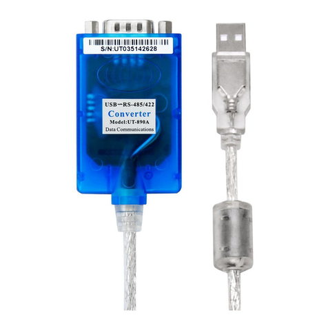
UTEK UT-890A User manual

UTEK

UTEK UT-890A User manual

UTEK UT-860 User manual

UTEK

UTEK UT-860 User manual

UTEK UT-2574 User manual

UTEK

UTEK UT-2574 User manual

Popular Media Converter manuals by other brands

TR-Electronic CMS582M-4096/4096 IOL DMS 14H7 KRF Assembly instructions

TR-Electronic

TR-Electronic CMS582M-4096/4096 IOL DMS 14H7 KRF Assembly instructions

Korenix JetCon 2301S user manual

Korenix

Korenix JetCon 2301S user manual

StarTech.com ET91000LCOAM manual

StarTech.com

StarTech.com ET91000LCOAM manual

Alesis AI-3 Reference manual

Alesis

Alesis AI-3 Reference manual

Caton Vpro 5100 user guide

Caton

Caton Vpro 5100 user guide

Cypress CSC-5500 Operation manual

Cypress

Cypress CSC-5500 Operation manual

H&B TX-100 Installation and instruction manual

H&B

H&B TX-100 Installation and instruction manual

Bolin Technology D Series user manual

Bolin Technology

Bolin Technology D Series user manual

IFM Electronic Efector 400 RN30 Series Device manual

IFM Electronic

IFM Electronic Efector 400 RN30 Series Device manual

GRASS VALLEY KUDOSPRO ULC2000 user manual

GRASS VALLEY

GRASS VALLEY KUDOSPRO ULC2000 user manual

Linear Technology DC1523A Demo Manual

Linear Technology

Linear Technology DC1523A Demo Manual

Lika ROTAPULS I28 Series quick start guide

Lika

Lika ROTAPULS I28 Series quick start guide

Weidmuller IE-MC-VL Series Hardware installation guide

Weidmuller

Weidmuller IE-MC-VL Series Hardware installation guide

Optical Systems Design OSD2139 Series Operator's manual

Optical Systems Design

Optical Systems Design OSD2139 Series Operator's manual

Tema Telecomunicazioni AD615/S product manual

Tema Telecomunicazioni

Tema Telecomunicazioni AD615/S product manual

KTI Networks KGC-352 Series installation guide

KTI Networks

KTI Networks KGC-352 Series installation guide

Gira 0588 Series operating instructions

Gira

Gira 0588 Series operating instructions

Lika SFA-5000-FD user guide

Lika

Lika SFA-5000-FD user guide

manuals.online logo
manuals.online logoBrands
  • About & Mission
  • Contact us
  • Privacy Policy
  • Terms and Conditions

Copyright 2025 Manuals.Online. All Rights Reserved.