Utilitech UT-81 User manual

ITEM/ARTÍCULO #0077888
DOORBELL
LLAMADOR
MODEL/MODELO #UT-81
Questions?/¿Preguntas?
Call technical service (English speaking only)
at 1-800-858-8501, 8:00 a.m. - 5:00 p.m., CST,
Monday - Friday.
Llame al servicio técnico (en inglés solamente) al
1-800-858-8501, de lunes a viernes de 8:00 a.m.
a 5:00 p.m., hora central estándar.
PACKAGE CONTENTS/CONTENIDO DEL PAQUETE
HARDWARE CONTENTS/ADITAMENTOS
Note: Hardware shown actual size/Nota: Los aditamentos se muestran en tamaño real.
202110-01A
A
AA BB CC
B
Screw
Tornillo
Wall Anchor
Ancla de expansión de pared
Diode
Diodo
x 1
Chime Cover
Cubierta para campanilla
x 1
Chime Base
Base de la campanilla
x 2x 4 x 4
*Illustrations may vary from actual unit.
*Las ilustraciones pueden variar de la unidad real.
ATTACH YOUR RECEIPT HERE
ADJUNTE SU RECIBO AQUÍ
Purchase Date/Fecha de compra

PREPARATION/PREPARACIÓN
Before beginning installation of product, make sure all parts are present. Compare parts with package contents list and hardware contents list. If any part is
missing or damaged, do not attempt to assemble, install, or operate the product.
Estimated Installation Time: 30 minutes
Tools Required for Assembly (not included): Phillips and athead screwdrivers, drill, 7/32 in. drill bit, and safety glasses
Antes de comenzar a instalar el producto, asegúrese de tener todas las piezas. Compare las piezas con la lista del contenido del paquete y la lista de
aditamentos. No intente ensamblar, instalar ni operar el producto si faltara alguna pieza o si éstas estuvieran dañadas.
Tiempo de instalación estimado: 30 minutos
Herramientas necesarias para el ensamblaje (no se incluyen): Destornilladores de cabeza plana y Phillips, taladro, broca para taladro de 1/16", gafas de
seguridad
INSTALLATION INSTRUCTIONS/INSTRUCCIONES DE INSTALACIÓN
1. Verify the existing transformer power
rating is 10 or 15 watts and 16 volts AC.
Verique que la clasicación de potencia
del transformador sea de 10 o 15 vatios,
16 voltios de CA.
2. Remove cover from existing chime and
label all wires before disconnecting:
“F” – Front door push button wire
“T” – Transformer wire
“R” – Rear door push button wire
Retire la cubierta de la campanilla
existente y etiquete todos los cables
antes de desconectar:
“F” – Cable del botón pulsador de la
puerta delantera
“T” – Cable del transformador
“R” – Cable del botón pulsador de la
puerta posterior
3. Disconnect all wires from existing chime
and remove chime from mounting
surface.
Desconecte todos los cables de
la campanilla existente y retire la
campanilla de la supercie de montaje.
4. Using the UP indicator on the chime
base (B), place the chime base (B)
horizontally on the mounting surface
and verify it is level. Mark the mounting
surface through the four mounting holes.
Con el indicador “UP” (ARRIBA)
ubicado en la base de la campanilla
(B), coloque la base de la campanilla en
sentido horizontal (B) en la supercie de
montaje y verique que esté nivelada.
Marque la supercie de montaje en los
cuatro oricios de montaje.
5.
Drill four 7/32 in. pilot holes and insert
wall anchors (BB).
SAFETY INFORMATION/INFORMACIÓN DE SEGURIDAD
Please read and understand this entire manual before attempting to assemble, operate, or install the product.
Lea y comprenda completamente este manual antes de intentar ensamblar, usar o instalar el producto.
Electrical work must be in accordance with national and local electrical codes. If in doubt, consult a qualied electrician.
El trabajo eléctrico debe cumplir con los códigos eléctricos nacionales y locales. Si tiene dudas, consulte con un electricista calicado.
IMPORTANT: Proper installation requires a diode on the front door push button.
IMPORTANTE: La instalación correcta requiere un diodo en el botón pulsador de la puerta delantera.
Taladre cuatro oricios guía de 5,5 mm e
inserte las anclas de expansión de pared
(BB).
6. Route the wires through the wire entrance
hole in the chime base (B) and attach the
chime base (B) to the mounting surface
using the screws (AA).
Guíe los cables a través el oricio de
entrada del cable en la base de la
campanilla (B) y coloque la base de
la campanilla (B) en la supercie de
montaje usando los tornillos (AA).
7. Connect the chime wires to the chime
base (B). Wire
“F” to screw terminal
labeled “FRONT”. Wire “T” to screw
terminal labeled “TRANS”. Wire “R” to
screw terminal labeled “REAR”.
Conecte los cables de la campanilla en
la base de la campanilla (B). Conecte
el cable “F” al terminal del tornillo
etiquetado “FRONT” (DELANTERA).
Conecte el cable “T” al terminal del
tornillo etiquetado “TRANS” Conecte
el cable “R” al terminal del tornillo
etiquetado “REAR” (POSTERIOR).
8. Press the chime cover (A) onto the chime
base (B). Note: To remove chime cover
(A), rmly grasp cover (A) and pull.
Presione la cubierta de la campanilla (A)
hacia la base de la campanilla (B). Nota:
Para sacar la cubierta de la campanilla
(A) agarre rmemente la cubierta de la
campanilla (A) y tire.
9.
The chime will not play the entire eight-
note tune if a diode (CC) is not installed
on the main push button (not included).
If diode (CC) is needed, loosen the two
wiring screws on the back of the existing
push button and wrap each of the ends of
the diode (CC) around each screw. Tighten
screws onto diode (CC) and wiring.
2
FRONT
REAR
TRANS
R
T
F
3
R
T
F
5
BB
6
R
T
F
AA
B
4B
7
R
T
F
B
8B
A
9
CC
1
INSTALLATION INSTRUCTIONS/INSTRUCCIONES DE INSTALACIÓN
TROUBLESHOOTING/SOLUCIÓN DE PROBLEMAS
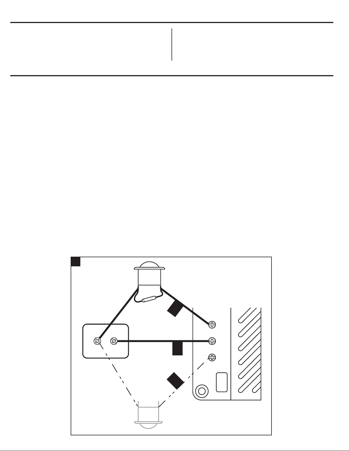
1. PROBLEM/PROBLEMA: Chime does not sound./No suena la campanilla.
A. POSSIBLE CAUSE/CAUSA POSIBLE: Chime may not be working properly./La campanilla puede no estar funcionando correctamente.
A. CORRECTIVE ACTION/ACCIÓN CORRECTIVA: Disconnect wire from terminal marked “TRANS” (Figure 1). While someone presses the push button
at front door, quickly touch the “TRANS” wire to terminal marked “FRONT”. You will see a small spark if push button, wiring, and transformer are
operating properly. Repeat the steps for “REAR” terminal and rear push button. If wiring between transformer and push button(s) checks out properly,
replace chime./Desconecte el cable del terminal marcado “TRANS” (Figura 1). Mientras alguien presiona el botón pulsador en la puerta delantera,
toque rápidamente el cable “TRANS” con el terminal marcado “FRONT” (DELANTERA). Verá una pequeña chispa si el botón pulsador, el cableado y el
transformador están funcionando correctamente. Repita los pasos para el terminal “REAR” (POSTERIOR) y el botón pulsador posterior. Si el cableado
entre el transformador y los botones pulsadores es correcto, reemplace la campanilla.
B. POSSIBLE CAUSE/CAUSA POSIBLE: Transformer may not be working properly./El transformador puede no estar funcionando correctamente.
B. CORRECTIVE ACTION/ACCIÓN CORRECTIVA: Test transformer voltage output with a volt meter (Figure 1). If a volt meter is not available, quickly
touch both low-voltage terminals on the transformer at the same time with a screwdriver. You will see a small spark if transformer is operating properly.
If no spark is seen, replace transformer./Pruebe la salida de voltaje del transformador con un voltímetro (Figura 1). Si no hay disponible un voltímetro,
toque rápidamente ambos terminales de voltaje bajo del transformador al mismo tiempo con un destornillador. Verá una pequeña chispa si el
transformador está funcionando correctamente. Si no se ve una chispa, reemplace el transformador.
C. POSSIBLE CAUSE/CAUSA POSIBLE: Push button may not be working properly./El botón pulsador puede no estar funcionando correctamente.
C. CORRECTIVE ACTION/ACCIÓN CORRECTIVA: Remove push button that is not working from the door frame. Disconnect wires from terminals and
touch bare wires together (Figure 1). If chime sounds, push button is defective. Replace push button./Retire el botón pulsador que no está funcionando
desde el marco de la puerta. Desconecte los cables de los terminales y toque los cables desnudos juntos (Figura 1). Si suena la campanilla, el botón
pulsador está defectuoso. Reemplace el botón pulsador.
2. PROBLEM/PROBLEMA: Chime sounds but does not play entire Westminster tune./La campanilla suena pero no reproduce toda la melodía Westminster.
POSSIBLE CAUSE/CAUSA POSIBLE: Push button diode is not installed correctly or is not working properly./El diodo del botón pulsador no está bien
instalado o no funciona correctamente.
CORRECTIVE ACTION/ACCIÓN CORRECTIVA: Verify diode is attached securely to push button. Chime may not function properly if a diode is installed
on more than one push button. Note: Some push buttons have a pre-installed diode. An additional diode should not be installed if the push button has a
pre-installed diode. If eight-note tune still does not sound completely, replace diode (Type 1N4001-50V-1A, available at local electrical component supplier)./
Verique que el diodo esté colocado de forma segura en el botón pulsador. La campanilla puede no funcionar correctamente si un diodo está instalado
en más de un botón pulsador. Nota: Algunos botones pulsadores tienen diodos instalados previamente. No se debe instalar un diodo adicional si el
botón pulsador tiene un diodo instalado previamente. Si la melodía de ocho tonos todavía no suena completa, reemplace el diodo (Tipo 1N4001-50V-1A,
disponible en el proveedor del componente eléctrico local).
La campanilla no reproducirá toda la melodía de ocho tonos si no se
instala un diodo en el botón pulsador principal
(no se incluyen)
. Si se
necesita un diodo (CC), suelte los dos tornillos del cableado en la parte
posterior del botón pulsador existente y enrolle ambos extremos del
diodo (CC) alrededor de cada tornillo. Apriete los tornillos en el diodo
(CC) y el cableado.
FRONT TRANS REAR
R
T
F
Chime
Campanilla
Front Door Push Button
With Diode
Botón pulsador de la
puerta delantera con diodo
1
Transformer
Transformador
Rear Door Push Button (If
Applicable)
Botón pulsador de la puerta
posterior (si corresponde)

WARRANTY/GARANTÍA
This is a “Limited Warranty” which gives you specic legal rights. You may also have other rights which vary from state to state or province to province.
For a period of one year from the date of purchase, any malfunction caused by factory defective parts or workmanship will be corrected at no charge to you.
Repair service, adjustment and calibration due to misuse, abuse or negligence, light bulbs, batteries, and other expendable items are not covered by this
warranty. Unauthorized service or modication of the product or of any furnished component will void this warranty in its entirety. This warranty does not include
reimbursement for inconvenience, installation, setup time, loss of use, unauthorized service, or return shipping charges.
This warranty covers only the manufacturer’s assembled products and is not extended to other equipment and components that a customer uses in conjunction
with our products.
THIS WARRANTY IS IN LIEU OF ALL OTHER WARRANTIES, EXPRESSED OR IMPLIED, INCLUDING ANY WARRANTY, REPRESENTATION OR
CONDITION OF MERCHANT ABILITY OR THAT THE PRODUCTS ARE FIT FOR ANY PARTICULAR PURPOSE OR USE, AND SPECIFICALLY IN LIEU OF
ALL SPECIAL, INDIRECT, INCIDENTAL, OR CONSEQUENTIAL DAMAGES.
REPAIR OR REPLACEMENT SHALL BE THE SOLE REMEDY OF THE CUSTOMER AND THERE SHALL BE NO LIABILITY ON THE PART OF THE
MANUFACTURER FOR ANY SPECIAL, INDIRECT, INCIDENTAL, OR CONSEQUENTIAL DAMAGES, INCLUDING BUT NOT LIMITED TO ANY LOSS
OF BUSINESS OR PROFITS, WHETHER OR NOT FORESEEABLE. Some states or provinces do not allow the exclusion or limitation of incidental or
consequential damages, so the above limitation or exclusion may not apply to you. Please keep your dated sales receipt; it is required for all warranty requests.
Esta es una “Garantía limitada" que le da derechos legales especícos. Usted también puede tener otros derechos que varían según el estado o la provincia.
Por un período de un año desde la fecha de compra, cualquier falla causada por piezas con defectos de fábrica o con defecto en la mano de obra se corregirá
sin cargo.
Esta garantía no cubre servicios de reparación, regulación y calibración debido al mal uso, abuso o negligencia, ni las bombillas de luz, las baterías y otros
artículos fungibles. La reparación no autorizada o la modicación del producto o de cualquiera de los componentes suministrados anularán esta garantía en su
totalidad. Esta garantía no incluye reembolsos por inconvenientes, instalación, tiempo de ensamblaje, pérdida de uso, reparación no autorizada o cargos de
envío por devolución.
Esta garantía cubre solamente los productos ensamblados del fabricante y no se extiende a otros equipos y componentes que un cliente usa junto con
nuestros productos.
ESTA GARANTÍA REEMPLAZA TODAS LAS DEMÁS GARANTÍAS, EXPRESAS O IMPLÍCITAS, INCLUIDA CUALQUIER GARANTÍA, REPRESENTACIÓN
O CONDICIÓN DE COMERCIABILIDAD O ADAPTACIÓN DE LOS PRODUCTOS PARA CUALQUIER PROPÓSITO O USO PARTICULAR Y
ESPECÍFICAMENTE REPRESENTA TODOS LOS DAÑOS ESPECIALES, INDIRECTOS, INCIDENTALES O RESULTANTES.
LAS REPARACIONES O REEMPLAZOS SERÁN LOS ÚNICOS RESARCIMIENTOS PARA EL CLIENTE Y NO HABRÁ RESPONSABILIDAD ALGUNA DE
PARTE DEL FABRICANTE POR NINGÚN DAÑO ESPECIAL, INDIRECTO, ACCIDENTAL O RESULTANTE INCLUIDOS, ENTRE OTROS, LA PÉRDIDA
DE ACTIVIDAD O LUCRO CESANTE, FUEREN O NO PREVISIBLES. Algunos estados o provincias no permiten la exclusión o limitación de los daños
accidentales o resultantes, por lo tanto puede que la limitación o la exclusión anterior no se aplique en su caso. Guarde su recibo de compras con fecha, se
requiere para todos los pedidos de la garantía.
Printed in China/Impreso en China
This manual suits for next models
1
Other Utilitech Accessories manuals

Utilitech
Utilitech UT-7343 User manual

Utilitech
Utilitech UT-75 User manual

Utilitech
Utilitech UT-2735 User manual

Utilitech
Utilitech 0568972 User manual

Utilitech
Utilitech UT-32 User manual

Utilitech
Utilitech UT-7353 User manual

Utilitech
Utilitech R1615D36 User manual

Utilitech
Utilitech UT-103 User manual

Utilitech
Utilitech UT-7451 User manual


