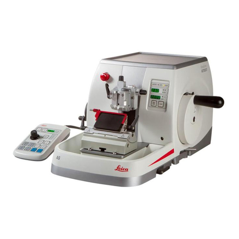
Leica RM2125RTS User manual

Leica RM2125 RTS
Rotary Microtome
Instructions for Use
English
Order No.: 14 0457 80101 - Revision J
Always keep these Instructions for Use with the instrument.
Read carefully before working with the instrument.
Version 2.6, Revision J - 11.2019


3
Leica RM2125 RTS
The information, numerical data, notes and value judgments contained in this manual represent the
current state of scientific knowledge and state-of-the-art technology as we understand it following
thorough investigation in this field.
We are under no obligation to update the present manual periodically and on an ongoing basis
according to the latest technical developments, nor to provide our customers with additional copies,
updates etc. of this manual.
To the extent permitted in accordance with the national legal system as applicable in each individual
case, we shall not be held liable for erroneous statements, drawings, technical illustrations etc.
contained in this manual.
In particular, no liability whatsoever is accepted for any financial loss or consequential damage caused
by or related to compliance with statements or other information in this manual.
Statements, drawings, illustrations and other information regarding the contents or technical details of
the present Instructions for Use are not to be considered warranted characteristics of our products.
These are determined only by the contract provisions agreed between ourselves and our customers.
Leica reserves the right to change technical specifications as well as manufacturing processes without
prior notice. Only in this way is it possible to continuously improve the technology and manufacturing
techniques used in our products.
This document is protected under copyright laws. All copyrights to this documentation are held by Leica
Biosystems Nussloch GmbH.
Any reproduction of text and illustrations (or of any parts thereof) by means of print, photocopy,
microfiche, web cam or other methods – including any electronic systems and media – requires express
prior permission in writing by Leica Biosystems Nussloch GmbH.
For the instrument serial number and year of manufacture, please refer to the nameplate on the
instrument.
© Leica Biosystems Nussloch GmbH
Note
Leica Biosystems Nussloch GmbH
Heidelberger Str. 17 - 19
D-69226 Nussloch
Germany
Tel.: +49 - (0) 6224 - 143 0
Fax: +49 - (0) 6224 - 143 268
Web: www.LeicaBiosystems.com
Assembly contracted to Leica Microsystems Ltd. Shanghai

4Version 2.6, Revision J
Table of Contents
1. Important Information ................................................................................................................................ 6
1.1 Symbols in the text and their meanings....................................................................................................... 6
1.2 Qualification of personnel.............................................................................................................................. 8
1.3 Intended use of instrument............................................................................................................................ 8
1.4 Instrument type................................................................................................................................................ 8
2. Safety ............................................................................................................................................................ 9
2.1 Safety Notes..................................................................................................................................................... 9
2.2 Warnings........................................................................................................................................................... 9
2.3 Integrated safety devices............................................................................................................................. 11
3. Instrument components and specifications ........................................................................................ 14
3.1 Overview — instrument components ........................................................................................................ 14
3.2 Instrument specifications............................................................................................................................. 15
3.3 Technical Data............................................................................................................................................... 16
4. Instrument Setup....................................................................................................................................... 18
4.1 Installation site requirements...................................................................................................................... 18
4.2 Standard delivery........................................................................................................................................... 18
4.3 Unpacking and installation........................................................................................................................... 19
4.4 Inserting the specimen clamp..................................................................................................................... 21
4.5 Direct mounting of the specimen clamp on the specimen holder fixture............................................ 22
4.6 Attaching the knife holder base, non-orientable ..................................................................................... 23
4.7 Inserting the knife holder, non-orientable................................................................................................. 24
5. Operation.................................................................................................................................................... 25
5.1 Clamping the specimen ................................................................................................................................ 25
5.2 Clamping the knife / disposable blade ....................................................................................................... 25
5.3 Adjusting the clearance angle .................................................................................................................... 26
5.4 Specimen retraction (specimen orientation)............................................................................................ 27
5.5 Orienting the specimen (only a directional specimen holder fixture) .................................................. 28
5.6 Cutting (trimming) the specimen................................................................................................................. 29
5.7 Sectioning....................................................................................................................................................... 32
5.8 Changing specimens..................................................................................................................................... 33
5.9 Accessories.................................................................................................................................................... 33
5.9.1 Standard specimen clamp (optional) ......................................................................................................... 33
5.9.2 Vee insert (optional)...................................................................................................................................... 34
5.9.3 Foil clamp Type 1 (optional) ......................................................................................................................... 34
5.9.4 Universal cassette clamp (optional)........................................................................................................... 36
5.9.5 Round specimen holder (optional).............................................................................................................. 37
5.9.6 Knife holder base........................................................................................................................................... 38
5.9.7 Knife holder N/NZ.......................................................................................................................................... 39
5.9.8 Knife holder E/E-TC........................................................................................................................................ 41
5.9.9 Knife holder E ................................................................................................................................................. 42
5.9.10 Overview – accessories............................................................................................................................... 47

5
Leica RM2125 RTS
Table of Contents
6. Cleaning and Maintenance..................................................................................................................... 49
6.1 Cleaning the instrument................................................................................................................................ 49
6.2 Maintenance instructions............................................................................................................................ 52
7. Optional Accessories............................................................................................................................... 54
8. Troubleshooting ........................................................................................................................................ 62
8.1 Possible faults................................................................................................................................................ 62
8.2 Instrument malfunctions............................................................................................................................... 63
9. Warranty and Service .............................................................................................................................. 64
10. Decontamination Confirmation.............................................................................................................. 65

6Version 2.6, Revision J
Important Information
1
1. Important Information
1.1 Symbols in the text and their meanings
Symbol: Title of the symbol: Warning
Description: Warnings appear in a white box and are marked by a
warning triangle.
Symbol: Title of the symbol: Note
Description: Notes, i. e. important user information, appear in a
white box and are marked by an information symbol.
Symbol: Title of the symbol: Item number
→"Fig. 7 - 1"Description: Item numbers for numbering illustrations. Numbers in
red refer to item numbers in illustrations.
Symbol: Title of the symbol: Manufacturer
Description: Indicates the manufacturer of the medical product.
Symbol: Title of the symbol: Manufacturing date
Description: Indicates the date when the medical device was
manufactured.
Symbol: Title of the symbol: Consult Instructions for Use
Description: Indicates the need for the user to consult the
Instructions for Use.
Symbol: Title of the symbol: Article number
Description: Indicates the manufacturer's catalog number so that
the medical device can be identified.
Symbol: Title of the symbol: Serial number
Description: Indicates the manufacturer's serial number so that a
specific medical device can be identified.
Symbol: Title of the symbol: In vitro diagnostic medical device
Description: Indicates a medical device that is intended to be
used as an in vitro diagnostic medical device.
Symbol: Title of the symbol: CE Compliance
Description: The CE marking is the manufacturer's declaration
that the medical product meets the requirements of
the applicable EC directives.
Symbol: Title of the symbol: Fragile, handle with care
Description: Indicates a medical device that can be broken or
damaged if not handled carefully.

7
Leica RM2125 RTS
Important Information 1
Symbol: Title of the symbol: Store dry
Description: Indicates a medical device that needs to be
protected from moisture.
Symbol: Title of the symbol: This way up
Description: Indicates correct upright position of the transport
package.
Symbol: Title of the symbol: Stack limit
Description: The largest number of identical packages allowed to
be stacked; "3" stands for the number of permitted
packages.
Symbol: Title of the symbol: Temperature limit for transport
Description: Indicates the temperature limits for transport to
which the medical device can be safely exposed.
Symbol: Title of the symbol: Temperature limit for storage
Description: Indicates the temperature limits for storage to which
the medical device can be safely exposed.
Symbol: Title of the symbol: Humidity limitation for transport and storage
Description: Indicates the range of humidity for transport and
storage to which the medical device can be safely
exposed.

8Version 2.6, Revision J
Important Information
1
Symbol: Title of the symbol: Tilt indicator
Description Tip-n-Tell indicator to monitor whether the shipment
has been transported and stored in upright position
according to your requirements. With a pitch of
60° or more, the blue quartz sand flows into the
arrow-shaped indicator window and sticks there
permanently.
Improper handling of the shipment is immediately
detectable and can be proven definitively.
Symbol: Title of the symbol: Shockdot Impact Indicator
Description In the Shockwatch system, a shock dot shows
shocks or impacts that are above a specified
intensity through red coloration. Exceeding a defined
acceleration (g value) causes the indicator tube to
change color.
Symbol: Title of the symbol: Recycling
Description: Indicates, that the item can be recycled where
correct facilities exist.
1.2 Qualification of personnel
• The Leica RM2125 RTS may be operated by trained laboratory personnel only. The instrument is
intended for professional use only.
• All laboratory personnel designated to operate the Leica instrument must read these Instructions for
Use carefully and must be familiar with all technical features of the instrument before attempting to
operate it.
1.3 Intended use of instrument
The RM2125 RTS is a manually operated rotation microtome specifically designed for creating thin
sections of human tissue specimens of varying hardness for histological medical diagnosis, e.g. cancer
diagnosis. It is intended for sectioning soft and hard human specimens, as long as they are suitable for
being cut manually.
ANY OTHER USE OF THE INSTRUMENT IS CONSIDERED IMPROPER!
1.4 Instrument type
All information provided in these Instructions for Use applies only to the instrument type indicated on
the title page.
An identification label with the serial number is fastened to the left side of the instrument.

9
Leica RM2125 RTS
Safety 2
2. Safety
Warning
The safety and caution notes in this chapter must be observed at all times.
Be sure to read these notes even if you are already familiar with the operation and use of other Leica
products.
2.1 Safety Notes
These Instructions for Use include important information related to the operating safety and
maintenance of the instrument.
The instruction manual is an important part of the product, which must be read carefully prior to setup
and use and must always be kept near the instrument.
To maintain this condition and ensure safe operation, the user must observe all notes and warnings
contained in these Instructions for Use.
This instrument has been built and tested in accordance with the safety requirements for electrical
equipment for measurement, control, and laboratory use.
For current information about applicable standards, please refer to the CE Declaration of Conformity on
our Internet site:
www.LeicaBiosystems.com
Note
These Instructions for Use must be appropriately supplemented as required by the existing
regulations on accident prevention and environmental safety in the operator‘s country.
Warning
The protective devices located on the instrument and the accessories must not be removed or
modified. Only service personnel qualified by Leica may repair the instrument and access the
instrument's internal components.
2.2 Warnings
The safety devices installed in this instrument by the manufacturer only constitute the basis for accident
prevention. Operating the instrument safely is, above all, the responsibility of the owner, as well as the
designated personnel who operate, service or clean the instrument.
To ensure trouble-free operation of the instrument, make sure to comply with the following instructions
and warnings.

10 Version 2.6, Revision J
Safety
2
Warnings – Markings on the instrument itself
Warning
• Safety notes on the instrument itself, which are marked with a warning triangle, indicate that the
correct operating instructions (as defined in these Instructions for Use) must be followed when
operating or replacing the item marked.
• Failure to adhere to these instructions may result in an accident, personal injury, damage to the
instrument or accessory equipment.
Warnings – Transport and installation
Warning
• Extreme temperature fluctuations and high humidity levels may cause harmful condensation within
the instrument. Always ensure appropriate environmental conditions are met during storage and
operation. Refer to the Technical Data section for further details (→p. 16 – 3.3 Technical Data).
• After transporting the instrument, wait for at least two hours to allow the instrument to adopt the
ambient temperature before switching it on.
• Once unpacked, the instrument may be transported only in an upright position.
• Do not transport the instrument by holding it by the handwheel grips, coarse driving wheel or the
knob for setting the section thickness.
• The protective devices located on the instrument and the accessories must not be removed or
modified.
Warnings – Operating the instrument
Warning
• Take care when handling microtome knives and disposable blades. The cutting edge is extremely
• sharp and can cause serious injuries! It is strongly recommended that you wear cut-resistant
safety gloves (→p. 54 – 7. Optional Accessories).
• Always remove the knife / blade before detaching the knife holder from the instrument.
• Always put the knives back into the knife case when not in use!
• Never place a knife anywhere with the cutting edge facing upwards and never try to catch a falling
knife!
• Always clamp the specimen block BEFORE clamping the knife.
• Prior to manipulating the knife and specimen, or changing the specimen or knife, and during breaks,
always lock the handwheel and cover the cutting edge with the knife guard!
• Always wear safety goggles when sectioning brittle specimens! Specimens may splinter!
• Ensure that liquids do not enter the interior of the instrument during work!
• Immediately pick up and dispose of wax that has fallen on the floor. It poses a slipping hazard, and
therefore a risk of injury!
• When the specimen retraction is activated, the specimen MUST NOT be oriented or brought
closer to the knife in the retraction phase. The same applies to the "rocking mode". If a block is
oriented during retraction, the block will advance by the retraction value PLUS the selected section
thickness before the next section. This may cause damage to both specimen and knife!
• Prior to sectioning, check that the specimen is securely clamped in the specimen clamp – failure to
observe this poses the risk of damaging the specimen.

11
Leica RM2125 RTS
Safety 2
Warnings – Maintenance and Cleaning
Warning
• Only authorized and qualified service personnel may access the internal components of the
instrument for service and repair!
• Do NOT catch accessories that are falling down – there is a risk of injury!
• Lock the handwheel before cleaning!
• Do not use any solvents containing acetone or xylene for cleaning!
• Ensure that liquids do not enter the interior of the instrument during cleaning!
• When using cleaners, please comply with the safety instructions of the manufacturer and the
laboratory safety regulations!
2.3 Integrated safety devices
The instrument is equipped with the following safety devices:
Handwheel lock
1
2
Fig. 1
(→Fig. 1-1)Handwheel handle
(→Fig. 1-2)Lever in position = handwheel locked
(→Fig. 1-2)Lever in position = handwheel released
The handwheel can be locked in the 12 o'clock position (→Fig. 1-1).

12 Version 2.6, Revision J
Safety
2
As soon as the handwheel handle (→Fig. 1-1)is pushed in to the left, the handwheel engages the next
time it reaches the 12 o'clock position, which locks it mechanically.
Functional test:
• To activate the lock, press the handwheel handle (→Fig. 1-1)to the left. The handwheel is now
mechanically locked in the 12 o'clock position and can no longer be rotated.
• To deactivate the lock, pull out the handwheel handle (→Fig. 1-1)to the right.
Handwheel brake
Using the lever (→Fig. 1-2)on the right side of the microtome base plate, the handwheel brake can be
activated with the handwheel in any position. If the lever is pressed upwards, the handwheel cannot
be moved any more. The two lever positions are marked by corresponding dots on the microtome base
plate (→Fig. 1).
Knife guard on the knife holder
Each knife holder is equipped with a tightly mounted knife guard ((→Fig. 2-1), (→Fig. 3-1)). This makes
it possible to cover completely the cutting edge in every knife or blade position.
Warning
Lock the handwheel and cover the knife edge with the knife guard prior to any manipulation of knife
or specimen, as well as prior to changing specimens and during all work breaks!
Knife holder N
Fig. 2
1
2
2
The knife guard (→Fig. 2-1)of the knife holder N can be easily positioned via the two handles
(→Fig. 2-2).
To cover the knife edge, push both cover strips of the knife guard to the center.

14 Version 2.6, Revision J
Instrument components and specifications
3
3. Instrument components and specifications
3.1 Overview — instrument components
Leica RM2125 RTS (from the right)
1
6
2
7
3
8
4
5
9
Fig. 4
(→Fig. 4-1)Universal cassette clamp
(→Fig. 4-2)Knife holder E
(→Fig. 4-3)Knife holder base with lateral movement
(→Fig. 4-4)Clamping lever for Knife holder base
(→Fig. 4-5)Specimen holder fixture, directional
(→Fig. 4-6)Handwheel handle with locking function
(→Fig. 4-7)Handwheel
(→Fig. 4-8)Specimen retraction ON/OFF
(→Fig. 4-9)Lever for activating the Handwheel brake

15
Leica RM2125 RTS
Instrument components and specifications 3
Leica RM2125 RTS (from left)
1
5
26
3
4
7
Fig. 5
(→Fig. 5-1)Coarse feed wheel
(→Fig. 5-2)Select the running direction for the coarse feed wheel
(→Fig. 5-3)Lever for activating the mechanical trimming function
(→Fig. 5-4)Adjusting knob for setting the section thickness
(→Fig. 5-5)Window for displaying the section thickness
(→Fig. 5-6)Knife holder N
(→Fig. 5-7)Knife holder base, non-orientable
3.2 Instrument specifications
The Leica RM2125 RTS is a manually operated rotary microtome.
• The specimen feed system and stroke mechanism are equipped with slack-free and maintenance-
free cross roller bearings. They are housed in a polymer housing and protected against dust just like
the coarse feed system.
• The handwheel can be locked into place in the upper position via the handwheel handle. In addition,
it is possible to lock the handwheel in any position via the clamping lever on the baseplate.
• Sectioning is done manually by rotating the easy-to-move handwheel, which is accurately balanced
by means of a counterweight.
• The coarse feed is actuated via the coarse feed wheel on the left side of the instrument. The user
can select the coarse feed wheel direction of rotation depending on the requirements (clockwise or
counterclockwise).
• The section thickness is set via a rotary knob and can be read accurately in the viewing window.
Section thickness setting of 0.5 to 60 μm.
• The instrument has a slit cover that prevents section waste from ingressing into the interior of the
instrument.
• The instrument has a mechanical trimming function that is activated by a key lever. Steps are
possible at 10 μm and 50 μm.

16 Version 2.6, Revision J
Instrument components and specifications
3
• Another additional function is the specimen retraction, which protects the knife and specimen. The
user can switch the retraction function ON or OFF.
When retracted, the specimen is drawn back 20 μm into the upper end position after the sectioning
stroke during the return movement. Before the feed motion of the new section thickness, first it
advances by the retraction value.
3.3 Technical Data
Installation site requirements
Operating temperature range: 18 °C- 30 °C
Temperature range during storage: 5 °C - 50 °C
Relative humidity: max. 80 %, non-condensing
Storage humidity: min. 10 % r.H., max. 85 % r.H.
General
Section thickness range: 0.5 - 60 μm
Section thickness settings: from 0 - 2 μm in 0.5 μm increments
from 2 - 10 μm in 1 μm increments
from 10 - 20 μm in 2 μm increments
from 20 - 60 μm in 5 μm increments
Object feed: 25 mm
Vertical stroke: 59 mm
Max. sectioning area without retractions: 58 mm
Max. sectioning area with retractions: 52 mm
Specimen retraction: approx. 20 μm; can be turned off
Max. specimen size (WxHxD): 50 x50 x40 mm
Dimensions and weight
Width 438 mm
Depth 472 mm
Height 265 mm
Working height (knife blade) 105 mm
Weight (without accessories) 29 kg
Optional equipment and optional accessories
Specimen orientation (option)
Horizontal:
Vertical:
± 8°
± 8°
Angle of rotation: ± 90°

17
Leica RM2125 RTS
Instrument components and specifications 3
Trimming stages: 10 μm 50 μm
Repositioning of knife holder base
with lateral movement
North-south:
East-west movement:
without lateral movement
North-south:
± 24 mm
± 20 mm
± 25 mm

18 Version 2.6, Revision J
Instrument Setup
4
4. Instrument Setup
4.1 Installation site requirements
• The instrument requires an installation area of approx. 438 x 472 mm.
• Room temperature consistently between +10 °C and +35 °C
• Relative humidity 80 % maximum - non-condensing
• Ambient pressure from 740 hPa to 1100 hPa
• Elevation: up to max. 2000 m NN
• The instrument is designed for indoor use only.
• Obstruction-free access to the handwheel.
• For smooth function, also make sure that no other instruments that cause vibrations are standing in
the immediate vicinity of the instrument.
• The substrate must be largely vibration-free and have sufficient load capacity and rigidity for the
weight of the instrument.
• Avoid vibrations, direct sunlight, and large temperature fluctuations.
• The chemicals to be used are easily inflammable and hazardous to health. Therefore the installation
location must be well ventilated, and must contain no sources of ignition of any kind.
4.2 Standard delivery
Qty. Designation Order No.
1 Leica RM2125 RTS basic instrument 14 0457 46960
The basic instrument includes the following:
1 specimen holder fixture, directional with quick change
system for specimen clamps (installed on the instrument)
14 0457 46961
1 tool set - consisting of:
1 Allen key with handle, No. 3 14 0194 04764
1 Allen key with handle, No. 4. 14 0194 04782
1 Allen key, No. 8 14 0222 04143
1 bottle (50 ml) of oil for drives, type 405 14 0336 06086
1 dust protective cover 14 0212 53157
1 Leica RM2125 RTS English Instructions for Use
(+ language CD)
14 0457 80001
You will find this, as well as other accessories you may have ordered, packed in the top of the carton
(→Fig. 6).
Note
Compare the delivered components with the parts list and your order.
Should you find any discrepancies, please contact your Leica sales office without delay.

19
Leica RM2125 RTS
Instrument Setup 4
4.3 Unpacking and installation
Note
The packaging has two indicators, ShockDot Impact Indicator and Tilt Indicator, that indicate
improper transport. When the instrument is delivered, check these first. If one of the indicators
is triggered, the package was not handled as prescribed. In this case, please mark the shipping
documents accordingly and check the shipment for damage.
1
2
3
4
5
6
Fig. 6
• Remove the packing strap and the adhesive
tape (→Fig. 6-1).
• Remove the carton lid (→Fig. 6-2).
• Take out the accessory carton (→Fig. 6-3).
• Take Allen key No. 8 out of the accessory
carton and put it aside for later use.
• Remove the fixing carton (→Fig. 6-4).
• Remove the outer carton wall (→Fig. 6-5).
• Use both carrying straps (→Fig. 6-6)at the
front and rear to remove the instrument on the
wooden pallet from the carton.
Warning
Do not transport the instrument by holding it by the handwheel grip, coarse feed wheel, or rotary
knob for setting the section thickness!

20 Version 2.6, Revision J
Instrument Setup
4
Fig. 7
1
2
3
4
• Set the wooden pallet with the instrument on a
stable table.
• Slightly lift the wooden pallet in front from
below.
• Loosen the safety screw (→Fig. 7-1)with
washer under the wooden pallet using the
provided Allen key No. 8 (→Fig. 7-2).
• Cut open and remove the protective sleeve
(→Fig. 7-3).
• To lift the instrument, grasp the front and rear of
the baseplate and lift it from the wooden pallet.
• Place the instrument on a stable laboratory
table.
The two sliding elements (→Fig. 7-4)located
on the rear of the base plate make it easier to
move the instrument on the table.
• To move the instrument, hold it by the front of
the base plate, lift it up gently and slide it on the
sliding elements.
Note
The transport carton and included retaining elements should be kept in case a return shipment is
necessary later. To return the instrument, follow the instructions below in reverse order.
Other manuals for RM2125RTS
2
Table of contents
Other Leica Laboratory Equipment manuals

Leica
Leica CM3600 XP User manual

Leica
Leica CV5030 User manual

Leica
Leica RM CoolClamp User manual

Leica
Leica HistoCore Arcadia H User manual

Leica
Leica RM2245 User manual

Leica
Leica HI1220 User manual

Leica
Leica TP1020 User manual

Leica
Leica CM3050 S User manual

Leica
Leica CM3050 S User manual

Leica
Leica Flexacam i5 User manual

Leica
Leica ST4020 User manual

Leica
Leica HI1210 User manual

Leica
Leica RM2245 User manual

Leica
Leica CM1520 User manual

Leica
Leica GS10 User manual

Leica
Leica EM-GP User manual

Leica
Leica EG1130 User manual

Leica
Leica M525 F20/CT20 User manual

Leica
Leica Envisu C Series Instructions for use

Leica
Leica Aperio ImageScope DX User manual