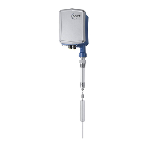
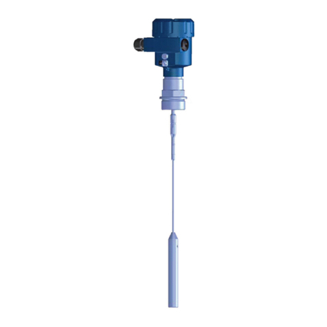
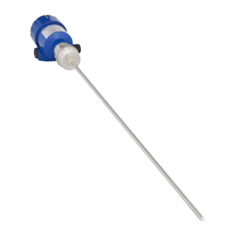
UWT Nivobob NB 3000 User manual

Nivobob®1
2
3
4
5
6
7
8
9
10
11
12
NB 3000 gi130109 1
Continuous level measuring system
NB 3000
Technical information / Instruction manual
page G
Table of contents
Page
Safety notes / Technical support G2
------------------------------------------------------------------------------------------------------
Introduction G3
------------------------------------------------------------------------------------------------------
Dimensions G4
------------------------------------------------------------------------------------------------------
Technical data Electrical Data G8
Mechanical Data G9
Operating conditions G10
Approvals G10
Sensor weight guide G11
------------------------------------------------------------------------------------------------------
Options / Accessories G12
------------------------------------------------------------------------------------------------------
Mounting G14
------------------------------------------------------------------------------------------------------
Electrical installation NB 3000 Nivobob G16
NB 9000 Remote Box G20
------------------------------------------------------------------------------------------------------
Signal overview G22
------------------------------------------------------------------------------------------------------
Programming NB 3000 Nivobob Quickset menu G24
Output adjustment menu G26
Diagnostics menu G29
Communication menu G31
Modbus register G32
------------------------------------------------------------------------------------------------------
Programming NB 9000 Remote Box G34
------------------------------------------------------------------------------------------------------
Commissioning Interface measurement G36
------------------------------------------------------------------------------------------------------
Diagnostics Maintenance G37
Failure G39
------------------------------------------------------------------------------------------------------
Notes for use in Hazardous Locations G40
Subject to technical change. We assume no liability for typing errors.
All dimensions in mm (inches). Different variations to those specified are possible.
Please contact our technical consultants.
All units in this information are CE-certified.

Nivobob®
1
2
3
4
5
6
7
8
9
10
11
12
NB 3000
gi130109
2
Continuous level measuring system
NB 3000
Technical information / Instruction manual
page G
Safety notes / Technical support
Notes
• Installation, maintenance and commissioning must be carried out only by qualied technical personnel.
• The product must be used only in the manner outlined in this instruction manual.
Special attention must be paid to warnings and notes as follows:
WARNING
Relates to a caution symbol on the product and means, that a failure to observe the necessary
precautions can result in death, serious injury and/or considerable material damage.
WARNING
Relates to a caution symbol on the product and means, that a failure to observe the necessary
precautions can result in death, serious injury and/or considerable material damage.
This symbol is used, when there is no corresponding caution symbol on the product.
A failure to observe the necessary precautions can result in considerable material damage.CAUTION
Safety symbols
In manual and on
product Description
CAUTION: refer to related documents (manual) for details.
Earth (ground) Terminal
Protective Conductor Terminal
Technical support
Please contact your local supplier (see www.uwt.de for address). Otherwise you can contact:
UWT GmbH Tel. 0049 (0)831 57123-0
Westendstr. 5 Fax. 0049 (0)831 76879
Germany www.uwt.de

Nivobob®1
2
3
4
5
6
7
8
9
10
11
12
NB 3000 gi130109 3
Continuous level measuring system
NB 3000
Technical information / Instruction manual
page G
Introduction
The Nivobob®NB 3000 is an electromechanic level measuring
instrument for continuous measuring of level or volumes in silos,
hoppers or tanks.
Applications
• Powder, granulate, small or coarse bulk goods
• Interface measurement (solids in water)
Applicable for industries such as
• Chemistry
• Food
• Cement
• Mining
• Plastics
• others
Features
Process
• Suitable for most types of bulk goods
• Independent of bulk material properties, such as:
Dielectricity and conductivity of the bulk good
Dusty atmosphere in the silo
Changing humidity inside the product
Products that tend to stick
• No mechanical load on the silo roof, the sensor weight
just touches the surface of the material
• Very accurate measurement
Service
• Simple installation and commissioning
• Measurement principle easy to understand
• Rope, tape and (optional) motor with increased service life
• Low maintenance
Approvals
• Approval for use in Hazardous Locations
ATEX II 1/2 D (zone 20/21) and FM Class. II, III Div.1 Gr. E-G
Mechanic
• Measurement range upto 40m (133ft)
• 1 1/2" process connection possible
• Different sensor weights, suitable for every application
• Internal tape cleaner for difficult materials
• Window in lid and external start button (optional)
• Robust cast housing, ingress protection IP66
Electronic
• Micro processor controlled measurement
• Remote Box for external programming, display of level and
diagnose, start of measurement of up to 10 Nivobob units
• Comprehensive Diagnose possibilities
• Output 0/4-20mA / Modbus / Profibus DP / counting pulses
• Programmable relais (can be used as level limit switch outputs)
• Measurement start with external signal or integrated timer
Function
The Nivobob® NB 3000 is mounted on the top of the silo. A sensor
weight is driven down into the silo. It is mounted at the end of a rope
or tape which is wound on a motor driven roller. Upon contact with
bulk material, the motor changes the winding direction and the sensor
weight is driven back to the upper stop position.
During downwards movement of the sensor weight the distance is
electronically measured by the rotations of the internal rope / tape
roller. The microcontroller converts the measured distance into an
output signal, which is a volumetric signal based on the silo geometry.
The output signal is updated, when the sensor weight touches the bulk
material.
Diagnostics
Comprehensive diagnostics possibilities are present:
• Measurement control is done by comparing the moved distance
between up and downward movement and checking for discrepancy.
In case of discrepancy, the sensor weight is pulled to the upper stop
position to ensure, that the sensor weight is not inside the silo.
• Service interval after a certain amount of measurements and running
time.
• Internal control of motor, motor driver electronic and smooth
movement of rope / tape rollers.
Diagnostics is in accordance with NAMUR recommendation NE107.
Nivobob®
1
2
3
4
5
6
7
8
9
10
11
12
NB 3000
gi130109
4
Continuous level measuring system
NB 3000
Technical information / Instruction manual
page G
Dimensions
X
Flange version
Basic type
Thread version
Flange version,
bottom view
X
A
A
C
C
B
B
B= Diameter of socket pipe
Rope version with
Flange DN100 / 4"
ø60mm (2.36")
All other versions ø40mm (1.57")
Socket
pipe
Socket
pipe
Flange Thread
Housing Housing
Housing
extension Housing
extension
Housing outside Aluminium, powder coated
Housing inside Aluminium
Housing extension Aluminium, powder coated or 1.4305 (303)
Flange 80°C / 150°C: Aluminium, powder coated
250°C: 1.4305 (303)
Thread 1.4301 (304)
Socket pipe Flange version 80°C / 150°C: Aluminium
All other versions: 1.4301 (304)
Rope 1.4301 (304)
Tape 1.4310 (301)
X= Length to bottom of sensor weight
(in upper stop position): see next page
A= Lenght of socket pipe
200mm (7.9")
Optional 500mm (19.7") / 1000mm (39.4")
C= Housing extension
Flange version 80°C / 150°C 95mm (3.74")
250°C 340mm (13.4")
Thread version 80°C / 150°C 160mm (6.3")
250°C 340mm (13.4")
Rope / tape Rope / tape
Dimensions
Materials
Rope ø1,25mm (0.49")
Tape 12x0.2mm (0.47x0.008")
With option "Increased corrosion resistance":
All metal parts in contact with the process are coated.
The rope is plastic coated with PA.
The internal bearings are made of stainless steel.
Lk
Flanges
fitting to:
DN100 PN16 / 4" 150lbs
Lk = ø90 .. 95.3mm (3.54 .. 3.75") slot
d2 = ø19mm (0.75")
fitting to:
2" / 3" 150lbs
Lk = ø60.4 .. 76.2mm (2.38 .. 3.0") slot
d2 = ø19mm (0.75")
d2

Nivobob®1
2
3
4
5
6
7
8
9
10
11
12
NB 3000 gi130109 5
Continuous level measuring system
NB 3000
Technical information / Instruction manual
page G
Dimensions
PVC without pin
Sensor weights
PVC with pin Stainless steel Claw
Folding cover
Spider
Bag
Float
Solids measurement: Rope version
All weights ca. 1,0kg (2.2lbs)
X
Ø81mm (3,2" )
X = 137mm (5.4")
Material: PVC
Version with
Flange DN100 / 4"
Ø75mm (3.0")
X = 25mm (1.0")
Pin: 130mm (5.1")
Ø95 (3.7")
X = 71mm (2.80")
Material: 1.4305 (304)
Ø81mm (3,2")
X = 137mm (5.4")
Pin: 130mm (5.1")
Material: PVC (pin POM)
X
X
X
X
X
X
X
X
380x380mm (15x15")
X = 150mm (5.9")
Material: 1.4310 (301)
PA canvas
Ø600mm (23.6")
X = 160mm (6.3")
Material: 1.4301 (304) /
1.4310 (301)
Ø190mm (7.5" )
X = 175mm (6.9")
Material: Float PP,
Cone: 1.4305 (304)
Ø95mm (3.7")
X = 460mm (18.1")
Material: PA canvas,
SS chain, alu cone
Options and Accessories
Pos. 28
Compressed air
connector
Pos. 25
Window in lid and
outside start button
Window in lid
Outside
start button
Compressed
air connector
All other versions
Ø42mm (Ø 1.65")
X = 81mm (3.19")
Pin: 130mm (5.1")
Material:
1.4305 (304)

Nivobob®
1
2
3
4
5
6
7
8
9
10
11
12
NB 3000
gi130109
6
Continuous level measuring system
NB 3000
Technical information / Instruction manual
page G
Dimensions
Interface measurement: Rope version
Weight ca. 1,0kg (2.2lbs)
Solids measurement: Tape version
All weights ca. 2.1kg (4.6lbs)
PVC with pin Stainless
steel Claw Folding
cover
Spider
Bag
Float
X
Ø42mm (Ø 1.65")
X = 320mm (12.6")
Pin: 130mm (5.1")
Material: 1.4305 (304)
Ø95 (3.7")
X = 236mm (9.3")
Material: 1.4305 (304)
Ø81mm (3,2")
X = 465mm (18.3")
Pin: 130mm (5.1")
Material: PVC (pin POM)
X
X
X
X
X
X
380x380mm (15x15")
X = 430mm (16.9")
Material: 1.4310 (301)
PA canvas
Ø600mm (23.6")
X = 345mm (13.6")
Material: 1.4301 (304) /
1.4310 (301)
Ø190mm (7.5" )
X = 285mm (11.2")
Material: Float PP
Ø95mm (3.7")
X = 575mm (22.6")
Material: PA canvas,
SS chain, alu xing
Aluminium
1.4305 (304)
Ø81mm (3,2" )
X = 82mm (3.2")
Material: PVC with plastic/metal disks
X
Interface measurement: Tape version
Weight ca. 2.1kg (4.6lbs)
Ø42mm (Ø 1.65")
X = 320mm (12.6")
Pin: 130mm (5.1")
Material: 1.4305 (304)
X
including additional disks to
adjust to the application

Nivobob®1
2
3
4
5
6
7
8
9
10
11
12
NB 3000 gi130109 7
Continuous level measuring system
NB 3000
Technical information / Instruction manual
page G
Dimensions
Depth 90mm (35.4")
NB 9000
Wall mounting
NB 9000
Panel mounting
AC/DC converter
Mounting holes
Biasing network Terminal plug
NB 9000 Remote Box
Mounting: DIN rail 35

Nivobob®
1
2
3
4
5
6
7
8
9
10
11
12
NB 3000
gi130109
8
Continuous level measuring system
NB 3000
Technical information / Instruction manual
page G
Technical data
Electrical data
Power supply AC version 98 .. 253V 50-60Hz
DC version 20 .. 28V
(voltages incl. 10% of EN 61010)
Installed load AC version: 150 VA (including internal heater (80W))
DC version:
One unit: 150W (with or without internal heater) *
Further units which are connected to the same power supply:
25W per unit (without internal heater, motor off) **
50W per unit (without internal heater, motor running)
80W per unit (with internal heater, supply voltage 20V DC)
100W per unit (with internal heater, supply voltage 24V DC)
120W per unit (with internal heater, supply voltage 28V DC)
*Considers the max. motor traction which is needed in a failure condition. A failure condition is assumed for
max. one unit at the same time.
** This value can be considered, if the controlling PLC starts the measurement for max. one unit at the same
time.
Signal output:
0/4-20mA
Max. 500 Ohms (active, isolated) Linearity +/- 0,1mA
Signal output:
Relay
4x Relay SPST:
max. 250V AC, 2A, 500VA non inductive
Signal output:
Electronic counting pulse
Optocoupler
max. 30V DC, max. 25mA
Communication:
Modbus RTU
Physical layer: RS 485 and Ground, isolated
Mode: RTU, Type: Slave
Device number range: 1 - 247 (selectable in menu), Baudrate: 1200 to 57600 Baud, Data bits: 8, Stop Bits: 1
Parity: None
Multi-drop configuration possible. Factory setting of adress is 100. Each unit which is connected to the
network must be set to an individual adress.
Supported commands
Reading: All diagnostics and parameters using command 03HEX: Read Holding Register
Writing: All parameters using command 06HEX: Write Single Register (not supported is command 10HEX: Write
Multiple Register).
Communication:
Profibus DP
Physical layer: RS 485, isolated
Type: Slave
Device number range: 0 - 126 (selectable in menue), Baudrate: 9.6 kbps to 12 Mbps
Available communication by GSD le, Read only (Sensor weight bottom to material (in mm))
Accuracy of measurement Output Setting Accuracy
Counting pulse 10cm (1/6ft) / pulse 1 pulse
5cm (1/3 ft) / pulse 1 pulse
2,5cm (1/10ft) / pulse 2 pulses
1cm (1/20ft) / pulse 4 pulses
0/4-20mA 1% of max. range
Modbus RTU / Profibus 0.5% of max. range
Display LCD display: 2 line x 16 digit
Indication light Status by build in LED: Power On, Relais, Maintenance and Failure

Nivobob®1
2
3
4
5
6
7
8
9
10
11
12
NB 3000 gi130109 9
Continuous level measuring system
NB 3000
Technical information / Instruction manual
page G
Technical data
Mechanical data
Ingress protection IP 66, Type 4
Process connection Threads: R 1 1/2" DIN 2999 tapered,
NPT 1 1/2" or 3" ANSI B1.20.1 tapered
Flanges: DN100 PN16 EN1092-1 (unit fits to this flange)
2" or 3" or 4" 150lbs ANSI B16.5 (unit ts to this ange)
Colour Housing, Flange RAL 5010 (gentian blue)
Lid RAL 9006 (aluminium silver)
Material See detail specifications on page G4 - G6
Measuring range Rope version max. 30m (100ft)
Tape version max. 40m (133ft)
Measuring speed Sensor weight speed in average:
Standard version: ca. 0.25m/s (0.8ft/sec)
Version with brushless motor: ca. 0.33m/s (1.0ft/sec)
Weight Rope version with flange: ca. 11kg (24.2lbs)
with thread: ca. 12kg (26.4lbs)
Tape version with flange: ca. 12kg (26.4lbs)
with thread: ca. 13kg (28.6lbs)
Deviation of vertical mounting max. 2°
Compressed air connector
(Option)
Quick coupling incl. opposite part, for hose diameter 9mm (0.35“), female at housing
Max. operating pressure 0.2bar (2.9psi)
Memory Non-volatile (no backup battery required) > 10 years data retention
Connection terminals 0.14 .. 2.5mm2(AWG 26 .. 14)
Cable entry According to selection:
Screwed cable gland: 2x M20x1.5 and 1x M25x1.5 Blindplug: 2x M20x1.5 or
Conduit ANSI B1.20.1: 1x NPT 3/4"+ 2x NPT 1/2" Blindplug: 2x NPT 1/2"
Extension cables for Remote
Box NB 9000 and Modbus
Specications see in chapter "Electrical installation"
Suggested cable types see in chapter "Accessories"
Extension cables for
Profibus DP
Use common recommended Profibus cables
Isolation Power supply to all other outputs / inputs: AC version 2210 Vrms
DC version: 1000 VDC
Relay to relay: 2210 Vrms
Protection class I

Nivobob®
1
2
3
4
5
6
7
8
9
10
11
12
NB 3000
gi130109
10
Continuous level measuring system
NB 3000
Technical information / Instruction manual
page G
Operating conditions
Process overpressure -0.3 ..+0.3bar (-4.4 ..+4.4psi)
-0.5 .. + 1.7 bar (-7.3 .. +25psi) optional
Process temperature -40°C ..+80 /150 / 250°C (-40 ..+176 / 302 / 482°F)
Ambient temperature -20°C .. +60°C (-4 .. +140°F)
-40°C .. +60°C (-40 .. +140°F) CE, FM General Purpose with internal heater
-40°C .. +60°C (-40 .. +140°F) ATEX, FM Class II on request possible
max. +40°C (104°F) Version with Process temp. 150°C (302°F)
Min. powder density see "Sensor weight guide" on next page
Minimum time between
measuring starts
measuring height 5m (16ft )-> 3min
measuring height 10m (33ft) -> 6min
measuring height 20m (66ft) -> 12min
measuring height 30m (98ft) -> 18min
measuring height 40m (131ft) -> 24min
Rope/tape operating time see page G38
Max. permitted tractive force Tape version: with brushless motor: ca. 3000N
standard motor: ca. 800N
Rope version: with brushless motor: ca. 1000N
standard motor: ca. 800N
with increased corrosion resistance: ca. 700N
Relative humidity 0-100%, suitable for outdoor
Altitude max. 2000m (6.562ft)
Technical data
Approvals
Hazardous Locations* ATEX II 1/2 D (zone 20/21)
FM Class. II, III Div.1 Gr. E-G
General purpose * CE EN 61010-1
FM General purpose
EMC EN 61326 -A1 (industrial standard)
* Depending on selected version in pricelist

Nivobob®1
2
3
4
5
6
7
8
9
10
11
12
NB 3000 gi130109 11
Continuous level measuring system
NB 3000
Technical information / Instruction manual
page G
Sensor weight guide (solids measurement)
Technical data
Sensor weight Application Note Fits through mounting
hole
* Material
densitiy
g/l (lb/ft3)
Material
consistence
Angle of
repose
Max.
process
temp.
Thread Flange
1
1/2"
3" 2" 3" DN100
/ 4"
PVC
witout pin
>300
(18)
granulate flat 80°C
(176°F)
Standard weight •
PVC
with pin
>300
(18)
granulate,
powder
steep 80°C
(176°F)
The pin penetrates into the material and avoids
slipping or tilting of the sensor weight on the
steep bulk surface.
•
Stainl. steel >300
(18)
granulate,
powder
at, steep 250°C
(482°F)
The pin penetrates into the material and avoids
slipping or tilting of the sensor weight on the
steep bulk surface.
• • • • •
Claw >200
(12)
coarse (e.g.
stones)
steep 250°C
(482°F)
Avoids slipping or tilting on the steep bulk
surface.
•
Folding cover >20
(1.2)
light powder at, steep 80°C
(176°F)
Big surface prevents the sensor weight from
sinking into the material.
• • • • •
Spider >40
(1.4)
light powder at, steep 250°C
(482°F)
Big surface prevents the sensor weight from
sinking into the material.
•
Bag >300
(18)
granulate,
powder
flat 80°C
(176°F)
Prevents damage of the conveying screw. To
be filled with bulk material.
•
Float -liquids only - 80°C
(176°F)
To be filled with material.
PVC
without pin
Stainless
steel
Claw
Folding
cover
Spider
Bag
Float
PVC
with pin
* The above mentioned data is a guideline and is valid for material which has settled after filling.
During the filling the bulk density can change (e. g. for fluidised material).

Nivobob®
1
2
3
4
5
6
7
8
9
10
11
12
NB 3000
gi130109
12
Continuous level measuring system
NB 3000
Technical information / Instruction manual
page G
Options / Accessories
Options
Window in lid and
external start button
Enables to see the display through the closed lid and to
start a measurement without opening the lid.
Material of the window: break-proof glass.
Drawing see page G5
Accessories
NB 9000 Remote box
(Panel mounting)
Connecting up to 10 units with Modbus RTU network.
Features:
• Programming of the Nivobob units
• Display of level
• Start of measurement
• Display of diagnostics information
Technical data:
• NB 9000 works as a Modbus master
• Touchpanel
• Power supply: 24V DC +-10% 10W or
85 .. 264V +-0% 50-60Hz 10VA
• Ambient temperature: -0 .. +50°C (-32 .. +122°F)
• Ingress protection: IP65
• Installation only in Non-Hazardous areas permitted
Included parts:
For easy installation and proper functioning of the
Modbus network
• Biasing network (with Terminal resistor):
Stabilizer for Modbus communication.
Supports the needed biasing voltages to ensure a proper
function in a network with long installed cables.
Termination resistor is needed for the beginning of the
Modbus network.
• Terminal Plug
Supplies screwing terminals for connection between NB
9000 panel and Biasing network
• AC/DC converter
Used, if AC power supply is selected
NB 9000 Remote Box
(Wall mounting)
Implementation of NB 9000 panel in a wall mounted
enclosure.
Material: PC (fibre glas reinforced)
Biasing network (with Termination resistor) implemented.
AC/DC converter (if AC power supply is selected)
implemented.
AC/DC converter
Biasing network Terminal Plug
NB 9000 Panel
DIN rail 35
mounting
DIN rail 35
mounting

Nivobob®1
2
3
4
5
6
7
8
9
10
11
12
NB 3000 gi130109 13
Continuous level measuring system
NB 3000
Technical information / Instruction manual
page G
Accessories
Extension cables •For connecting the Remote Box NB 9000
•For wiring a Modbus network
• Notes for choosing the right cable see chapter "Electrical Installation"
•It is generally recommended to protect PVC signal cables from UV influence by installing them in a pipe or hose.
Shielded cable
Functionality upto 50m
Cross section 2x 0,34mm2 (AWG22), common shield
Capacitance 140nF/km (between wires) / 150nF/km (wire to shield)
-30°C (-22°F) to 70°C (158°F), PVC (LiYCY)
Twisted pair cable
Functionality upto 1000m
Twisted pair instrument cable, common shield
Cross section 2x 0,34mm2(AWG22)
Impedance 120 Ohms
Capacitance 40nF/km
-40°C (-40°F) to 75°C (167°F), PVC
Protection hose
for installation of extension cables in ATEX Zone 21 available
Weather protection cover If the unit is used outdoors, the use of the weather
protection cover is recommended. It protects the device
from all atmospheric influences such as
• rain water
• condensation water
• excessively high temperatures
• excessively low temperatures in winter
Material: PE, weather and temperature stable
For use in Hazardous Locations only permitted for Zone
22 or Division 2.
Mounting set Sealings, screws and washers for xing the unit on a
flange.

Nivobob®
1
2
3
4
5
6
7
8
9
10
11
12
NB 3000
gi130109
14
Continuous level measuring system
NB 3000
Technical information / Instruction manual
page G
Mounting
General Safety Instructions
Process pressure Improper installation may result in loss of process pressure.
Chemical resistance
against the medium
Materials of construction are chosen based on their chemical compatibility (or inertness) for general purposes.
For exposure to specic environments, check with chemical compatibility charts before installing.
Mounting location The right mounting place is significant for a proper function. Observe mounting instructions.
Vibrations Avoid mounting in applications with strong vibration. Use rubber mounts for absorption in case of light
vibrations.
Mounting instructions
Mounting position • The unit is mounted vertically on the silo. Max. deviation is 2°.
• There must be at least 200mm (7.87“) space for the sensor weight to move down in case of a full silo.
Observe the bottom of the sensor weight at "upper stop position" (dimensions see page G4 - G6).
Additional Safety Instructions for Hazardous Locations
Installation regulations For devices to be used in Hazardous Locations the respective valid installation regulations must be observed.
Sparks The installation has to be done in a way, that mechanical friction or impact does not cause sparks between
the aluminium enclosure and steel.
• The socket pipe of the unit must
protude at least 50mm (2") into
the silo. A version with longer
socket pipe is available.
• Proper movement of the sensor weight must be
guaranteed, even if the sensor weight oscillates.
Observe enough distance to the silo wall, stanchions
and built-in fittings.

Nivobob®1
2
3
4
5
6
7
8
9
10
11
12
NB 3000 gi130109 15
Continuous level measuring system
NB 3000
Technical information / Instruction manual
page G
Mounting
Measurement during filling
of the silo
Filling of the silo while measuring might cover the sensor weight with bulk material. Measurements during filling
are possible, if there is enough distance to the infeed, so that no material can fall on the sensor weight.
Sensor weight
"Bag" and "Float"
• The weights are lled with plastic granulate or sand. They shall be lled on site with bulk material or liquid,
which is not critical if mixed with the material stored in the silo. Consider ageing of the material.
• When lling, observe the total weigth of the sensor: rope version 1.0kg (2.2lbs), tape version 2.1kg (4.6lbs)
Sealing • A rubber seal must be used to tighten the ange.
• Close both lids of the enclosure tightly.
Sensor weight which
does not fit through
the mounting hole
The sensor weight must be removed before
placing the unit on the silo. An inlet close to the fixing
loacation and a hook is needed.
See installation manual for more details. Hook

Nivobob®
1
2
3
4
5
6
7
8
9
10
11
12
NB 3000
gi130109
16
Continuous level measuring system
NB 3000
Technical information / Instruction manual
page G
Electrical installation
Handling In case of improper handling or handling malpractice, the electric safety of the device cannot be guaranteed.
Installation regulations The local regulations or VDE 0100 (Regulations of German Electrotechnical Engineers) must be observed.
Fuse Use a fuse as stated in the connection diagrams.
RCCB protection In case of a fault, the supply voltage must be automatically switched off by a RCCB protection switch to
protect against indirect contact with dangerous voltages.
Power supply switch A voltage disconnection switch must be provided near the device.
Wiring diagram The electrical connections are made in accordance with the wiring diagram.
Supply voltage Compare the supply voltage applied with the specifications given on the name plate before switching the
device on.
Cable gland Make sure that the screwed cable gland safely seals the cable and that it is tight (danger of water intrusion).
Cable glands that are not used have to be sealed with a blanking element.
Conduit system In case of using a conduit system (with NPT thread) instead of a cable gland the regulations of the country,
where the unit is installed, must be observed. The conduit must have a tapered thread either NPT 1/2“ or
NPT 3/4” in accordance with the unit and ANSI B 1.20.1. Not used inlets must be closed tight with a metal
blanking element.
Field wiring cables All field wirings must have insulation suitable for at least 250V AC. The temperature rating must be at least
80°C (176°F).
Relay protection Provide protection for relay contacts to protect the device against inductive load surges.
Protection against static
charging
The housing of the unit must be grounded to avoid static charging of the unit. This is particularly important
for applications with pneumatic conveying and non-metallic containers.
General Safety Instructions
External equipotential
bonding terminal
Field wiring A strain relief must be provided for the eld wiring cables, if the device is installed with the factory provided
cable glands.
Cable glands for ATEX
Hazardous Locations
The used entry devices and blanking elements must have an adequate type approval and a temperature
range as defined in the technical data of the unit. In addition they shall be suitable for the conditions and
correctly installed. Where applicable the provided original parts of the manufacturer must be used.
Conduit system for
ATEX and FM
Hazardous Locations
In addition the regulations of the country must be observed. The used flameproof seals and blanking
elements must have an adequate type approval and a temperature range as dened in the technical data
of the unit. In addition they shall be suitable for the conditions and correctly installed. Where applicable the
provided original parts of the manufacturer must be used.
Comissioning / opening the
lid
Comissioning only, when there are no dust deposits or swirls present.
Additional Safety Instructions for Hazardous Locations
Connect to equipotential
bonding of the plant

Nivobob®1
2
3
4
5
6
7
8
9
10
11
12
NB 3000 gi130109 17
Continuous level measuring system
NB 3000
Technical information / Instruction manual
page G
Electrical installation
Relais
Power
supply
0/4-20mA
Modbus RTU
Profibus DP
Start input
El. counting pulse
Terminal location
NB 3000 - Power supply and Signal input /output
Display
Protective
conductor
terminal
Full detector input
Power supply
Signal input:
Start of measurement
98 .. 253V 50-60Hz 20-28V DC
AC or DC supply
depending on
ordered version
DC version
AC version
Start contact Start +24V
alternative
Signal
description:
See page G22
Measurement interruption in
case of lling. If used, remove
factory provided connection.
0.14 .. 2.5mm2
(AWG 26 .. 14)
0.14 .. 2.5mm2
(AWG 26 .. 14)

Nivobob®
1
2
3
4
5
6
7
8
9
10
11
12
NB 3000
gi130109
18
Continuous level measuring system
NB 3000
Technical information / Instruction manual
page G
Electrical installation
Signal input:
Full detector
Signal output:
0/4-20mA
Signal output:
Relay
Signal output:
Electronic counting pulse
max. 500 Ohm
Relay1
max. 250V AC, 2A, 500VA, non inductive
Fuse: max. 2A
max. 30V DC, max. 25mA
Fuse: max. 63mA
Optocoupler Note:
Reset pulse is done with Relay 2
Signal
description:
See page G22
Signal
description:
See page G22
Relay2 Relay3 Relay4
Signal
description:
See page G23
active, isolated
Signal
description:
See page G22
0.14 .. 2.5mm2
(AWG 26 .. 14)
0.14 .. 2.5mm2
(AWG 26 .. 14)
0.14 .. 2.5mm2
(AWG 26 .. 14)
0.14 .. 2.5mm2
(AWG 26 .. 14)

Nivobob®1
2
3
4
5
6
7
8
9
10
11
12
NB 3000 gi130109 19
Continuous level measuring system
NB 3000
Technical information / Instruction manual
page G
Electrical installation
NB 3000 - Modbus network
Setting Biasing and
Termination Resistor
For use of NB 3000 units in a
external Modbus network, it
is possible to set Biasing and
Termination Resistor on each
unit as required.
NB 3000 - Profibus DP network
*factory provided
Biasing OFF* OFF ON
Termination
Resistor
OFF* ON ON
Wiring according to Profibus
DP standards

Nivobob®
1
2
3
4
5
6
7
8
9
10
11
12
NB 3000
gi130109
20
Continuous level measuring system
NB 3000
Technical information / Instruction manual
page G
Electrical installation
Remote Box NB 9000 - Internal wiring and power supply
Panel mounting
version
24V DC
85 .. 264V
50-60Hz alternative*
Terminal plug to
be connected to
COM1
NB 9000 panel
Wall mounting
version
Biasing
network
24V DC
85 .. 264V
50-60Hz alternative* * AC/DC converter:
Used, if AC power supply is
selected
Biasing
network
Connections to NB 9000 panel
are factory provided
Terminal 3-5:
Modbus connections to
NB 3000 units (see next
page)
Fuse 0,63A .. 1,6A
Fuse 0,63A .. 1,6A
Use shielded cable
* AC/DC converter:
Used, if AC power supply is
selected
If required: Power supply can
be taken from one of the NB
3000 power supply terminals
(see next page).
If required: Power supply can
be taken from one of the NB
3000 power supply terminals
(see next page).
Note:
Terminal
plug internal
connections:
Pin 1 and 4.
Pin 8 and 9.
Terminal 3-5:
Modbus connections to
NB 3000 units (see next
page)
Note:
NB 9000 COM1:
Modbus D1 =
Pin 1 and 4.
Modbus D0 =
Pin 8 and 9.
Cache = shield.
Other manuals for Nivobob NB 3000
1
Table of contents
Other UWT Measuring Instrument manuals

UWT
UWT NivoRadar NR 7200 Series User manual

UWT
UWT NivoRadar NR 4100 Series User manual

UWT
UWT NivoGuide 8100 User manual

UWT
UWT NivoRadar NR 7200 Series User manual

UWT
UWT NivoRadar NR 7100 Series User manual

UWT
UWT NG 8100 User manual

UWT
UWT NivoRadar NR 7100 Series User manual

UWT
UWT NivoRadar NR 7000 Series User manual

UWT
UWT Nivo Radar NR 4000 Series User manual

UWT
UWT Rotonivo RN 3000 User manual