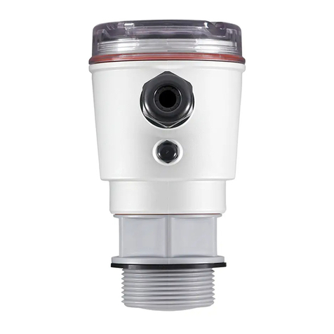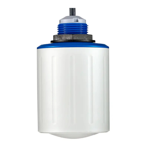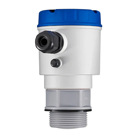
Level monitoring system
NT 4500
Technical information / Instruction manual
page
Commissioning
2. Check the wiring
Make sure that the Modbus network is wired, set the Modbus Termination Resistor (and for NB 3000/ NB 4000 the Biasing), check that
the Ethernet connection is available (see "Electrical installation" from page 5 onwards).
Note: All units are presetted to 19200 Baud. Thus no setting is required.
3. Web server conguration
CAUTION: The conguration should be done by the network administrator only.
The web server is preset to the IP address 192.168.10.70. It must be changed to a company's own IP address as follows:
• Use a PC, which is connected via Ethernet to the Web server. Set in the system control the TCP/ IP to address 192.168.10.xxx,
whereas xxx can be any number between 0 and 255 (the access to the Web server requires the number 192.168.10., the last
numberblock is not relevant).
• An up to date version of Internet browser must be installed.
• Open the Internet browser and type the IP address 192.168.10.70 of the web server in the command bar. The overview page
"Home" of the visualisation opens (see page 11).
• Click the "Login" button and set the user name to "Admin" with the password "admin". The "System Cong" button will appear in the
menu bar.
• Click on this button. The conguration page of the web server will open (see page13ff.).
• Enter the number of silos, language, date and time, your IP address, sub net mask and gateway.
• Then reset to your TCP/ IP address in the system control of your PC.
4. Perform the basic settings of the connected sensors
With the following settings, the connected sensors are addressed via the visualisation and give a real measurement result. For this
settings the above mentioned synoptical table is helpful. On the overview page "Home", click into the desired silo. There you have to edit
the following settings:
• On page "Setup" (see page17f.) the data under "Silo Data", "Modbus RTU" and "Level Limit Sensor".
• On page "Volume Calculation" (see page19) the data under "Silo Shape" and "Silo Data".
5. Perform further user settings
Enter the required user specic settings according to the "Visualisation - Operation" from page 11 onwards.
1. Generation of a synoptical table
Commissioning is facilitated if an overview of the connected sensors is made in advance.
The table shows an example of a project with 11 silos and mixed conguration of Nivobob NB 3000 and NR 3000 radar
as well as implementation of full detectors:
Silo Sensor Modbus
ID
Modbus converter
Channel*
Modbus converter
Terminal of
sensor
Modbus converter
Terminal of full
detector
1NB 3000 3 n/ a n/ a n/ a
2NB 3000 4 n/ a n/ a n/ a
3NB 3000 5 n/ a n/ a n/ a
4NB 3000 6 n/ a n/ a n/ a
5NR 3000 1 0 Vin0+ DI0
6NR 3000 1 1 Vin1+ DI1
7NR 3000 1 2 Vin2+ DI2
8NR 3000 1 3 Vin3+ DI3
9NR 3000 2 0 Vin0+ DI0
10 NR 3000 2 1 Vin1+ DI1
11 NR3000 2 2 Vin2+ DI2
* see page17f. under "Modbus RTU"/ "Full Detector"
Nivotec®
1
2
3
4
5
6
7
8
9
10
11
12
NT4500
gi010218
10
