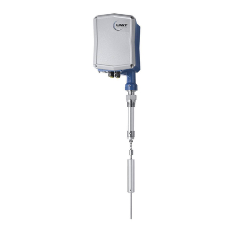
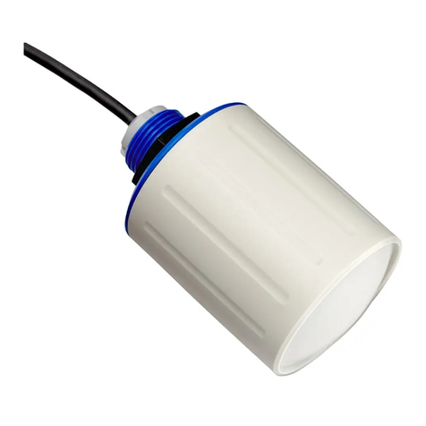
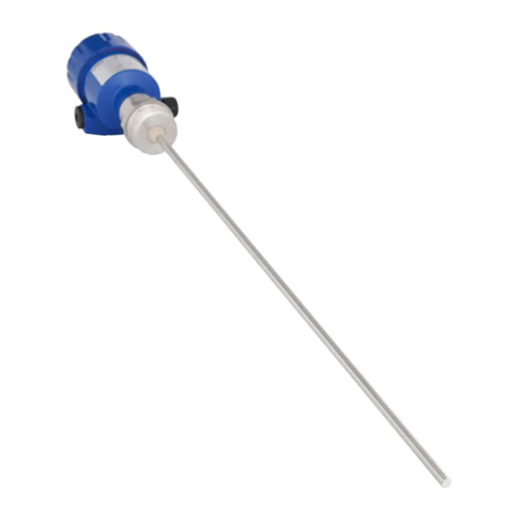
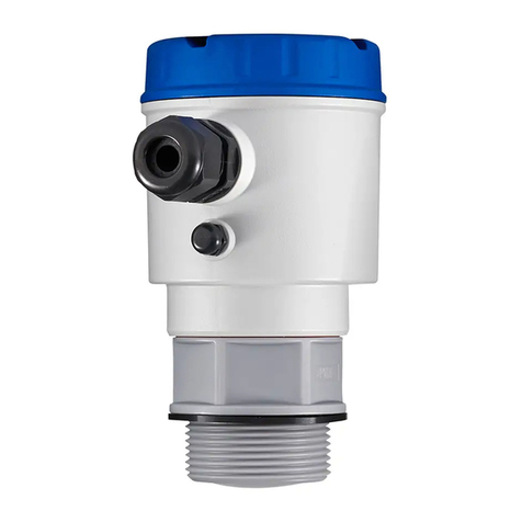
UWT NivoGuide 3100 User manual

Nivo®Guide 3100
Two-wire 4 … 20 mA/HART
Rod and cable probe
TDR sensor for continuous level measurement of bulk
solids
Quick setup guide
Document ID: 61268

2
Nivo®Guide 3100 • Two-wire 4 … 20 mA/HART
Contents
61268-EN-190215
Contents
1 For your safety ......................................................................................................................... 3
1.1 Authorised personnel .......................................................................................................3
1.2 Appropriate use................................................................................................................ 3
1.3 Warning about incorrect use............................................................................................. 3
1.4 General safety instructions............................................................................................... 3
1.5 EU conformity................................................................................................................... 4
1.6 NAMUR recommendations .............................................................................................. 4
2 Product description ................................................................................................................. 5
ʿƖʾ ÇÆŲ¿ÍʹÌÁÇÆ.................................................................................................................... 5
3 Mounting................................................................................................................................... 6
3.1 General instructions for use of the instrument .................................................................. 6
3.2 Mounting instructions ....................................................................................................... 6
4 Connecting to power supply................................................................................................. 10
4.1 Connecting..................................................................................................................... 10
4.2 Wiring plan, single chamber housing.............................................................................. 11
4.3 Wiring plan, double chamber housing ............................................................................ 11
5 Set up with the display and adjustment module ................................................................ 13
5.1 Insert display and adjustment module............................................................................ 13
5.2 Parameter adjustment - Quick setup .............................................................................. 14
6 Supplement ............................................................................................................................ 16
6.1 Technical data ................................................................................................................ 16
Information:
This quick setup guide enables quick setup and commissioning of
your instrument.
ÇÍ»¹ÆŲƼ¾ÍÊÌÀ½ÊÁƾÇÊŹÌÁÇÆÁÆÌÀ½»ÇÊʽËÈÇÆ¼ÁÆ¿Ɠ»ÇÅÈʽÀ½ÆËÁν
operating instructions as well as in the Safety Manual for instruments
ÏÁÌÀÉ͹ÄÁŲ»¹ÌÁÇÆƖ
Operating instructions NivoGuide 3100 - 4 … 20 mA/HART -
Two-wire - Rod and cable probe: Document-ID 58879
Editing status of the quick setup guide: 2019-02-12

3
Nivo®Guide 3100 • Two-wire 4 … 20 mA/HART
1 For your safety
61268-EN-190215
1 For your safety
1.1 Authorised personnel
All operations described in this documentation must be carried out
ÇÆÄѺÑÌʹÁƽ¼ƓÉ͹ÄÁŲ½¼È½ÊËÇÆÆ½Ä¹ÍÌÀÇÊÁ˽¼ºÑÌÀ½ÈĹÆÌÇȽʹÌÇÊƖ
During work on and with the device, the required personal protective
equipment must always be worn.
1.2 Appropriate use
NivoGuide 3100 is a sensor for continuous level measurement.
ÇÍ»¹ÆŲƼ¼½Ì¹ÁĽ¼ÁƾÇÊŹÌÁÇÆ¹ºÇÍÌÌÀ½¹Ê½¹Ç¾¹ÈÈÄÁ»¹ÌÁÇÆÁÆ
chapter "Product description".
Operational reliability is ensured only if the instrument is properly
Í˽¼¹»»ÇʼÁÆ¿ÌÇÌÀ½ËȽ»ÁŲ»¹ÌÁÇÆËÁÆÌÀ½ÇȽʹÌÁÆ¿ÁÆËÌÊÍ»ÌÁÇÆË
manual as well as possible supplementary instructions.
1.3 Warning about incorrect use
Inappropriate or incorrect use of this product can give rise to applica-
ÌÁÇÆƘËȽ»ÁŲ»À¹Ò¹Ê¼ËƓ½Ɩ¿ƖνË˽ÄÇνÊŲÄÄÌÀÊÇÍ¿ÀÁÆ»ÇÊʽ»ÌÅÇÍÆÌÁÆ¿
or adjustment. Damage to property and persons or environmental
contamination can result. Also, the protective characteristics of the
instrument can be impaired.
1.4 General safety instructions
This is a state-of-the-art instrument complying with all prevailing
regulations and directives. The instrument must only be operated in a
̽»ÀÆÁ»¹ÄÄÑŴ¹ÏĽË˹ƼʽÄÁ¹ºÄ½»ÇƼÁÌÁÇÆƖÀ½ÇȽʹÌÇÊÁËʽËÈÇÆËÁ-
ble for the trouble-free operation of the instrument.When measuring
aggressive or corrosive media that can cause a dangerous situation
if the instrument malfunctions, the operator has to implement suitable
measures to make sure the instrument is functioning properly.
During the entire duration of use, the user is obliged to determine the
compliance of the necessary occupational safety measures with the
current valid rules and regulations and also take note of new regula-
tions.
The safety instructions in this operating instructions manual, the na-
tional installation standards as well as the valid safety regulations and
accident prevention rules must be observed by the user.
For safety and warranty reasons, any invasive work on the device
beyond that described in the operating instructions manual may be
carried out only by personnel authorised by the manufacturer. Arbi-
ÌʹÊÑ»ÇÆÎ½ÊËÁÇÆËÇÊÅǼÁŲ»¹ÌÁÇÆË¹Ê½½ÐÈÄÁ»ÁÌÄѾÇʺÁ¼¼½ÆƖÇÊ˹¾½ÌÑ
ʽ¹ËÇÆËƓÇÆÄÑÌÀ½¹»»½ËËÇÊÑËȽ»ÁŲ½¼ºÑÌÀ½Å¹ÆÍ¾¹»ÌÍʽÊÅÍË̺½
used.
To avoid any danger, the safety approval markings and safety tips on
the device must also be observed and their meaning read in this oper-
ating instructions manual.
4
Nivo®Guide 3100 • Two-wire 4 … 20 mA/HART
1 For your safety
61268-EN-190215
1.5 EU conformity
À½¼½ÎÁ»½¾ÍÄŲÄËÌÀ½Ä½¿¹ÄʽÉÍÁʽŽÆÌËǾÌÀ½¹ÈÈÄÁ»¹ºÄ½¼Áʽ»-
ÌÁνËƖѹűÐÁÆ¿ÌÀ½Å¹ÊÃÁÆ¿ƓϽ»ÇÆŲÊÅÌÀ½»ÇƾÇÊÅÁÌÑǾÌÀ½
instrument with these directives.
1.6 NAMUR recommendations
NAMUR is the automation technology user association in the process
industry in Germany.The published NAMUR recommendations are
¹»»½È̽¼¹ËÌÀ½Ë̹Ƽ¹Ê¼ÁÆŲ½Ä¼ÁÆËÌÊÍŽÆÌ¹ÌÁÇÆƖ
À½¼½ÎÁ»½¾ÍÄŲÄËÌÀ½Ê½ÉÍÁʽŽÆÌËǾÌÀ½¾ÇÄÄÇÏÁƿʽ»ÇÅ-
mendations:
• NE 21 – Electromagnetic compatibility of equipment
• NE 43 – Signal level for fault information from measuring transduc-
ers
• ˂ˀƱÇÅȹÌÁºÁÄÁÌÑÇ¾Ų½Ä¼¼½ÎÁ»½Ë¹Æ¼¼ÁËÈĹÑƯ¹¼ÂÍËÌŽÆÌ
components
• ʾʽ˄Ʊ½Ä¾ƘÅÇÆÁÌÇÊÁÆ¿¹Æ¼¼Á¹¿ÆÇËÁËÇ¾Ų½Ä¼¼½ÎÁ»½Ë
For further information see www.namur.de.

5
Nivo®Guide 3100 • Two-wire 4 … 20 mA/HART
2 Product description
61268-EN-190215
2 Product description
ʿƖʾ ÇÆŲ¿ÍʹÌÁÇÆ
À½ÌÑȽĹº½Ä»ÇÆÌ¹ÁÆËÌÀ½ÅÇËÌÁÅÈÇÊ̹ÆÌ¼¹Ì¹¾ÇÊÁ¼½ÆÌÁŲ»¹ÌÁÇÆ¹Æ¼
use of the instrument:
2
1
12
13
14
11
10
5
3
6
4
7
8
9
Fig. 1: Layout of the type label (example)
1 Instrument type
2 Product code
3 Approvals (option)
4 Power supply and signal output, electronics
5 Protection rating
6 Probe length (measurement accuracy optional)
7 Process and ambient temperature, process pressure
8 Material wetted parts
9 Order number
10 Serial number of the instrument
11 Symbol of the device protection class
12 ID numbers, instrument documentation
ʾˀ Á¼½ÆÌÁŲ»¹ÌÁÇÆ
14 Approval directives (optional)
Type label

6
Nivo®Guide 3100 • Two-wire 4 … 20 mA/HART
3 Mounting
61268-EN-190215
3 Mounting
3.1 General instructions for use of the instrument
Protect your instrument against moisture ingress through the following
measures:
• Use a suitable connection cable (see chapter "Connecting to
power supply")
• Tighten the cable gland or plug connector
• À½ÆÅÇÍÆÌÁÆ¿ÀÇÊÁÒÇÆÌ¹ÄÄÑƓÌÍÊÆÌÀ½ÀÇÍËÁÆ¿ËÇÌÀ¹ÌÌÀ½»¹ºÄ½
gland or plug connector point downward
• Lead the connection cable downward in front of the cable entry or
plug connector.
This applies mainly to outdoor installations, in areas where high
ÀÍÅÁ¼ÁÌÑÁ˽ÐȽ»Ì½¼Ƽ½Ɩ¿ƖÌÀÊÇÍ¿À»Ä½¹ÆÁÆ¿ÈÊÇ»½Ë˽Ëƽ¹Æ¼ÇÆ»ÇÇĽ¼
or heated vessels.
To maintain the housing protection, make sure that the housing lid is
closed during operation and locked, if necessary.
¹Ã½ËÍʽÌÀ¹ÌÌÀ½¼½¿Ê½½Ç¾»ÇÆÌ¹ÅÁƹÌÁÇÆËȽ»ÁŲ½¼ÁÆ»À¹È̽Ê
"Technical dataͷ޽ÌËÌÀ½½ÐÁËÌÁÆ¿¹ÅºÁ½ÆÌ»ÇƼÁÌÁÇÆËƖ
3.2 Mounting instructions
Mount NivoGuide 3100 in such a way that the distance to vessel
installations or to the vessel wall is at least 300 mm (12 in). In non-
metallic vessels, the distance to the vessel wall should be at least
500 mm (19.7 in).
During operation, the probe must not touch any installations or the
vessel wall. If necessary, fasten the probe end.
In vessels with conical bottom it can be advantageous to mount the
sensor in the center of the vessel, as measurement is then possible
nearly down to the lowest point of the bottom. Keep in mind that
measurement all the way down to the tip of the probe may not be pos-
ËÁºÄ½ƖÀ½½Ð¹»ÌιÄͽǾÌÀ½ÅÁÆƖ¼ÁË̹ƻ½ƼÄÇϽʼ½¹¼º¹Æ¼ƽÁËË̹̽¼
in chapter "Technical data" of the operating instructions.
Fig. 2: Vessel with conical bottom
Plastic vessel/Glass vessel
The guided microwave principle requires a metallic surface on the
ÈÊÇ»½ËËŲÌÌÁÆ¿ƖÀ½Ê½¾ÇʽƓÁÆÈĹËÌÁ»Î½Ë˽ÄËƓ½Ì»ƖƓÍ˽¹ÆÁÆËÌÊÍ-
Protection against mois-
ture
Installation position
Type of vessel

7
Nivo®Guide 3100 • Two-wire 4 … 20 mA/HART
3 Mounting
61268-EN-190215
ŽÆÌνÊËÁÇÆÏÁÌÀŴ¹Æ¿½Ƽ¾ÊÇÅ˂ʽƽÇÊÈĹ»½¹Å½Ì¹ÄËÀ½½Ì
ƼĺʿʽʽÅÅƯ˅ÁÆƽº½Æ½¹ÌÀÌÀ½ÈÊÇ»½ËËŲÌÌÁÆ¿ÏÀ½ÆË»Ê½ÏÁÆ¿ÁÌÁÆƖ
¹Ã½ËÍʽÌÀ¹ÌÌÀ½ÈĹ̽À¹Ë¼Áʽ»Ì»ÇÆÌ¹»ÌÏÁÌÀÌÀ½ÈÊÇ»½ËËŲÌÌÁÆ¿Ɩ
When using the probes without metal vessel wall, e.g. in plastic
νË˽ÄËƓÌÀ½Å½¹ËÍʽ¼Î¹Äͽ»¹Æº½ÁÆŴͽƻ½¼ºÑËÌÊÇÆ¿½Ä½»ÌÊÇŹ¿-
ƽÌÁ»Ų½Ä¼ËƼ½ÅÁÌ̽¼ÁÆÌ½Ê¾½Ê½Æ»½¹»»ÇʼÁÆ¿ÌÇ˃ʾˀʿ˃ƕ»Ä¹ËËƽƖ
˽¹ÈÊǺ½ÁƻǹÐνÊËÁÇÆ¾ÇʹÈÈÄÁ»¹ÌÁÇÆËÁÆÄÁÉÍÁ¼ËƖ
1 2
Fig. 3: Mounting in non-metallic vessel
1 Flange
2 Metal sheet
Concrete vessel
When mounting in thick concrete ceilings, NivoGuide 3100 should be
ÅÇÍÆÌ½¼¾ÊÇÆÌŴÍËÀÌÇÌÀ½ÄÇϽʽ¼¿½ƖÆ»ÇÆ»Ê½Ì½ËÁÄÇËƓÌÀ½¼ÁË̹ƻ½
to the wall should be at least 500 mm (20 in).

8
Nivo®Guide 3100 • Two-wire 4 … 20 mA/HART
3 Mounting
61268-EN-190215
ø >160mm
(ø >6.3")
Fig. 4: Mounting in concrete silo
¾ÈÇËËÁºÄ½Ɠ¹ÎÇÁ¼ËǻýÌËƖÇÍÆÌÌÀ½Ë½ÆËÇÊŴÍËÀÏÁÌÀÌÀ½Î½Ë˽ÄÌÇÈƖ
If this is not possible, use short sockets with small diameter.
Higher sockets or sockets with a bigger diameter can generally be
used.They can, however, increase the upper blocking distance (dead
band). Check if this is relevant for your measurement.
In such cases, always carry out a false signal suppression after
ÅÇÍÆÌÁÆ¿ƖÇÍ»¹ÆŲƼ¾ÍÊÌÀ½ÊÁƾÇÊŹÌÁÇÆÍÆ¼½ÊͷSetup procedure".
21
12
11
1
Fig. 5: Mounting socket
À½ÆÏ½Ä¼ÁÆ¿ÌÀ½ËǻýÌƓŹýËÍʽÌÀ¹ÌÌÀ½ËǻýÌÁËŴÍËÀÏÁÌÀÌÀ½
vessel top.
Mounting socket

9
Nivo®Guide 3100 • Two-wire 4 … 20 mA/HART
3 Mounting
61268-EN-190215
1 2
Á¿Ɩ˃ƕǻýÌÅÍË̺½ÁÆË̹ÄĽ¼ŴÍËÀ
1 Unfavourable mounting
ʿ ǻýÌŴÍËÀƘÇÈÌÁÅÍÅÅÇÍÆÌÁÆ¿

10
Nivo®Guide 3100 • Two-wire 4 … 20 mA/HART
4 Connecting to power supply
61268-EN-190215
4 Connecting to power supply
4.1 Connecting
The voltage supply and signal output are connected via the spring-
loaded terminals in the housing.
Connection to the display and adjustment module or to the interface
adapter is carried out via contact pins in the housing.
Information:
The terminal block is pluggable and can be removed from the
electronics. To do this, lift the terminal block with a small screwdriver
and pull it out. When reinserting the terminal block, you should hear it
snap in.
Proceed as follows:
1. Unscrew the housing lid
2. If a display and adjustment module is installed, remove it by turn-
ing it slightly to the left
3. Loosen compression nut of the cable gland and remove blind
plug
ˁƖ ½ÅÇν¹ÈÈÊÇÐƖʾʽ»ÅƼˁÁÆƽǾÌÀ½»¹ºÄ½Å¹ÆÌĽƓËÌÊÁȹÈÈÊÇÐƖ
1 cm (0.4 in) of insulation from the ends of the individual wires
5. Insert the cable into the sensor through the cable entry
1 2
Fig. 7: Connection steps 5 and 6
1 Single chamber housing
2 Double chamber housing
6. Insert the wire ends into the terminals according to the wiring plan
Information:
ÇÄÁ¼»Çʽ˹ËϽÄĹËŴ½ÐÁºÄ½»ÇʽËÏÁÌÀÏÁʽ½Æ¼ËĽ½Î½Ë¹Ê½ÁÆË½ÊÌ-
½¼¼Áʽ»ÌÄÑÁÆÌÇÌÀ½Ì½ÊÅÁƹÄÇȽÆÁÆ¿ËƖÆ»¹Ë½Ç¾Ŵ½ÐÁºÄ½»ÇʽËÏÁÌÀÇÍÌ
end sleeves, press the terminal from above with a small screwdriver,
the terminal opening is then free. When the screwdriver is released,
the terminal closes again.
ÇÍ»¹ÆŲƼ¾ÍÊÌÀ½ÊÁƾÇÊŹÌÁÇÆÇÆÌÀ½Å¹ÐƖÏÁʽ»ÊÇËËƘ˽»ÌÁÇÆÍÆ¼½Ê
"Technical data - Electromechanical data".
7. Check the hold of the wires in the terminals by lightly pulling on
them
Connection technology
Connection procedure

11
Nivo®Guide 3100 • Two-wire 4 … 20 mA/HART
4 Connecting to power supply
61268-EN-190215
8. Connect the screen to the internal ground terminal, connect the
½ÐÌ½ÊÆ¹Ä¿ÊÇÍÆ¼Ì½ÊÅÁƹÄÌÇÈÇ̽ÆÌÁ¹Ä½É͹ÄÁ˹ÌÁÇÆ
9. Tighten the compression nut of the cable entry gland. The seal
ring must completely encircle the cable
10. Reinsert the display and adjustment module, if one was installed
11. Screw the housing lid back on
À½½Ä½»ÌÊÁ»¹Ä»ÇÆÆ½»ÌÁÇÆÁËŲÆÁËÀ½¼Ɩ
4.2 Wiring plan, single chamber housing
À½¾ÇÄÄÇÏÁÆ¿ÁÄÄÍËÌʹÌÁÇÆ¹ÈÈÄÁ½ËÌÇÌÀ½ÆÇÆƘÐƓÐƘÁ¹¹Æ¼ÐƘ¼ƘÁ¹
version.
5
12
+
( ) (-)
678
4...20mA
2
3
4
1
Fig. 8: Electronics and connection compartment - single chamber housing
1 Voltage supply, signal output
2 For display and adjustment module or interface adapter
3 For external display and adjustment unit
4 Ground terminal for connection of the cable screening
4.3 Wiring plan, double chamber housing
À½¾ÇÄÄÇÏÁÆ¿ÁÄÄÍËÌʹÌÁÇÆË¹ÈÈÄÑÌÇÌÀ½ÆÇÆƘйËϽÄĹËÌÇÌÀ½ÐƘÁ¹
version.
Electronics and connec-
tion compartment

12
Nivo®Guide 3100 • Two-wire 4 … 20 mA/HART
4 Connecting to power supply
61268-EN-190215
5
12
+
( ) (-)
678
4...20mA Display
2
3
4
1
Fig. 9: Connection compartment - double chamber housing
1 Voltage supply, signal output
2 For display and adjustment module or interface adapter
3 For external display and adjustment unit
4 Ground terminal for connection of the cable screening
Connection compartment

13
Nivo®Guide 3100 • Two-wire 4 … 20 mA/HART
5 Set up with the display and adjustment module
61268-EN-190215
5 Set up with the display and adjustment
module
5.1 Insert display and adjustment module
The display and adjustment module can be inserted into the sensor
¹Æ¼Ê½ÅÇν¼¹¿¹Áƹ̹ÆÑÌÁŽƖÇÍ»¹Æ»ÀÇÇ˽¹ÆÑÇÆ½Ç¾¾ÇÍʼÁŰ½Ê-
ent positions - each displaced by 90°. It is not necessary to interrupt
the power supply.
Proceed as follows:
1. Unscrew the housing lid
2. Place the display and adjustment module on the electronics in the
desired position and turn it to the right until it snaps in.
3. Screw housing lid with inspection window tightly back on
Disassembly is carried out in reverse order.
The display and adjustment module is powered by the sensor, an ad-
ditional connection is not necessary.
Fig. 10: Installing the display and adjustment module in the electronics compart-
ment of the single chamber housing

14
Nivo®Guide 3100 • Two-wire 4 … 20 mA/HART
5 Set up with the display and adjustment module
61268-EN-190215
1 2
Fig. 11: Installing the display and adjustment module in the double chamber
housing
1 In the electronics compartment
2 In the connection compartment
Note:
¾ÑÇÍÁÆÌ½Æ¼ÌÇʽÌÊÇŲÌÌÀ½ÁÆËÌÊÍŽÆÌÏÁÌÀ¹¼ÁËÈĹѹƼ¹¼ÂÍËÌŽÆÌ
module for continuous measured value indication, a higher lid with an
inspection glass is required.
5.2 Parameter adjustment - Quick setup
To quickly and easily adapt the sensor to the application, select
the menu item "Quick setup" in the start graphic on the display and
adjustment module.
ÇÍ»¹ÆŲƼͷExtended adjustment" in the detailed operating
instructions.
Measurement loop name
ÆÌÀ½ŲÊËÌŽÆÍÁ̽ÅÑÇÍ»¹Æ¹ËËÁ¿Æ¹ËÍÁ̹ºÄ½Å½¹ËÍʽŽÆÌÄÇÇÈ
ƹŽƖÇÍ»¹Æ½ÆÌ½Ê¹Æ¹Å½ÏÁÌÀŹÐƖʾˆ»À¹Ê¹»Ì½ÊËƖ
Type of medium
ÆÌÀ½Æ½ÐÌŽÆÍÁ̽ÅÑÇÍ»¹ÆË½½ÏÀÁ»ÀÌÑȽǾ޼ÁÍÅÌÀ½ÁÆËÌÊÍ-
ment is suitable for. If your instrument is only suitable for a certain
medium, this menu item is not visible.
Quick setup
General information

15
Nivo®Guide 3100 • Two-wire 4 … 20 mA/HART
5 Set up with the display and adjustment module
61268-EN-190215
Application
In this menu item, you can select the application.You can choose
between level measurement and interface measurement.You can
also choose between measurement in a vessel or in a bypass or
standpipe.
Medium - dielectric constant
ÆÌÀÁËŽÆÍÁ̽ÅƓÑÇÍ»¹Æ¼½ŲƽÌÀ½ÌÑȽǾ޼ÁÍÅƼÈÊǼͻÌƽƖ
Max. adjustment
ÆÌÀÁËŽÆÍÁ̽ÅƓÑÇÍ»¹Æ½ÆÌ½ÊÌÀ½Å¹ÐƖ¹¼ÂÍËÌŽÆÌ¾ÇÊÌÀ½Ä½Î½ÄƖ
Enter the appropriate distance value in m (corresponding to the
percentage value) for the full vessel.The distance refers to the sensor
ʽ¾½Ê½Æ»½ÈĹƽƼ˽¹ÄËÍʾ¹»½Ç¾ÌÀ½ÈÊÇ»½ËËŲÌÌÁÆ¿ƽƖ½½ÈÁÆÅÁƼÌÀ¹Ì
ÌÀ½Å¹ÐƖĽνÄÅÍËÌÄÁ½º½ÄÇÏÌÀ½¼½¹¼º¹Æ¼Ɩ
Min. adjustment
In this menu item, you can enter the min. adjustment for the level.
Enter the suitable distance value in m for the empty vessel (e.g.
¼ÁË̹ƻ½¾ÊÇÅÌÀ½Ŵ¹Æ¿½ÌÇÌÀ½ÈÊǺ½½Æ¼ƽ»ÇÊʽËÈÇÆ¼ÁÆ¿ÌÇÌÀ½È½Ê-
centage value.The distance refers tot he sensor reference plane (seal
ËÍʾ¹»½Ç¾ÌÀ½ÈÊÇ»½ËËŲÌÌÁÆ¿ƽƖ
Linearisation
A linearisation is necessary for all vessels in which the vessel volume
¼Ç½ËÆÇÌÁƻʽ¹Ë½ÄÁƽ¹ÊÄÑÏÁÌÀÌÀ½Ä½Î½ÄƘ½Ɩ¿Ɩ¹ÀÇÊÁÒÇÆÌ¹Ä»ÑÄÁƼÊÁ-
cal or spherical tank, when the indication or output of the volume is
required. Corresponding linearisation curves are preprogrammed
for these vessels. They represent the correlation between the level
percentage and vessel volume.
À½ÄÁƽ¹ÊÁÒ¹ÌÁÇÆ¹ÈÈÄÁ½Ë¾ÇÊÌÀ½Å½¹ËÍʽ¼Î¹ÄͽÁƼÁ»¹ÌÁÇÆ¹Æ¼ÌÀ½
current output. By activating the suitable curve, the percentage vessel
volume is displayed correctly.
Level measurement
Linearisation

16
Nivo®Guide 3100 • Two-wire 4 … 20 mA/HART
6 Supplement
61268-EN-190215
6 Supplement
6.1 Technical data
Note for approved instruments
The technical data in the respective safety instructions are valid for approved instruments (e.g. with
йÈÈÊÇιÄƽƖÀ½Ë½¼¹Ì¹»¹Æ¼ÁŰ½Ê¾ÊÇÅÌÀ½¼¹Ì¹ÄÁË̽¼À½Ê½ÁÆƘ¾ÇʽйÅÈĽʽ¿¹Ê¼ÁÆ¿ÌÀ½ÈÊÇ»½ËË
conditions or the voltage supply.
Electromechanical data - version IP 66/IP 67 and IP 66/IP 68; 0.2 bar
Cable entry
Ʋ ʿʽÐʾƖ˂ ʾл¹ºÄ½¿Ä¹Æ¼ʿʽÐʾƖ˂Ƽ»¹ºÄ½ƕĺ˃ƗʾʿÅÅƽƓʾÐ
ºÄÁƼÈÄÍ¿ʿʽÐʾƖ˂
Ʋ½ NPT ʾкÄÁƼÈÄÍ¿ƓʾлÄÇËÁÆ¿»¹ÈƼʽ¼ƽ
Wire cross-section (spring-loaded terminals)
ƲMassive wire, stranded wire 0.2 … 2.5 mm² (AWG 24 … 14)
ƲStranded wire with end sleeve 0.2 … 1.5 mm² (AWG 24 … 16)
Voltage supply
Operating voltage UB
Ʋ ÇÆƘÐÁÆËÌÊÍŽÆÌ 9.6 … 35 V DC
Ʋ ÐƘÁ¹ÁÆËÌÊÍŽÆÌ 9.6 … 30 V DC
Operating voltage UBwith lighting switched on
Ʋ ÇÆƘÐÁÆËÌÊÍŽÆÌ 16 … 35 V DC
Ʋ ÐƘÁ¹ÁÆËÌÊÍŽÆÌ 16 … 30 V DC
Reverse voltage protection Integrated
½ÊÅÁËËÁºÄ½Ê½ËÁ¼Í¹ÄÊÁÈÈĽƘÇÆƘÐƓÐƘÁ¹ÁÆËÌÊÍŽÆÌ
Ʋfor 9.6 V< UB< 14 V ʽƖ˄½ŰƼʾ˃ƗˁʽʽÒƽ
Ʋfor 18 V< UB< 36 V ʾƖʽ½ŰƼʾ˃ƗˁʽʽÒƽ
Load resistor
ƲCalculation (UB- Umin)/0.022 A
Ʋ йÅÈĽƘÇÆƘÐÁÆËÌÊÍŽÆÌÏÁÌÀ
UB= 24 V DC
ƼʿˁƘˆƖ˃ƽƯʽƖʽʿʿ˃˂˂ǥ

Printing date:
UWT GmbH
Westendstraße 5
87488 Betzigau
Germany
61268-EN-190215
All statements concerning scope of delivery, application, practical use and operat-
ing conditions of the sensors and processing systems correspond to the information
available at the time of printing.
Subject to change without prior notice
Technical support
Please contact your local sales partner (address at www.uwt.de). Otherwise please
contact us:
Phone +49 831 57123-0
Fax +49 831 76879
www.uwt.de
This manual suits for next models
2
Table of contents
Other UWT Measuring Instrument manuals

UWT
UWT NivoRadar NR 7100 Series User manual

UWT
UWT Nivo Radar NR 4000 Series User manual

UWT
UWT NivoGuide 8100 User manual

UWT
UWT Rotonivo RN 3000 User manual

UWT
UWT NG 8100 User manual

UWT
UWT NivoRadar NR 7200 Series User manual

UWT
UWT NivoRadar NR 7100 Series User manual

UWT
UWT NivoRadar NR 4100 Series User manual

UWT
UWT Nivotec NT 4500 User manual

UWT
UWT NG 8100 User manual