UWT NivoRadar NR 7100 Series User manual

NivoRadar®Continuous level measurement
Series NR 7100
Technical information / Instruction manual
page 1
Contents
page
About this document 2
For your safety 3
Product description 5
Technical data 9
Mounting 16
Connecting to power supply 22
Access protection 26
Setup with smartphone/tablet (Bluetooth) 27
Adjustment menu 29
Diagnostics and servicing 35
Dismount 44
Supplement 45
Safety instructions for Ex areas:
Take note of the Ex specic safety instructions for Ex applications.
These instructions are attached as documents to each instrument
with Ex approval and are part of the operating instructions.
Editing status: 2022-07-21

NivoRadar®Continuous level measurement
Series NR 7100
Technical information / Instruction manual
page 2
About this document
Function
This instruction provides all the information you need for mounting,
connection and setup as well as important instructions for mainte-
nance, fault rectication, the exchange of parts and the safety of the
user. Please read this information before putting the instrument into
operation and keep this manual accessible in the immediate vicinity
of the device.
Target group
This operating instructions manual is directed to trained personnel.
The contents of this manual must be made available to the qualied
personnel and implemented.
Symbols used
Information, note, tip: This symbol indicates helpful additional
information and tips for successful work.
Note: This symbol indicates notes to prevent failures, malfunctions,
damage to devices or plants.
Caution: Non-observance of the information marked with this sym-
bol may result in personal injury.
Warning: Non-observance of the information marked with this sym-
bol may result in serious or fatal personal injury.
Danger: Non-observance of the information marked with this sym-
bol results in serious or fatal personal injury.
Ex applications
This symbol indicates special instructions for Ex applications.
• List
The dot set in front indicates a list with no implied sequence.
1 Sequence of actions
Numbers set in front indicate successive steps in a procedure.
Disposal
This symbol indicates special instructions for disposal.

NivoRadar®Continuous level measurement
Series NR 7100
Technical information / Instruction manual
page 3
For your safety
Authorised personnel
All operations described in this documentation must be carried out
only by trained, qualied personnel authorised by the plant operator.
During work on and with the device, the required personal protec-
tive equipment must always be worn.
Appropriate use
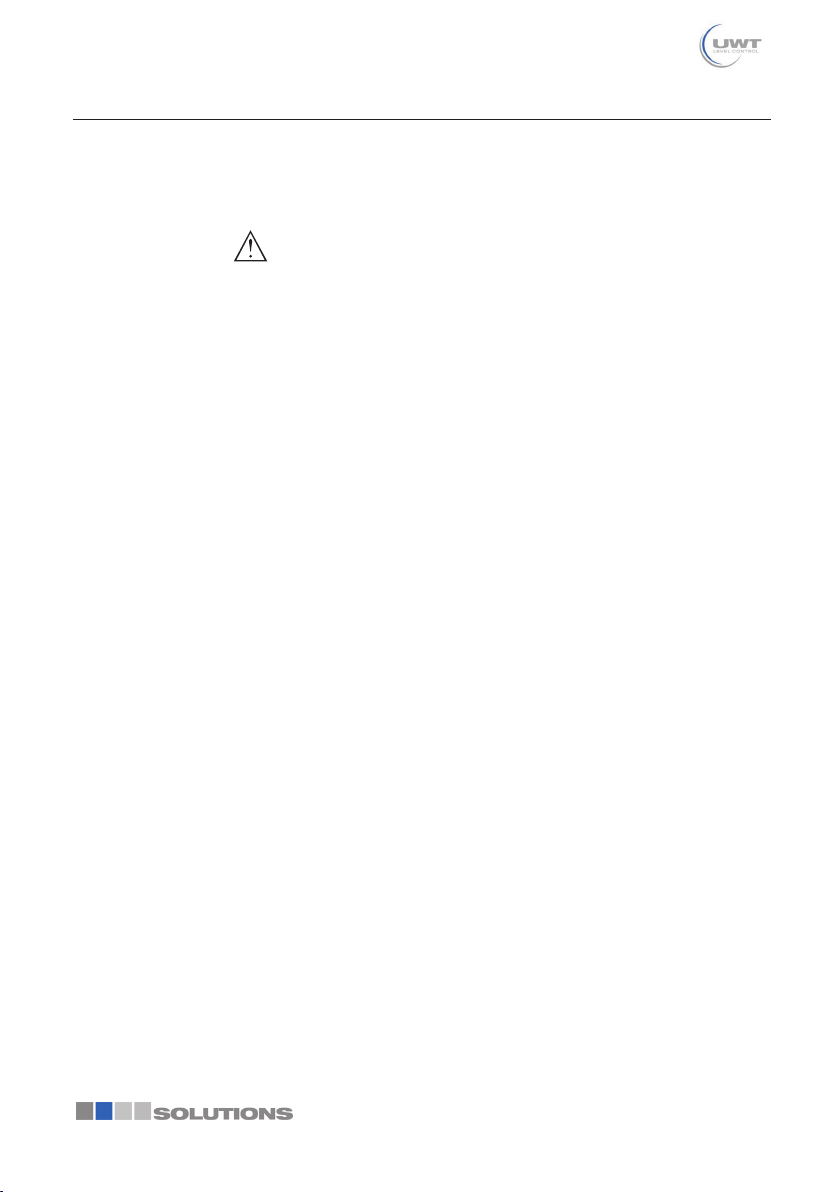
NivoRadar 7100 is a sensor for continuous level measurement.
You can nd detailed information about the area of application in
chapter " Product description".
Operational reliability is ensured only if the instrument is properly
used according to the specications in the operating instructions
manual as well as possible supplementary instructions.
Warning about incorrect use
Inappropriate or incorrect use of this product can give rise to
application-specic hazards, e.g. vessel overll through incorrect
mounting or adjustment. Damage to property and persons or envi-
ronmental contamination can result. Also, the protective character-
istics of the instrument can be impaired.
General safety instructions
This is a state-of-the-art instrument complying with all prevailing
regulations and directives. The instrument must only be oper-
ated in a technically awless and reliable condition. The operator
is responsible for the trouble-free operation of the instrument.
When measuring aggressive or corrosive media that can cause a
dangerous situation if the instrument malfunctions, the operator
has to implement suitable measures to make sure the instrument is
functioning properly.
The safety instructions in this operating instructions manual, the
national installation standards as well as the valid safety regulations
and accident prevention rules must be observed by the user.
For safety and warranty reasons, any invasive work on the device
beyond that described in the operating instructions manual may
be carried out only by personnel authorised by the manufacturer.
Arbitrary conversions or modications are explicitly forbidden. For
safety reasons, only the accessory specied by the manufacturer
must be used.
To avoid any danger, the safety approval markings and safety tips
on the device must also be observed.
The low transmitting power of the radar sensor is far below the
internationally approved limits. No health impairments are to be
expected with intended use. The band range of the measuring
frequency can be found in chapter " Technical data".

NivoRadar®Continuous level measurement
Series NR 7100
Technical information / Instruction manual
For your safety
page 4
Mode of operation - Radar signal
Country specic settings for the radar signals are determined via the
mode. The operating mode must be set in the operating menu via
the respective operating tool at the beginning of the setup.
Caution:
Operating the device without selecting the relevant mode consti-
tutes a violation of the regulations of the radio approvals of the
respective country.
Installation and operation in the USA and Canada
This information is only valid for USA and Canada. Hence the fol-
lowing text is only available in the English language.
Installations in the US shall comply with the relevant requirements of
the National Electrical Code (ANSI/NFPA70).
Installations in Canada shall comply with the relevant requirements
of the Canadian Electrical Code.

NivoRadar®Continuous level measurement
Series NR 7100
Technical information / Instruction manual
page 5
Product description
Conguration
The scope of delivery encompasses:
• Radar sensor
• Information sheet " Documents and software" with:
–Instrument serial number
–QR code with link for direct scanning
• Information sheet " PINs and Codes" (with Bluetooth versions)
with:
–Bluetooth access code
• Information sheet " Access protection" (with Bluetooth versions)
with:
–Bluetooth access code
–Emergency Bluetooth unlock code
–Emergency device code
The further scope of delivery encompasses:
• Documentation
–Ex-specic " Safety instructions" (with Ex versions)
–Radio licenses
–If necessary, further certicates
Note:
Optional instrument features are also described in this operating
instructions manual. The respective scope of delivery results from
the order specication.
This operating instructions manual applies to the following instru-
ment versions:
• Hardware version from 1.0.0
• Software version from 1.2.0
Scope of delivery
Scope of this operating
instructions

NivoRadar®Continuous level measurement
Series NR 7100
Technical information / Instruction manual
Product description
page 6
4
5
1
2
3
Fig. 1: Components of NivoRadar 7100
1 Radar antenna
2 Processtting
3 Process seal
4 Electronics housing
5 Ventilation/pressure compensation
The type label contains the most important data for identication
and use of the instrument.
UWT GmbH
D-87488 Betzigau
NivoRadar
Assembled in Germany
Technical Data
Article No.:
Serial No.:
1
6
5
4
3
2
Fig. 2: Layout of the type label (example)
1 Instrument type
2 Field for approvals
3 Order number
4 Technical data
5 Symbol for Bluetooth access
6 QR code for device documentation
Principle of operation
NivoRadar 7100 is a radar sensor for non-contact, continuous level
measurement. It is suitable for liquids and solids in practically all
industries.
Constituent parts
Type label
Application area

NivoRadar®Continuous level measurement
Series NR 7100
Technical information / Instruction manual
Product description
page 7
The instrument emits a continuous, frequency-modulated radar
signal through its antenna. The emitted signal is reected by the
medium and received by the antenna as an echo with modied
frequency. The frequency change is proportional to the distance and
is converted into the level.
Adjustment
Devices with integrated Bluetooth module can be adjusted wire-
lessly via smartphone/tablets (iOS or Android operating system).
12
Fig. 3: Wireless connection to standard operating devices with integrated
BluetoothLE
1 Sensor
2 Smartphone/Tablet
Packaging, transport and storage
Your instrument was protected by packaging during transport. Its
capacity to handle normal loads during transport is assured by a
test based on ISO4180.
The packaging consists of environment-friendly, recyclable card-
board. For special versions, PE foam or PE foil is also used. Dispose
of the packaging material via specialised recycling companies.
Transport must be carried out in due consideration of the notes on
the transport packaging. Nonobservance of these instructions can
cause damage to the device.
The delivery must be checked for completeness and possible transit
damage immediately at receipt. Ascertained transit damage or
concealed defects must be appropriately dealt with.
Up to the time of installation, the packages must be left closed and
stored according to the orientation and storage markings on the
outside.
Unless otherwise indicated, the packages must be stored only
under the following conditions:
• Not in the open
• Dry and dust free
• Not exposed to corrosive media
Functional principle
Wireless adjustment
Packaging
Transport
Transport inspection
Storage

NivoRadar®Continuous level measurement
Series NR 7100
Technical information / Instruction manual
Product description
page 8
• Protected against solar radiation
• Avoiding mechanical shock and vibration
• Storage and transport temperature see chapter " Supplement -
Technical data - Ambient conditions"
• Relative moisture 20…85%
Storage and transport
temperature

NivoRadar®Continuous level measurement
Series NR 7100
Technical information / Instruction manual
page 9
Technical data
Technical data
Note for approved instruments
The technical data in the respective safety instructions which are included in delivery are valid for
approved instruments (e.g. with Ex approval). These data can differ from the data listed herein,
for example regarding the process conditions or the voltage supply.
All approval documents can be downloaded from our homepage.
Materials and weights
Materials, wetted parts
ƲAntenna, process tting PVDF
ƲProcess seal 1) FKM, EPDM
Materials, non-wetted parts
ƲHousing Plastic PBT (Polyester)
ƲHousing seals O-rings (silicone)
ƲCable gland PA
ƲSealing, cable gland EPDM
ƲBlind plug, cable gland PA
Weight 0.7kg (1.543lbs)
Torques
Max. torque mounting boss 7Nm (5.163lbf ft)
Max. torque for NPT cable glands and
Conduit tubes
10Nm (7.376lbfft)
Input variable
Measured variable The measured variable is the distance between the
antenna edge of the sensor and the medium surface.
The antenna edge is also the reference plane for the
measurement.
1) G type threaded connections only, EPDM for devices with food/pharmaceutical certication

NivoRadar®Continuous level measurement
Series NR 7100
Technical information / Instruction manual
Technical data
page 10
2
1
Fig. 4: Data of the input variable
1 Reference plane
2 Measured variable, max. measuring range
Max. measuring range 1) 8m (26.25ft)
Recommended measuring range 2) up to 5m (16.4ft)
Min. dielectric constant of the medium 3) εr ≥1.6
blocking distance 4)
ƲModes 1, 2, 4 0mm (0in)
ƲMode 3 ≥250mm (9.843in)
Switch-on phase
Run-up time for UB = 12VDC, 18VDC,
24VDC
<15s
Starting current for run-up time ≤3.6mA
20 mA
≤ 3,6 mA
4 mA
t
2 3 4
1
Fig. 5: Run-up time and measured value output
1 UBOn
2 Run-up time
3 Measured value output
4 UBOff
1) Depending on application and medium
2) With bulk solids
3) Depending on application and medium
4) Depending on the operating conditions

NivoRadar®Continuous level measurement
Series NR 7100
Technical information / Instruction manual
Technical data
page 11
Power consumption
Sensor current
Operating voltage
12VDC 18VDC 24VDC
≤3.6mA <45mW <65mW <90mW
4mA <50mW <75mW <100mW
20mA <245mW <370mW <485mW
Output variable
Output signal 4…20mA
Range of the output signal 3.8…20.5mA (default setting)
Signal resolution 0.3µA
Resolution, digital 1mm (0.039in)
Fault signal, current output (adjustable) ≤3.6mA, >=21mA, last valid measured value
Max. output current 22mA
Load See load resistance under Power supply
Starting current ≤3.6mA; ≤10mA for 5ms after switching on
Damping (63% of the input variable),
adjustable
0…999s
Deviation(accordingtoDINEN60770-1)
Process reference conditions according to DIN EN61298-1
ƲTemperature +18…+30°C (+64…+86°F)
ƲRelative humidity 45…75%
ƲAir pressure 860…1060mbar/86…106kPa (12.5…15.4psig)
Installation reference conditions
ƲDistance to installations >200mm (7.874in)
ƲReector Flat plate reector
ƲFalse reections Biggest false signal, 20dB smaller than the useful
signal
Deviation with liquids ≤5mm (meas. distance >0.25m/0.8202ft)
Non-repeatability 1) ≤5mm
Deviation with bulk solids The values depend to a great extent on the application.
Binding specications are thus not possible.
1) Already included in the meas. deviation

NivoRadar®Continuous level measurement
Series NR 7100
Technical information / Instruction manual
Technical data
page 12
0,25 m (0.8202 ft)
10 mm (0.3937 in)
- 10 mm (- 0.3937 in)
5 mm (0.1969 in)
- 5 mm (- 0.1969 in)
0
12
Fig. 6: Deviation under reference conditions 1)
1 Antenna edge, reference plane
2 Recommended measuring range
Variablesinuencingmeasurementaccuracy2)
Specicationsapplytothedigitalmeasuredvalue
Temperature drift - Digital value <3mm/10K, max.5mm
Specicationsapplyalsotothecurrentoutput
Temperature drift - Current output <0.03%/10K or max. 0.3% relating to the 16.7mA
span
Deviation in the current output due to
digital/analogue conversion
<15µA
Additional measurement deviation through electromagnetic interference
ƲAccording to NAMUR NE21 <80µA
ƲAccording to EN61326-1 None
ƲAccording to IACSE10 (shipbuilding)/
IEC60945
<250µA
Characteristics and performance data
Measuring frequency W-band (80GHz technology)
Measuring cycle time 3) ≤250ms
Step response time 4) ≤3s
Beam angle 5) 8°
Emitted HF power (depending on the parameter setting) 6)
ƲAverage spectral transmission power
density
-3dBm/MHz EIRP
1) In case of deviations from reference conditions, the offset due to installation can be up to ±4mm. This offset
can be compensated by the adjustment.
2) Determination of the temperature drift acc. to the limit point method
3) With operating voltage UB ≥24VDC
4) Time span after a sudden distance change from 1m to 5m until the output signal reaches 90% of the nal
value for the rst time (IEC61298-2). Valid with operating voltage UB ≥24VDC.
5) Outside the specied beam angle, the energy level of the radar signal is 50% (-3dB) less.
6) EIRP: Equivalent Isotropic Radiated Power

NivoRadar®Continuous level measurement
Series NR 7100
Technical information / Instruction manual
Technical data
page 13
ƲMax. spectral transmission power
density
+34dBm/50MHz EIRP
ƲMax. power density at a distance of
1m
<3µW/cm²
Ambient conditions
Ambient temperature -40…+60°C (-40…+140°F)
Storage and transport temperature -40…+80°C (-40…+176°F)
Mechanical environmental conditions
Vibrations (oscillations) Class 4M8 acc. to IEC60271-3-4 (5g at 4…200Hz)
Impacts (mechanical shock) Class 6M4 acc. to IEC60271-3-6 (50g, 2.3ms)
Impact resistance IK07 acc. to IEC62262
Process conditions
For the process conditions, please also note the specications on the type label. The lowest
value (amount) always applies.
Process temperature -40…+60°C (-40…+140°F)
Process pressure -1…3bar (-100…200kPa/-14.5…43.51psig)
Electromechanical data
Cable entry
ƲOptions M20x1.5; ½NPT
ƲCable gland M20x1.5 (cable diameter 5…9mm)
ƲClosing cap ½NPT
Wire cross-section (spring-loaded terminals)
ƲMassive wire, stranded wire 0.2mm² (AWG24)…2.5mm² (AWG14)
ƲStranded wire with end sleeve 0.2mm² (AWG24)…1.5mm² (AWG16)
Bluetooth interface
Bluetooth standard Bluetooth 5.0
Frequency 2.402…2.480GHz
Max. emitted power +2.2dBm
Max. number of participants 1
Effective range typ. 1) 25m (82ft)
Adjustment
Smartphone/Tablet Adjustment app
1) Depending on the local conditions

NivoRadar®Continuous level measurement
Series NR 7100
Technical information / Instruction manual
Technical data
page 14
Voltagesupply
Operating voltage UB
Ʋat 4mA 12…35VDC
Ʋat 20mA 9…35VDC
Reverse voltage protection Integrated
Permissible residual ripple
Ʋfor 12V<UB<18V ≤0.7Veff (16…400Hz)
Ʋfor 18V<UB<35V ≤1Veff (16…400Hz)
Load resistor
ƲCalculation (UB - Umin)/0.022A
ƲExample - with UB=24VDC (24V - 12V)/0.022A=545Ω
Overvoltage protection
Dielectric strength against metallic
mounting parts
>10kV
Overvoltage resistance (test impulse
voltages 1.2/50µs at 42Ω)
>1000V
Additional overvoltage arrester Due to the oating structure of the electronics and
comprehensive insulation measures generally not
necessary.
Electrical protective measures
Potential separation Electronics potential free up to 500VAC
Protection rating IP66/IP67 acc. to IEC60529
Type4X acc. to UL50
Altitude above sea level 5000m (16404ft)
Protection class III
Pollution degree 4

NivoRadar®Continuous level measurement
Series NR 7100
Technical information / Instruction manual
Technical data
page 15
Dimensions
50 mm
(1.97")
40,5 mm
(1.59")
105 mm
(4.13")
25 mm
(0.98")
G1½
SW 50
ø 58 mm
(2.28")
ø 71 mm
(3.05")
4,5 mm
(0.18")
ø 80 mm
(3.15")
1½ NPT R 1½
145 mm
(5.71")
1 2 3
Fig. 7: Dimensions NivoRadar 7100
1 Thread G1½
2 Thread1½NPT
3 Thread R1½

NivoRadar®Continuous level measurement
Series NR 7100
Technical information / Instruction manual
page 16
Mounting
General instructions
The instrument is suitable for standard and extended ambient
conditions acc. to DIN/EN/IEC/ANSI/ISA/UL/CSA61010-1. It can be
used indoors as well as outdoors.
Note:
For safety reasons, the instrument must only be operated within
the permissible process conditions. You can nd detailed informa-
tion on the process conditions in chapter " Technical data" of the
operating instructions or on the type label.
Hence make sure before mounting that all parts of the instrument
exposed to the process are suitable for the existing process condi-
tions.
These are mainly:
• Active measuring component
• Process tting
• Process seal
Process conditions in particular are:
• Process pressure
• Process temperature
• Chemical properties of the medium
• Abrasion and mechanical inuences
Protect your instrument against moisture ingress through the follow-
ing measures:
• Use a suitable connection cable (see chapter " Connecting to
power supply")
• Tighten the cable gland or plug connector
• Lead the connection cable downward in front of the cable entry
or plug connector
This applies mainly to outdoor installations, in areas where high hu-
midity is expected (e.g. through cleaning processes) and on cooled
or heated vessels.
Note:
Make sure that during installation or maintenance no moisture or
dirt can get inside the instrument.
To maintain the housing protection, make sure that the housing lid is
closed during operation and locked, if necessary.
Mounting instructions
Radar sensors for level measurement emit electromagnetic waves.
The polarization is the direction of the electrical component of these
waves.
The polarization direction is marked on the housing, see following
drawing:
Ambient conditions
Process conditions
Protection against mois-
ture
Polarisation

NivoRadar®Continuous level measurement
Series NR 7100
Technical information / Instruction manual
Mounting
page 17
1
Fig. 8: Position of the polarisation
1 Marking of the polarisation
Note:
When the housing is rotated, the direction of polarization changes
and hence the inuence of the false echo on the measured value.
Please keep this in mind when mounting or making changes later.
When mounting the device, keep a distance of at least 200mm
(7.874in) from the vessel wall. If the device is installed in the center
of dished or round vessel tops, multiple echoes can arise. However,
these can be suppressed by an appropriate adjustment (see chapter
" Set up").
If you cannot maintain this distance, you should carry out a false
signal suppression during setup. This applies particularly if buildup
on the vessel wall is expected. In such cases, we recommend
repeating the false signal suppression at a later date with existing
buildup.
> 200 mm
(7.87
")
Fig. 9: Mounting of the radar sensor on round vessel tops
In vessels with conical bottom it can be advantageous to mount the
device in the centre of the vessel, as measurement is then possible
down to the bottom.
Installation position

NivoRadar®Continuous level measurement
Series NR 7100
Technical information / Instruction manual
Mounting
page 18
Fig. 10: Mounting of the radar sensor on vessels with conical bottom
The centre of the antenna lens is the beginning of the measuring
range and at the same time the reference plane for the min./max.
adjustment, see following diagram:
1
Fig. 11: Reference plane
1 Reference plane
Do not mount the instruments in or above the lling stream. Make
sure that you detect the medium surface, not the inowing product.
Fig.12:Mountingoftheradarsensorwithinowingmedium
Reference plane
Inowingmedium

NivoRadar®Continuous level measurement
Series NR 7100
Technical information / Instruction manual
Mounting
page 19
With threaded connection, the antenna end should protrude at least
5mm (0.2in) out of the nozzle.
ca. 5 mm
Fig. 13: Thread mounting
If the reective properties of the medium are good, you can mount
NivoRadar 7100 on sockets longer than the antenna. The socket
end should be smooth and burr-free, if possible also rounded.
You will nd recommended values for socket heights in the following
illustration or the table. The values come from typical applications.
Deviating from the proposed dimensions, also longer sockets are
possible, however the local conditions must be taken into account.
d
h
Fig. 14: Socket mounting
Socket diameter d Socket length h
40mm 1½" ≤150mm ≤5.9in
50mm 2" ≤200mm ≤7.9in
80mm 3" ≤300mm ≤11.8in
100mm 4" ≤400mm ≤15.8in
150mm 6" ≤600mm ≤23.6in
Note:
When mounting on longer nozzles, we recommend carrying out a
false signal suppression (see chapter " Parameter adjustment").
The mounting location of the radar sensor should be a place where
no other equipment or xtures cross the path of the radar signals.
Vessel installations, such as e.g. ladders, limit switches, heating
spirals, struts, etc., can cause false echoes and impair the useful
echo. Make sure when planning your measuring point that the radar
sensor has a " clear view" to the measured product.
In case of existing vessel installations, a false signal suppression
should be carried out during setup.
If large vessel installations such as struts or supports cause false
echoes, these can be attenuated through supplementary measures.
Threaded socket und
socket piece
Vesselinstallations

NivoRadar®Continuous level measurement
Series NR 7100
Technical information / Instruction manual
Mounting
page 20
Small, inclined sheet metal bafes above the installations " scatter"
the radar signals and prevent direct interfering reections.
Fig.15:Coverat,large-areaproleswithdeectors
In liquids, direct the device as perpendicular as possible to the
medium surface to achieve optimum measurement results.
Fig. 16: Alignment in liquids
If there are agitators in the vessel, a false signal suppression should
be carried out with the agitators in motion. This ensures that the
interfering reections from the agitators are saved with the blades in
different positions.
Fig. 17: Agitators
Through the action of lling, stirring and other processes in the ves-
sel, compact foams which considerably damp the emitted signals
may form on the medium surface.
Orientation
Agitators
Foam generation
Other manuals for NivoRadar NR 7100 Series
1
Table of contents
Other UWT Measuring Instrument manuals

UWT
UWT NivoGuide 3100 User manual

UWT
UWT Rotonivo RN 3000 User manual

UWT
UWT NivoRadar NR 7000 Series User manual

UWT
UWT Nivotec NT 4500 User manual

UWT
UWT Nivobob NB 3000 User manual

UWT
UWT NivoRadar NR 7200 Series User manual

UWT
UWT Nivobob NB 4000 User manual

UWT
UWT Nivotec NT 4600 User manual

UWT
UWT NivoRadar NR 4100 Series User manual

UWT
UWT NG 8100 User manual