CESVA SC250 User manual

SC250
Sound level meter
Spectrum Analyser
USER’S MANUAL
M_SC250_v0005_20211103_EN


1
founded in 1969 in Barcelona, has always engaged in the
manufacturing of sound equipment and instruments with in-house R&D&I and
patents.
We belong to national and international committees for the establishment and
revision of standards and regulations.
has a fast and efficient distribution network in over 40 countries
around the world.
We offer our customers an after-sales service to ensure the long life of our
instruments. Periodic tests and calibration services are also available.
Our website is the focal point for finding information on our products, requesting
no-obligation quotes, downloading software, contacting us and being kept
updated about all the training events and exhibitions we are present at on a
regular basis.
Taking care of and listening to our customers brings us closer to them and allows
us to provide them with a measuring solution that is totally adapted to their
needs.
The Bluetoothtrademark is owned by Bluetooth SIG, Inc.

2 Contents
1. What does this manual cover? 6
2. Equipment and literature 7
3. General device description 8
3.1 SC250 sound level meter and spectrum analyser 8
3.2 Main features of the SC250 8
3.3 Device parts 10
4. Inputs and outputs 12
4.1 Communication inputs/outputs 12
4.2 AC output 12
5. Keypad 13
6. Screen 15
6.1 Areas of the screen 15
6.1.1 Indicator area 15
6.1.2 Work area 17
6.1.3 Screen area 17
6.1.4 Time area 17
6.1.5 Available actions area 18
6.2 Turn off the screen 18
7. Power 19
7.1 Types of power 19
7.1.1 Battery power 19
7.1.2 Power by USB 20
7.2 Energy saving 20
8. Assembling and dismantling the device 21
8.1 Windscreen 21
8.2 Extension cable 22
8.2.1 Removing and connecting the preamplifier 22
8.2.2 Connecting the extension cable 23
8.3 Outdoor kit 24
9. Switching the device on and off 25
9.1 Turn on the device 25
Contents

Contents 3
9.1.1 SC250 Initial Self Test 26
9.1.2 Check the firmware version of the SC250 27
9.2 Turn off the device 27
10. Check the device 28
10.1 Checking the SC250 28
11. Measuring and recording 30
11.1 Prior steps 31
11.2 Measuring 31
11.3 Make a recording 32
11.4 Overload indicator 32
11.5 "Under range" indicator 33
12. Menu 34
12.1 Access the menu 34
12.2 Areas of the menu 35
12.3 Move through the menu 35
13. Screens 36
13.1 Change screen 36
13.2 Actions in the display 37
13.3 Screens 37
14. Supplementary options 43
14.1 Zoom 43
14.2 Backerase 44
15. Settings and adjustments 45
15.1 Menu options 45
15.1.1 REGISTERS option 46
15.1.2 MEMORY option 47
15.1.3 USB option 48
15.1.4 BLUETOOTH®option 49
15.1.5 WIFI option 49
15.1.6 TIMES option 50
15.1.7 CSV option 51
15.1.8 DATE AND TIME option 51
15.1.9 MICROPHONE SETTINGS option 53
15.1.10 POWER option 54
15.1.11 BRIGHTNESS option 54
15.1.12 CLOUD option 55
15.1.13 Option INFORMATION 55
16. Registers and memory management 56
16.1 Save a final result 56
16.2 Make a recording 57
16.3 Structure of a register 59
16.4 View and delete registers 59

4 Contents
16.5 Erase the memory 59
17. Use of the inputs and outputs 60
17.1 AC output 60
17.2 Digital inputs and outputs 61
17.2.1 USB communication 61
17.2.2 Bluetooth ®communication. 63
17.2.3 WIFI 63
18. Accessories 64
18.1 Accessories supplied 64
18.2 Optional accessories 64
19. Technical specifications 66
19.1 REFERENCE CONDITIONS 66
19.2 MICROPHONES AND PREAMPLIFIERS 67
19.2.1 Microphone models and their main features 67
19.2.2 Sound field correction for periodic tests 67
19.2.3 Frequency response 68
19.2.4 Effect of the optional accessories on the microphone 79
19.2.5 Directional response 80
19.2.6 Directivity indexes 86
19.2.7 Preamplifier connector 89
19.3 MEASUREMENT 89
19.3.1 Warm-up time 89
19.3.2 Measurement range 89
19.3.3 Linearity range 90
19.3.4 Noise 91
19.3.5 Time and clock performance 91
19.3.6 Frequency weighting 92
19.4 CALIBRATION 93
19.5 OCTAVE AND THIRD OCTAVE BAND FILTERS 93
19.5.1 Octave and third octave band filters 93
19.5.2 Measurement range (octave band spectrum analyser)95
19.5.3 Measurement range (third octave band spectrum
analyser) 95
19.6 ENVIRONMENTAL, ELECTROSTATIC AND RADIO
FREQUENCY CRITERIA 96
19.6.1 Stabilisation time 96
19.6.2 Environmental criteria 96
19.6.3 Electrostatic criteria 97
19.6.4 Criteria of the fields at the frequency of the mains
supply and radio frequency fields. 97
19.7 INPUTS AND OUTPUTS 99
19.7.1 AC output 99
19.7.2 USB communication 99
19.7.3 Wireless communication 99

Contents 5
19.8 SCREEN 100
19.9 POWER 100
19.9.1 Batteries 100
19.9.2 External power 101
19.10 DIMENSIONS AND WEIGHT 101
19.11 STANDARDS 101
19.11.1 Standards 101
19.11.2 Certificates 102
19.11.3 Notes 102
20. Maintenance and precautions 103
21. Tips for taking measurements 105
22. Firmware update and module activation 106
22.1 Firmware update 106
22.2 Activation of an optional module of the SC250 107
22.3 Activating an optional SC250 Link module 108
23. Functions 109
23.1 Nomenclature of functions 109
23.1.1 Sound level meter parameters 109
23.1.2 1/1 octave band parameters 111
23.1.3 1/3 third octave band parameters 112
23.2 Description of functions 113
23.2.1 Sound pressure level with Fast and Slow time
weighting 113
23.2.2 Sound pressure level with Impulse time weighting 114
23.2.3 Peak sound pressure level 114
23.2.4 Equivalent continuous sound pressure level 114
23.2.5 Taktmaximal-Mittelungspegel 115
23.2.6 Percentiles 116
24. Reference to standards 117
24.1 Standard UNE-EN 61672-1:2014 117
24.2 Standard UNE-EN 61260-1:2014 126

6 Chapter 1 What does this manual cover?
This manual provides you with all the information you need to make the most of
your new device.
The information is divided into 7 sections:
A first section that brings together the chapters with the main characteristics of
the device and its physical parts (chapters 3, 4, 5, 6, 7 and 8).
The second shows the operation of the device to be able to carry out the
measurements (chapters 9, 10, 11, 12, 13 and 14).
The third section focuses on the configuration of the device: menu options and
procedures for making the various settings (chapters 15 and 16).
The fourth section develops other important topics such as the connection to the
PC and accessories (chapters 17 and 18).
The fifth section contains the technical specification of the SC250 sound level
meter to know in detail the device you are working with (chapter 19).
And finally, the sixth section includes several chapters that collect information
such as: maintenance and precautions, tips for taking measurements,
nomenclature and description of functions, etc. (chapters 20, 21, 22, 23 and 24).
What does this manual cover?
1. What does this manual cover?
1
NOTE: If you already know the device and only want to consult the
information to carry out measurements, see chapters 9, 10, 11, 12, 13 and 14.

Chapter 2 Equipment and literature 7
The first step is to check that all the equipment and literature supplied with the
device is there:
Material included:
SC250 sound level meter
FN004 case
PV009 windscreen
3 x 1.5 volt alkaline batteries, AA (LR6) size
USB connection cable - USB type C CN500
Literature included:
Quick start guide
Warranty
If any of these items are missing, please contact your official
distrubutor.
Equipment and literature
2. Equipment and literature
2

8 Chapter 3 General device description
This chapter provides an overview of the SC250 sound level meter. It describes
its main characteristics and identifies its different parts.
3.1 SC250 sound level meter and spectrum analyser
The SC250 perfectly combines versatility with ease of use.
Thanks to its touch screen and its menu, the operation of this device is extremely
fast, simple and intuitive.
In addition, the device measures all the parameters simultaneously with the
different time bases, frequency and temporal weightings.
The SC250 is a sound level meter that complies with the specifications of the
international standard IEC 61672 for class 1, and the American standards ANSI
S1.4 and ANSI S1.43 for type 1, both for the response to incident sound waves
on the microphone in the reference direction in a free field and for the response
to waves with random incidence in a diffuse field.
The SC250 can be upgraded with the FR250 module. It activates the spectral
analysis in octave band (1/1) and third octave band (1/3).
The SC250 has advanced features, such as the management of the sound level
meter from a mobile phone or the Tablet through the SC250 Link App, or
uploading the measurements made to the CESVACloud server, so that they are
available from anywhere.
3.2 Main features of the SC250
The SC250 includes the following main features:
COLOUR TOUCHSCREEN:
The SC250 has a colour touchscreen for performing all the device's
operations.
The 3.5" screen, with a resolution of 320x240 , is conducive to any action that
you want to perform being very fast and intuitive, since everything is done
through the touchscreen.
The sound level meter has only one key, to turn it on.
General device description
3. General device description
3

Chapter 3 General device description 9
The screen of the SC250 provides a clear, sharp view in broad daylight; it also
lights up automatically when the equipment turns on, allowing you to work
even in low-light environments.
PHILOSOPHY:
The SC250 maintains the philosophy of the instruments:
versatility, simplicity and easy handling.
No scales: there is no need to configure the measurement range of the SC250
according to the dynamic range of the sound event to be measured.
The SC250 measures all functions simultaneously, with different time and
frequency weightings (A, C and Z) and with different time bases (t, T, 1 s, 20
ms*), as well as global and spectral parameters.
* 20 ms optional (see 15.1.7)
MEMORY:
The SC250 has internal memory to store the recordings and final results. As
well as date and time change logs, sensitivity settings and firmware version
(see 16).
BACKERASE:
With the BACKERASE option, the SC250 can erase the last 10 seconds of the
current measurement. This option is perfect when unwanted sound events
appear during measurement (see 14.2).
ZOOM:
The automatic ZOOM option allows you to view very stable sound events in
more detail (see 14.1).
ICON MENU:
The device is configured through a menu composed only of easily identifiable
and recognisable icons and without the need to configure languages.
COMMUNICATIONS:
The SC250 can communicate with a PC through the USB Type-C port (see
17.2.1), or through Bluetooth® communication (see 17.2.2). It is also possible
to communicate via WIFI (see 17.2.3).
The SC250 can also be handled using the SC250 Link app via
Bluetooth®.
The Bluetooth®trademark is owned by Bluetooth SIG, Inc.
SC250 Link App available for download from the Google Play platform

10 Chapter 3 General device description
3.3 Device parts
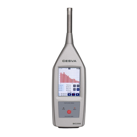
The following figure describes the most important parts of the SC250:
1. Precision ½'' condenser microphone·The SC250 works with the C140
microphone.
2. Preamplifier · The preamplifier of the SC250 is removable. It is connected
through the LEMO connector (3).
3. LEMO connector of the preamplifier · Male LEMO connector of the
preamplifier. This is protected by the protective cone.
4. LEMO connector of the sound level meter· Female LEMO connector of the
SC250 sound level meter. This is protected by the protective cone.
5. Protective cone· Conical piece that covers the female LEMO connectors of
the sound level meter and male of the preamplifier to protect them.
6. Screen· 3.5” backlit colour touch screen.
7. Membrane keypad· Extra-thin keypad minimises reflections.
8. Manufacturer's information· Area where the brand and origin of design and
manufacture are indicated.
9. UNE-EN Marking·In this area the model and serial number of the sound level
meter are detailed, as well as the UNE-EN standards that it complies with.
(The IEC and ANSI standards it complies with are specified in the information
screen (see 15.1.13))
10. Class information ·This area details the class with which the sound level
meter meets the standards specified in the UNE-EN, IEC and ANSI marking,
depending on the microphone.
11. Tripod support ·Recessed tripod support with standard ¼’’ W thread. (TR040
and TR050).
12. RAEE Marking · Indicates the separate collection of electrical/electronic
equipment.
13. CE Marking · European conformity mark.
14. Battery cover · Battery protection cover, it should only be removed to change
them. This is held in place by a screw. The symbol is shown on the cover
(see 19.9.1).
15. Protective cover for the connectors · Cover to protect the connectors from
possible damages.
16. USB type C connector · USB C connector for power and digital
communication.
17. AC output · Direct output from the preamplifier without frequency weighting.
Notable among its utilities is the audio recordings.

Chapter 3 General device description 11
12 Chapter 4 Inputs and outputs
This chapter lists the inputs and outputs of the SC250. It indicates how to identify
them and how to extract data from them.
The inputs and outputs of the SC250 are on the bottom of the device, protected
by a removable protective cover. To access them, remove the cover. Remember
to put it back once the operation is finished.
The SC250 has the following inputs and outputs:
4.1 Communication inputs/outputs
1. USB C [16] Bidirectional input/output for communication with a PC and to power
the device (see 17.2.1). To connect the SC250 to a PC through this input use
the CN500 cable.
2. Bluetooth®communication. Wireless input/output for two-way digital
communication with a PC or with a device (tablet, mobile, ...) via radio
frequency (see 17.2.2).
3. WIFI Connection to a wireless WIFI network to access the CESVACloud server
(see 17.2.3).
4.2 AC output
The AC output [17]contains an AC signal proportional to the output of the
preamplifier (see 17.1). This allows:
Listen to the sound event being measured and determine if it is influenced by
noises other than those to be measured.
To record this signal on a recording device for recognition of the sound event
being measured.
Inputs and outputs
4. Inputs and outputs
4

Chapter 5 Keypad 13
This chapter describes the elements that comprise the keypad.
The SC250 has a touchscreen, so that the keypad area contains only one key
and two LEDs.
KEY
FUNCTION
ON/OFF
Key to turn the SC250 on and off. And the screen.
To turn on the device, keep the key pressed down for a few seconds.
To turn off the device, press the key for a few seconds. The sound level
meter cannot be turned off while a measurement or recording is in
progress.
When the device is on, to turn off the screen, press the key once. Then
to turn it on, press the key again.
LED
FUNCTION
POWER
LED that indicates if the device and the screen are on or off.
The POWER LED has 3 operating modes:
POWER OFF:
The device is off
The device is on and the screen is also on.
Keypad
5. Keypad
5

14 Chapter 5 Keypad
POWER ON:
The device is on and the screen is off (sleep)
INTERMITTENT POWER:
The device is on and the batteries are running low.
STATUS
LED indicating the status of the measurement.
The STATUS LED has 3 operating modes when the device is on:
STATUS OFF:
The measurement is stopped ( )
STATUS ON:
The measurement is paused ( )
INTERMITTENT STATUS:
The device is measuring ( ) or recording ( ).
In summary:
SC250
Screen
Measurement
LEDPOWER
LED STATUS
Off
Off
-
OFF
OFF
On
On
STOP
OFF
OFF
PAUSE
OFF
ON
PLAY / REC
OFF
ON (INTERMITTENT)
Off
STOP
ON
OFF
PAUSE
ON
ON
PLAY / REC
ON
ON (INTERMITTENT)
The battery is running low
-
ON (INTERMITTENT)
-

Chapter 6 Screen 15
This chapter defines the characteristics of the screen and details the information
it displays.
The SC250 has a 3.5” backlit colour touchscreen that allows immediate access
to any type of screen or menu on the device. The data are presented both
numerically and graphically.
The SC250 screen is divided into 5 areas.
6.1 Areas of the screen
6.1.1 Indicator area
The information that appears on it varies depending on whether it is a
measurement, a recording, the configuration of the SC250 or the measurement
status.
Screen
6. Screen
6

16 Chapter 6 Screen
TIME:
Shows the current time of the SC250 (hh:mm:ss).
FILE:
INDICATION
SITUATION
The final results are saved (see 16.1)
A recording is made (see 16.2)
A measurement that is stored in memory is displayed (see 16.4)
There is no measurement on the screen
A measurement is made (see 11.2)
FILTER:
Indicates the correction (filter) applied to the measurement. There are three
options available.
INDICATION
SITUATION
F
Free field correction
D
Diffuse field correction
TK200
Outdoor kit correction TK200
To change the filter (see 15.1.9).
DROPDOWN MENU ( ):
Shows all available menu options (see 15.1).
INDICATORS:
INDICATION
INFORMATION
Sound level meter configured as a mass storage device (see 15.1.3)
WIFI wireless communication activated (see 15.1.5)

Chapter 6 Screen 17
Bluetooth®communication activated (see 15.1.4)
Power by USB (see 7.1.2)
STATUS:
Shows the measurement status of the SC250.
INDICATION
SITUATION
Stopped
Measurement in progress
Recording in progress
Measurement temporarily stopped (Pause)
Recording temporarily stopped (Pause)
6.1.2 Work area
This area shows the value for the functions during the process of measurement,
recording or display of records (see 13).
6.1.3 Screen area
The SC250 has different screens for displaying the data (see 13).
This area indicates which screen is being displayed (SLM, 1/1 or 1/3).
To change the screen that is displayed (see 13.1).
6.1.4 Time area
This area is visible during a measurement, recording, or while viewing a register.
The time area shows the following information:
The elapsed integration time T
The elapsed measurement time t

18 Chapter 6 Screen
6.1.5 Available actions area
This area shows the available actions corresponding to the measurement.
ICON
FUNCTION
PLAY
Key to start a measurement or resume after a pause.
STOP
Key for stopping a measurement.
PAUSE
Key to temporarily stop a measurement/recording (pause).
BACKERASE
Key to erase backwards (Backerase) the last 10 seconds.
REC
Key to start a recording or resume after a pause.
SAVE
Key to save the final result in memory (It does not save the time history
of the measurement).
6.2 Turn off the screen
Turning off the device's screen while it is running saves energy. To turn off the
screen without turning off the device, press momentarily. The screen will
automatically turn off and the LED will turn on in power ON mode (see 5).
NOTE If the SC250 is to be left to measure for a long period of time, a image
persistence effect may occur, to avoid this possible consequence it is
recommended to turn off the screen. In any case, it should be remembered that
this effect is reversible and disappears the moment the screen is turned off.
Other manuals for SC250
2
Table of contents
Other CESVA Measuring Instrument manuals