Replace fuse/lamp only with the same type.
In the event of serious operating problem, stop using the unit immediately.
Never turn on and off the unit time after time.
The housing, the lenses, or the ultraviolet filter must be replaced if they are
visibly damaged.
DO NOT attempt to operate this unit if it becomes damaged. DO NOT attempt
any repairs
yourself. Repairs carried out by unskilled people can lead to damage or
malfunction. Please contact the nearest authorized technical assistance center
if needed.
Disconnect this product from its power source before servicing.
DO use the original packaging if the device is to be transported.
Avoid direct eye exposure to the light source while the product is on.
Never touch bulb with bare fingers, as it is very hot after using.
DO NOT operate this product if you see damage on the housing, shields, or
cables. Have the damaged parts replaced by an authorized technician at once
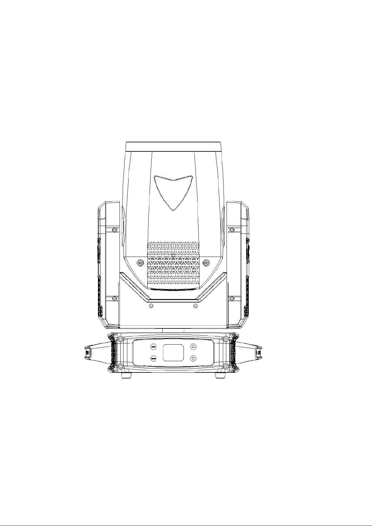
Installation:
The fixture should be fixed on the clamp. Always ensure that the unit is firmly
fixed to avoid vibration and slipping off during operation. Ensure that the
trussing or area of installation must be able to hold 10 times the weight without
any deformation. Always install a safety cable that can hold at least 12 times
the weight of the fixture when installing.DO install and operate by qualified
operator. It must be installed in a place where there is out of the reach of
people.
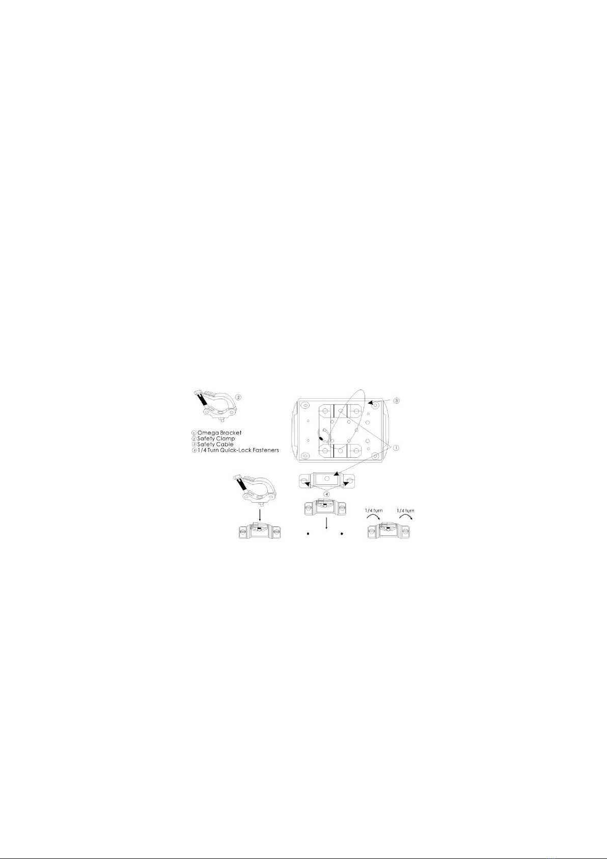
2.INSTALLATIONS
installations Note: In order to increase protection, please install the lamp on
the sidewalk, outside the seating area, or an area where unauthorized persons
may touch the lamp
Before installing the fixture on any surface, make sure that the installation area
can bear the minimum point load above 10 points of the weight of the
equipment. The installation of the fixing device must always be fixed with
auxiliary safety accessories (such as a suitable safety rope)
Do not stand directly under the equipment when installing, removing, or
servicing fixtures
From the ceiling or set on a flat surface (see the picture below). Ensure that
this fixture is kept at least 0.5m (1.5 feet) away from any flammable materials
(decorations, etc.)
Be sure to use and install the supplied safety rope to ensure safety and