8.Product parameter introduction
Input voltage: AC100-240V 50-60HZ
Output Voltage: V1:36V(Master board+LED driver), V2:12V(cooling fan+Display)
Power supply: 250W
Light source: 198W module high output white light LED
Light strip: 30pcs 0.5W RGB5050LED
Service life: 50,000 hours service life, low power consumption
Color temperature: 7500K
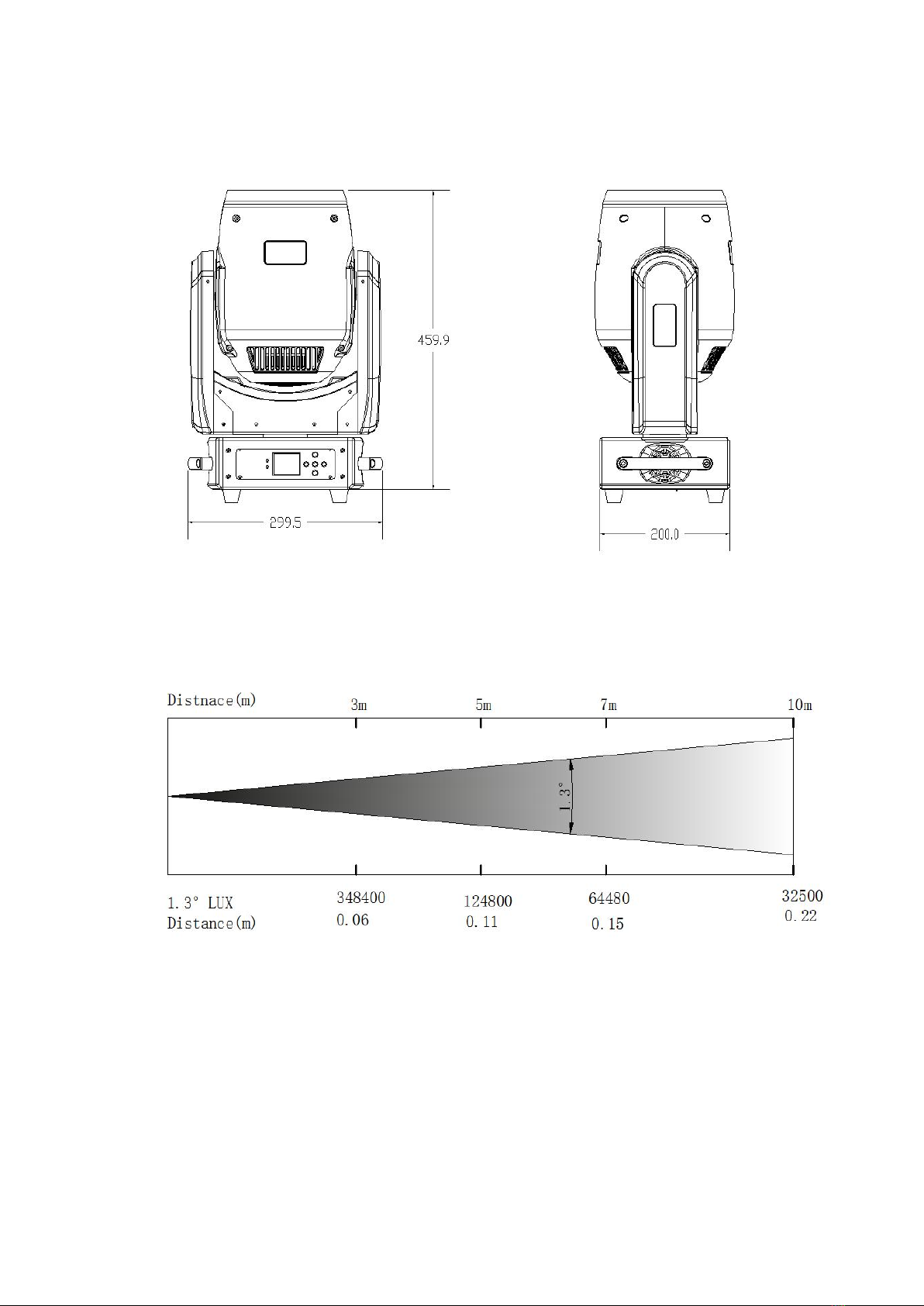
Beam angle: 1.3° beam angle, focusing function
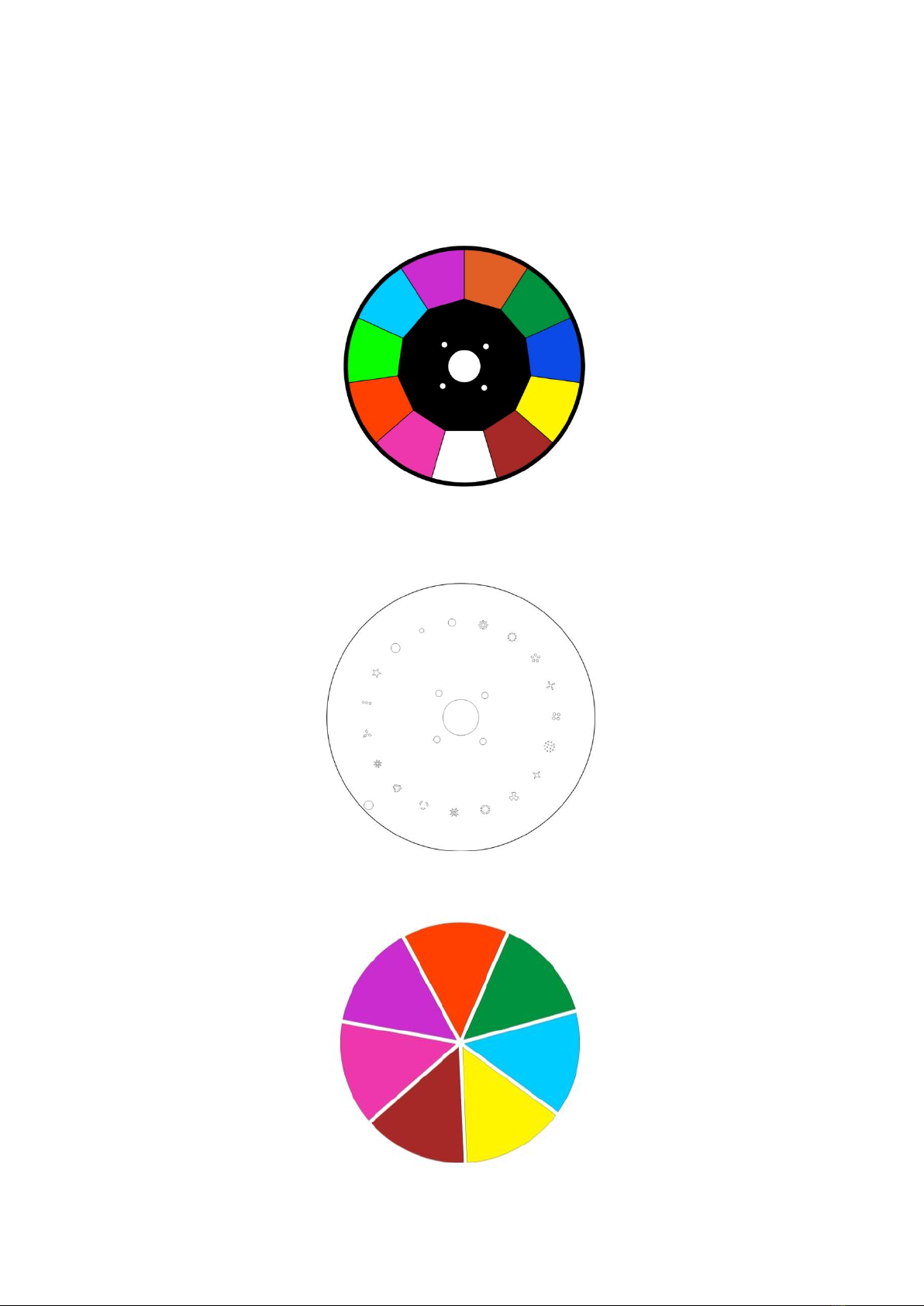
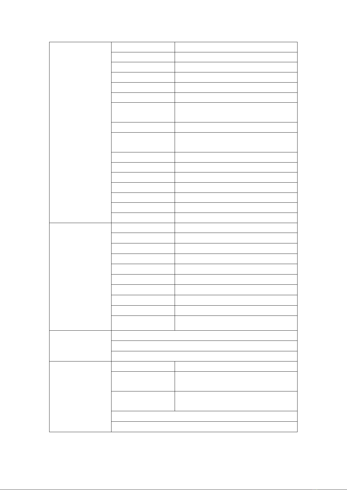
Color: 10 colors + white, variable direction and speed
Fixed gobos: 18 fixed gobos + white light, rotation and jitter
Prism: 16 prism, variable speed bidirectional rotation
With fog and colorful function
Strobe: high-speed strobe effect, 1-25 flashes per second
Channel: 17 CH
Control mode: DMX 512, master-slave, voice control, self-propelled
With remote RDM function
Auto focus function
Display mode: color liquid crystal display
Horizontal scan: 540 degrees (160bit precision scan) electronic error correction.
Vertical scanning: 270 degrees (160bit precision scanning) electronic error correction.
Temperature protection function, when the internal temperature reaches 40℃, the fan
starts to work, when the internal temperature reaches 70℃and the brightness is reduced
by half.
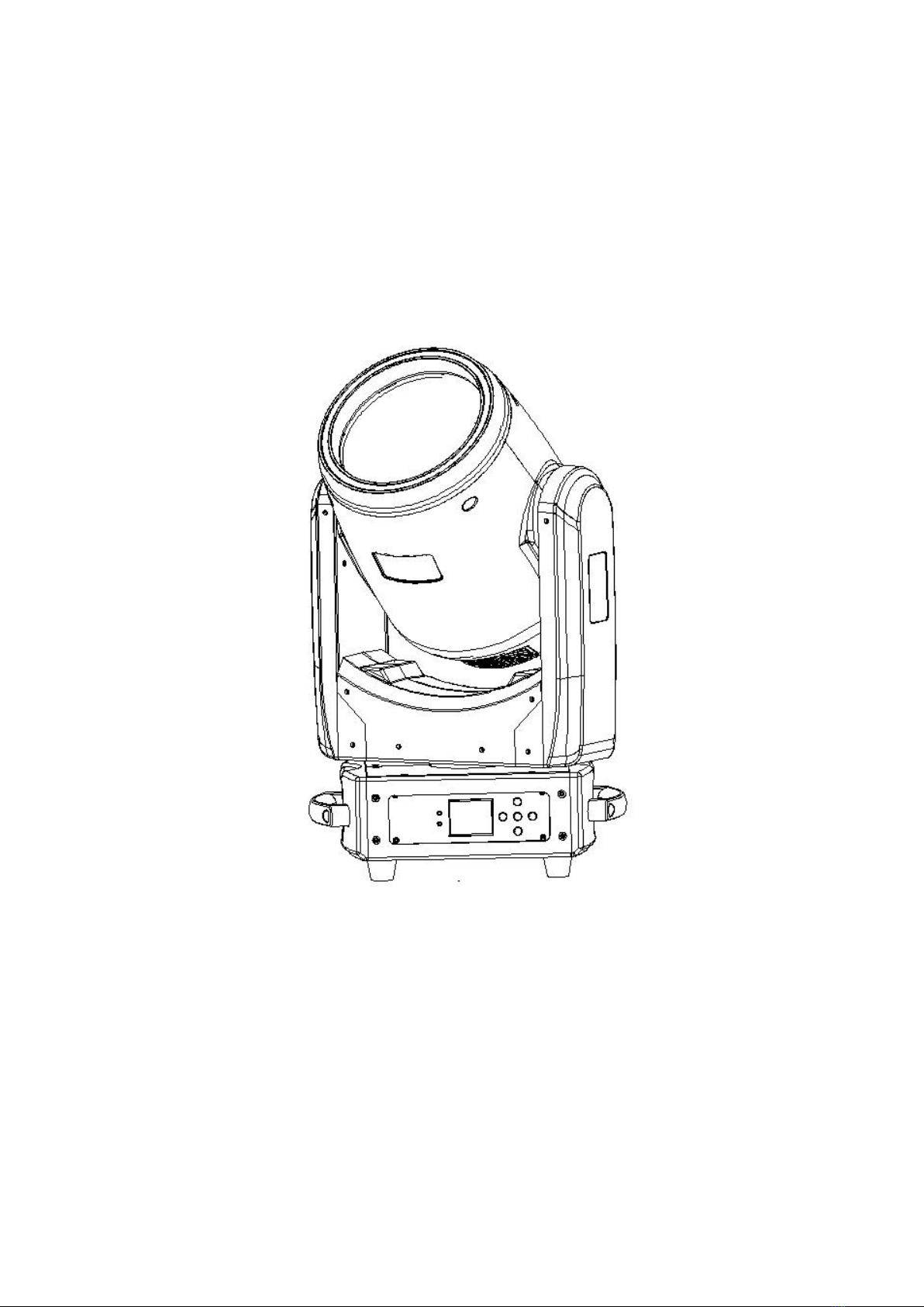
Features:
The appearance of the product is simple and exquisite, light weight, suitable for use in
multiple places, using high-brightness LED module light source, the light is sharp and the
spot is clear, using a two-in-one high-precision lens, the minimum light-emitting angle
reaches 1.3 degrees, a variety of stroboscopic effects, equipped with Atomization and
colorful functions, high standard constant current solution, strong uniformity of low
brightness, stable linear dimming, auto focus function, support RMD remote dialing
function, the light strip is equipped with 20 static effects and 51 dynamic effects. When
dialing the address code, press the up button in the menu to automatically increase the
number of channels, without calculating the address code of the next lamp, the lamp
automatically monitors the photocoupler and Hall data function, and has a temperature
self-check function, the lamp temperature reaches 40 degrees, the fan starts, The power
is reduced to 70 degrees to protect the life of the lamp beads.