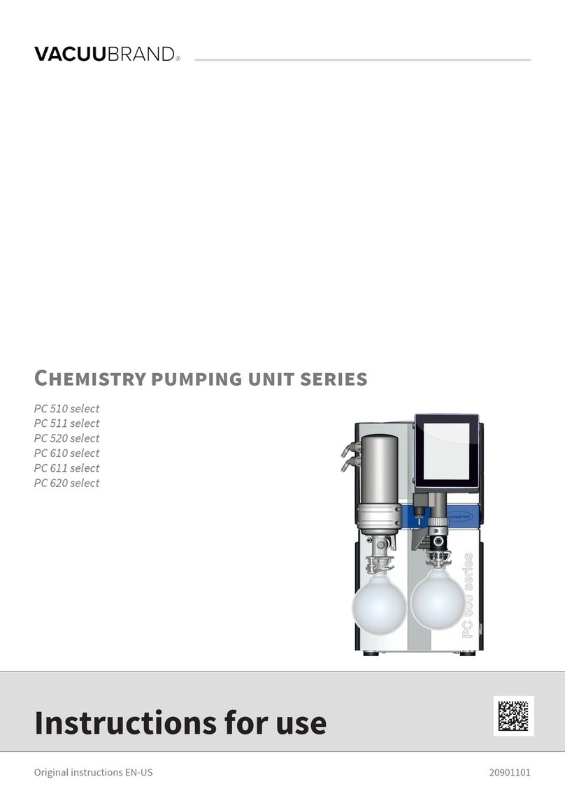
vacuubrand PC 510 NT User manual

page 2 of 106
After sales service:
Contact your local dealer or call +49 9342 808-193.
Dear customer,
Your VACUUBRAND diaphragm pumps are designed to provide you with
many years of trouble-free service with optimal performance. Our many
years of practical experience allow us tor provide a wealth of application
and safety information. Please read these instructions for use before the
initial operation of your pump.
VACUUBRAND diaphragm pumps combine our many years of experi-
ence in design, construction and practical operation, with the latest de-
velopments in material and manufacturing technology.
Our quality maxim is the ”zero fault principle”:
Every diaphragm pump, before leaving our factory, is tested intensively,
including an endurance run of 18 hours. Any faults, even those which oc-
cur rarely, are identied and can be eliminated immediately.
After completion of the endurance run, every pump is tested, and must
achieve specications before shipment.
We are committed to providing our customers only pumps that meet this
high quality standard.
While our pumps cannot eliminate all of your work, we design, manufac-
ture and test them to ensure that they will be an effective and trouble-free
tool to assist you in that work.
Yours,
VACUUBRAND GMBH + CO KG
Trademark index:
VACUU•LAN®, VACUU•BUSTM, VACUU•CONTROLTM, chemistry-
HYBRIDTM, PeltronicTM, TURBO•MODETM, VARIOTM, VARIO-SPTM,
VACUUBRAND®and also the shown company logos are trademarks of
VACUUBRAND GMBH + CO KG, Germany

page 4 of 106
Contents
Part I................................................................. 1
Reset / Language selection ............................................. 3
Safety information!............................................................. 6
Important information! ......................................................................... 6
General information............................................................................. 8
Intended use........................................................................................ 8
Setting up and installing the equipment .............................................. 9
Ambient conditions.............................................................................11
Operating conditions ......................................................................... 12
Safety during operation ..................................................................... 13
Maintenance and repair..................................................................... 17
Technical data................................................................... 19
Gas inlet temperatures..................................................................... 20
Wetted parts..................................................................................... 22
Abbreviations.................................................................................... 23
Pump parts....................................................................................... 23
Use and operation ............................................................ 28
Installing a pump in a vacuum system .............................................. 28
During operation................................................................................ 34
Important notes regarding the use of gas ballast .............................. 36
Important notes concerning the operation of the
exhaust waste vapor condenser ....................................................... 37
Shutdown & storage.......................................................................... 39
Vacuum controller CVC 3000 ............................................................ 40
Menu guide........................................................................ 45
Pump down function........................................................ 47
Vac Control function ........................................................ 49
Program function.............................................................. 52
Application example ......................................................................... 54
VACUULAN function ........................................................ 55
Application examples....................................................... 57
Vacuum for ltration and suction ...................................................... 57
Vacuum for gel dryer,
drying chambers and vacuum concentrators ................................... 58
Vacuum for distillation and evaporation (e.g., rotary evaporator) 58
Vacuum for VACUU•LAN networks .................................................. 59

page 5 of 106
Conguration.................................................................... 60
Readjustment of CVC 3000.............................................. 62
Calibration in the factory ................................................. 64
Cleaning the pressure transducer .................................. 65
Part II.............................................................. 66
Interface parameters ........................................................ 69
Setting of the interface ..................................................................... 70
Read commands ”CVC 2000” .......................................................... 71
Write commands ”CVC 2000” .......................................................... 72
Read commands ”CVC 3000” .......................................................... 74
Write commands ”CVC 3000” .......................................................... 76
Accessories ...................................................................... 79
Troubleshooting ............................................................... 82
Replacing diaphragms and valves.................................. 86
Cleaning and inspecting the pump heads ........................................ 88
Replacing the diaphragm ................................................................. 92
Replacing the valves ........................................................................ 94
Replacing the device fuse ................................................................ 99
Notes on return to the factory....................................... 100
Warranty .......................................................................... 103
Health and safety clearance form ................................. 104

page 6 of 106
Safety information!
Important information!
This manual is an integral part of the equipment de-
scribed herein. It describes the safe and proper use of
the vacuum pump. The manual consists of two parts.
Keep this manual complete and accessible to person-
nel at all times!
Make operating personnel aware of dangers arising
from the pump and the pumped substances.
Read this manual carefully before installing or oper-
ating the equipment. Observe the instructions con-
tained in this manual.
VACUUBRAND disclaims any liability for inappro-
priate use of these pumps and for damage resulting
from disregarding the instructions contained in this
manual.
Do not modify the equipment without authorization.
This manual is only to be used and distributed complete-
ly and unchanged. It is strictly the users’ responsibility to
check carefully the validity of this manual with respect to
his product.
Manual-no.: 999220 / 05/20/2010
The following signal word panels and safety
symbols are used throughout this manual:
This is the safety alert symbol. It is used to alert you to po-
tential personal injury hazards. Obey all safety messages
that follow this symbol to avoid possible injury and death.
NOTICE

page 7 of 106
➨DANGER indicates a hazardous situation which, if not
avoided, will result in death or serious injury.
+WARNING indicates a hazardous situation which, if not
avoided, could result in death or serious injury.
• CAUTION indicates a hazardous situation which, if not
avoided, could result in minor or moderate injury.
NOTICE is used to address practices not related to per-
sonal injury.
Caution! Hot surface!
Disconnect equipment from AC power.
Dispose off electronic equipment according to regula-
tions.
NOTICE
Formatting used in this manual:
Note: The signal word panels in all sections of this manual always refer
to all paragraphs of the same format (➨/ + / • / plain text) following each
signal word panel.

page 8 of 106
General information
Remove all packing material from the packing box. Re-
move the product from its packing-box and retain all pack-
aging until the equipment is inspected and tested. Re-
move the protective caps from the inlet and outlet ports
and retain for future use. Inspect the equipment promptly
and carefully.
If the equipment is damaged, notify the supplier and the
carrier in writing within three days. Retain all packing ma-
terial for inspection. State the item number of the product
together with the order number and the supplier’s invoice
number. Failure to check and give notice of damage will
void any and all warranty claims for those deciencies.
Replace the protective caps, if the equipment is not used
immediately. Store the equipment in dry and non-corrosive
conditions (see also ”Technical data”, pg. 19).
Use the mounted handle or the recessed grips when mov-
ing the pump.
+Do not use any damaged equipment.
Intended use
+Do not use the pump or any system parts on humans
or animals.
+Prevent any part of the human body from coming into
contact with vacuum.
+Ensure that the individual components are only con-
nected, combined and operated according to their de-
sign and as indicated in the instructions for use.
+Comply with all notes on correct vacuum and electrical
connections; see section ”Use and operation”, pg. 28.
+Use the equipment only as intended, that is, for gen-
eration, measurement, and control of vacuum in ves-
sels designed for that purpose. Any other use will auto-
matically invalidate all warranty and liability claims.
Remain aware of safety and risks.
NOTICE

page 9 of 106
+Do not use the pump to generate pressure.
The pumps are designed for operation at ambient temper-
atures between +50°F and +104°F (+10°C and +40°C).
Check the maximum temperatures if installing the pump in
a cabinet or a housing. Make sure ventilation is adequate
to maintain recommended operating temperature. Install
an external automatic ventilation system if necessary. If
pumping hot process gases, make sure that the maximum
permitted gas inlet temperature is not exceeded. The max-
imum permitted gas inlet temperature depends on several
parameters like inlet pressure and ambient temperature
(see ”Technical data”, pg. 19).
Do not aspirate particles and dust.
Do not pump liquids.
Ensure that the pump is chemically resistant to the pumped
substances prior to operation.
Setting up and installing the equipment
➨Equipment must be connected only to a suitable elec-
trical supply and a suitable ground point. As such,
the plug must be plugged into an outlet that is properly
grounded. Failure to connect the motor to ground may
result in deadly electrical shock.
The supply cable may be tted with a molded Euro-
pean IEC plug or a plug suitable for your local electrical
supply. The cable contains wires color coded as fol-
lows: green or green and yellow: ground; blue or white:
neutral; brown or black: hot.
+Due to the high compression ratio, the pump may gen-
erate overpressure at the outlet. Check pressure com-
patibility with system components (e.g., exhaust pipe-
line or exhaust valve) at the outlet.
+Do not permit any uncontrolled pressurizing.
Make sure that the exhaust pipeline cannot become
NOTICE

page 10 of 106
blocked. If there is an exhaust isolation valve, make
sure that you cannot operate the equipment with the
valve closed to avoid a risk of bursting!
+Always provide a free and pressureless exhaust outlet
to avoid damage to pump valves and risk of bursting of
condenser glassware.
+Check the overpressure safety relief device at the ex-
haust waste vapor condenser at appropriate intervals.
• Provide a rm, level platform for the equipment. Check
that the system which you are going to evacuate is
mechanically stable. Check that all ttings are secure.
Ensure a stable position of the pump without any me-
chanical contact other than the pump feet. Comply with
all applicable safety regulations.
• Comply with maximum permissible pressures at in-
let and outlet and with maximum permissible pres-
sure differences between inlet and outlet. See section
”Technical data”, pg. 19. Do not operate the pump with
overpressure at the inlet.
• Comply with maximum permissible pressures at the
pressure transducer. See section ”Technical data”, pg.
19.
• Avoid overpressure of more than 2.9 psi (0.2 bar) in the
event that inert gas is connected to the pump, to the
gas ballast or to a venting valve.
• Ensure that the coolant outlet pipe is always free and
that it cannot get blocked. If installing an optional cool-
ant valve, it must always be in the supply line of the
exhaust waste vapor condenser.
• Keep the electrical power cord away from heated sur-
faces.
• Note: Flexible elements will shrink when evacuated.
Check the power source and the pump’s rating plate to be
sure that the power source and the equipment match in volt-
age, phase, and frequency.
Check fan regularly for dust/dirt. Clean fan guard grill if
NOTICE

page 11 of 106
necessary to avoid a reduction of ventilation.
Do not place the pumping unit on soft surfaces (e.g., rub-
ber foam) during operation. This may reduce or block the
fans’ air supply. Keep a minimum distance of 8 in (20 cm)
between the cooling fan and surrounding items (e.g., hous-
ing, walls, etc.). Do not cover the pumping unit.
Use only hoses at the inlet and outlet of the pump with
an inner diameter at least as large as the diameter of the
pump’s tubing (to avoid overpressure at the outlet, and
reduction of pumping speed at the inlet).
Connect hoses gas tight at inlet and outlet of the pump.
Secure coolant hoses at the hose nozzles (e.g., with hose
clamp) to prevent their accidental slipping.
Allow the equipment to equilibrate to ambient temperature
if you bring it from cold environment into a room prior to
operation. Notice if there is water condensation on cold
surfaces.
Check liquid level in catchpots regularly and drain con-
densate in time to avoid overlling. A level sensor can be
purchased to trigger an alarm when the catchpot is full
(see ”Accessories”, pg. 79).
Ensure that no foreign objects can be drawn into the
pump.
Comply with all applicable and relevant safety require-
ments (regulations and guidelines). Implement the re-
quired actions and adopt suitable safety measures.
Ambient conditions
+Do not use this product in an area where it can fall or
be pulled into water or other liquids.
➨Do not reach for this product if it has fallen into liquid.
There is a risk of deadly electrical shock. Unplug the
system immediately.

page 12 of 106
To the best of our knowledge the equipment is in compli-
ance with the requirements of the applicable EC-directives
and harmonized standards (see ”Declaration of Conformi-
ty”) with regard to design, type and model. Directive IEC
1010 (EN 61010-1) gives in detail the conditions under
which the equipment can be operated safely (see also IP
degree of protection, ”Technical data”, pg. 19).
Adopt suitable measures in case of differences from rec-
ommended conditions, e.g., using the equipment outdoors,
installation in altitudes of more than 3300 ft (1000 m) above
mean sea level, conductive pollution or external conden-
sation on the pump.
Pay attention to the permissible maximum ambient and
gas inlet temperatures (see ”Technical data”, pg. 19).
Do not operate this product near ames.
Operating conditions
➨These pumps are not approved for operation in po-
tentially explosive atmospheres. Do not operate the
pumps in potentially explosive atmospheres.
➨These pumps are not approved for the pumping of
potentially explosive atmospheres. Do not pump
potentially explosive atmospheres.
➨The pumps are not suitable to pump any of the sub-
stances listed below.
Do not pump:
- unstable substances
- substances which react explosively under impact
(mechanical stress) without air
- substances which react explosively when being ex-
posed to elevated temperatures without air,
- self inammable substances,
- substances which are inammable without air
- explosive substances.
NOTICE

page 13 of 106
Do not pump substances which may form deposits in-
side the pump. The pumps are not suitable for pumping
substances which may form deposits inside the pump. De-
posits and condensate in the pump may lead to increased
temperatures even to the point of exceeding the maximum
permitted temperatures.
Check the inlet and outlet of the pump, if there is a danger of
forming deposits inside the pump, e.g., in the pump cham-
bers (the pump chamber is the part between diaphragm
and head cover. See section ”Replacing diaphragms and
valves”, pg. 86). Inspect the pump chambers regularly and
clean if necessary.
The pumps are not suitable for pumping dust and they
are not approved for operation below ground.
Do not pump dust and do not operate the pump below
ground.
When changing the substances pumped, we recommend
to purge the pump with air or inert gas prior to changing
the pumped media. Purging the pump will pump out resi-
dues and it will reduce the possibility of reactions of the
pumped substances with each other and with the pump’s
materials.
Consider interactions and chemical reactions of the
pumped media. Ensure that the materials of the pump’s
wetted parts are compatible with the pumped substances,
see section ”Technical data”, pg. 19.
Safety during operation
➨Adopt suitable measures to prevent the release of dan-
gerous, toxic, explosive, corrosive, noxious or polluting
uids, vapors and gases. To prevent any emission of
such substances from the pump outlet, install an ap-
propriate collecting and disposal system and take pro-
tective action for pump and environment.
NOTICE

page 14 of 106
+Never operate this pump if it has a damaged cord or
plug. If the pump is not working properly, has been
dropped or has fallen into water, contact your pump
service provider.
+Prevent any part of the human body from coming into
contact with vacuum.
+Make sure that the exhaust pipeline cannot become
blocked.
+Check the overpressure safety relief device at the ex-
haust waste vapor condenser at appropriate intervals.
+Attention: At pressures above approximately 795 Torr
(1060 mbar) the pressure reading becomes incorrect
due to saturation of the pressure transducer. The dis-
play ashes. Release pressure immediately! Risk of
bursting!
+You must take suitable precautions to prevent any for-
mation of explosive mixtures in the pump chamber or
at the outlet of the pump. In case, e.g., of a diaphragm
failure, mechanically generated sparks, hot surfaces or
static electricity may ignite these mixtures. Use inert
gas for gas ballast or venting, if necessary.
+Drain appropriately or otherwise remove any potentially
explosive mixtures at the outlet of the pump, or dilute
them with inert gas to non-explosive concentrations.
+Comply with applicable regulations when disposing of
chemicals. Take into consideration that chemicals may
be contaminated. Take adequate precautions to pro-
tect people from the effects of dangerous substances
(chemicals, thermal decomposition products of uo-
roelastomers). Use appropriate protective clothing and
safety goggles.
+Use only original manufacturer’s spare parts and
accessories. Otherwise the safety and performance of
the equipment, as well as the electromagnetic compat-
ibility of the equipment might be reduced.
The CE mark or the cTÜVus mark may be voided if not

page 15 of 106
using original manufacturer’s spare parts.
• Ensure that no parts of your clothing, hair or ngers can
be caught or drawn in at the inlet of the pump. Never
insert ngers or drop any other object into the inlet or
outlet.
•Pay attention to the safety symbol ”hot surfaces” on
the equipment. Hot parts may cause burns if touched.
Adopt suitable measures to prevent any danger arising
from hot surfaces or electric sparks. Ensure that hot
surfaces of the pump do not cause burns. Provide a
suitable contact guard if necessary.
• Pumping at high inlet pressure may lead to overpres-
sure at the gas ballast valve. Pumped gases or con-
densate might be expelled if the valve is open. If an
inert gas supply is connected to the gas ballast, ensure
that its inlet pipeline is not contaminated.
• Ensure that the coolant outlet pipe at the waste va-
por condenser is always free and that it cannot get
blocked.
• Failure of the pump (e.g., due to power interruption),
failure of connected components or of parts of the sup-
ply, or a change of parameters must not be allowed to
lead to a dangerous situation under any circumstances.
In case of a diaphragm failure or in case of a leak in the
manifold, pumped substances might be released into
the environment or into the pump housing or motor.
Especially comply with notes on use and operation and
maintenance.
• The residual leak rate of the equipment might render
possible an exchange of gas, albeit extremely slight,
between the environment and the vacuum system.
Adopt suitable measures to prevent contamination of
the pumped substances or the environment.
• You must take suitable precautions to prevent any dan-

page 16 of 106
gerous situation from arising if the controller starts a
vacuum pump (in combination with a VMS Module A),
switches an in-line valve or a coolant valve, or opens a
venting valve.
• Attention: If the controller is set to Autostart, the pro-
cess will start immediately after a power failure with-
out pressing any further key. It is your responsibility to
ensure that automatic start-up of the system will not
lead to any dangerous condition. Provide appropriate
safety measures. Check prior to starting the process
whether the option ”Autostart” (menu: conguration) is
enabled.
Do not start the pump if the pressure difference between
inlet and outlet exceeds 16 psi (1.1 bar) at maximum.
Prevent the backpressure of gases and the backow of
condensates at the outlet.
Never aspirate liquids or dust into the pump.
Check the liquid level in the catchpots regularly and drain
condensate in time to prevent overlling. A level sensor
can be purchased to trigger an alarm when the catchpot is
full (see ”Accessories”, pg. 79).
Provide appropriate protective measures to allow for the
possibility of failure and malfunction. The protective mea-
sures must also allow for the requirements of the respec-
tive application.
The CVC 3000 controller is powered by a short circuit
proof wide-range power supply with integrated overload
protection.
In case of overload, the motor is shut down by a self-hold
thermal cutout in the winding.
Note: Only manual reset is possible. Press the START/
STOP key at the controller to conrm the error message.
Switch off the pump and disconnect from the power source.
Identify and eliminate the cause of failure. Wait approx.
NOTICE

page 17 of 106
ve minutes before restarting the pump.
• Note: In case of supply voltage below 100V, the lock
of the cutout might be impaired and the pump may
restart on its own after sufcient cooling down. Take
appropriate precautions, if an automatic restart of the
pump may lead to a dangerous situation.
The A-weighted emission sound pressure level of the
pump does not exceed 70 dB(A). Measurement according
to EN ISO 2151:2004 and EN ISO 3744:1995 with stan-
dard silencer or exhaust tube at outlet.
Maintenance and repair
In order to comply with laws (occupational, health and
safety regulations, safety at work law and regulations for
environmental protection) vacuum pumps, components
and measuring instruments can only be returned when
certain procedures (see section ”Notes on return to the
factory”, pg. 100) are followed.
Take advantage of our service seminars, which put special
focus on the maintenance and repair of vacuum pumps.
For details see www.vacuubrand.com.
Wear parts have to be replaced regularly. In case of
normal wear, the lifetime of the diaphragms and valves is
> 10000 operating hours. Bearings have a typical durabil-
ity of 40000 h. Motor capacitors have a typical durability
in the range of 10000 to 40000 h depending strongly on
operation conditions including ambient temperature, hu-
midity or load.
+Ensure that the pump cannot be operated acciden-
tally. Never operate the pump if covers or other
parts of the pump are disassembled. Never operate
a defective or damaged pump.
NOTICE

page 18 of 106
+Switch off the pump. Disconnect the electrical pow-
er cord and wait two minutes before starting mainte-
nance to allow the capacitors to discharge.
+Note: The pump may be contaminated with process
chemicals, which have been pumped during operation.
Ensure that the pump is completely decontaminated
before maintenance commences. Take adequate pre-
cautions to protect people from the effects of dangerous
substances if contamination has occurred. Use appro-
priate protective clothing, safety goggles and protective
gloves.
• Check every motor capacitor regularly by measuring
its capacity and estimating its time in operation. Re-
place old capacitors early enough to prevent a failure in
operation. If an old motor capacitor fails, the capacitor
may get hot. It may even melt or emit a ame, which
could be dangerous for persons and equipment in
the vicinity. The capacitors have to be replaced by an
electrician.
• Vent the pump before starting maintenance. Isolate the
pump and other components from the vacuum system.
Allow sufcient cooling of the pump. Separate the pump
from the coolant circuit and drain condensate, if appli-
cable.
• Ensure that maintenance is done only by suitably
trained and supervised technicians. Ensure that the
maintenance technician is familiar with the safety pro-
cedures, which relate to the products processed by the
pumping system.
Only dismantle the pump as far as necessary.

page 19 of 106
Technical data
Type
PC 510 NT
PC 511 NT
PC 520 NT
PC 610 NT
PC 611 NT
PC 620 NT
Maximum pumping speed
50/60 Hz (ISO 21360)* cfm
(m3/h) 1.2 / 1.4
(2.0 / 2.3) 2.0 / 2.2
(3.4 / 3.8)
Ultimate vacuum (abso-
lute) without gas ballast Torr
(mbar) 5.3
(7) 1.1
(1.5)
Ultimate vacuum (abso-
lute) with gas ballast Torr
(mbar) 9.0
(12) 2.3
(3)
Maximum permissible inlet
pressure (absolute) psi
(bar) 16
(1.1)
Maximum permissible out-
let pressure (absolute) psi
(bar) 16
(1.1)
Maximum pressure
difference between inlet
and outlet
psi
(bar) 16
(1.1)
Maximum permissible
pressure (absolute) at gas
ballast valve
psi
(bar) 17.5
(1.2)
Permissible ambient
temperature
storage / operation
°F
(°C) 14 to 140 / 50 to 104
(-10 to +60 / +10 to +40)
Permissible relative atmo-
spheric moisture during op-
eration (no condensation) % 30 to 85
Rated motor power hp
(kW) 0.24
(0.18) 0.34
(0.25)
No-load speed 50/60 Hz rpm 1500 / 1800
Maximum permissible range
of supply voltage ( ±10% )
Attention: Observe specications
of rating plate!
100-115 V~ 50/60 Hz, 120 V~ 60 Hz
230 V~ 50/60 Hz
Maximum rated current at:
100-115 V~ 50/60 Hz,
120 V~ 60 Hz
230 V~ 50/60 Hz A
A3.4
1.8 5.7
3.0
Device fuse 2 slow blow fuses 6.3A
Motor protection thermal cutout, manual reset
Degree of protection IEC 529 IP 40
* Pumping speed of diaphragm pump

page 20 of 106
Gas inlet temperatures
Operating condition Inlet pressure Permitted range of gas
temperatures at inlet
Continuous operation > 75 Torr (100 mbar)
(high gas load)
➨50 °F to 104 °F
(+10°C to +40°C)
Continuous operation < 75 Torr (100 mbar)
(low gas load)
➨32 °F to 140 °F
(0°C to +60°C)
Short-time
(< 5 minutes) < 75 Torr (100 mbar)
(low gas load)
➨14 °F to 176 °F
(-10°C to +80°C)
Type
PC 510 NT
PC 511 NT
PC 520 NT
PC 610 NT
PC 611 NT
PC 620 NT
Inlet hose nozzle for tubing I.D. 3/8“
(hose nozzle DN 10 mm)
Outlet hose nozzle for tubing I.D. 3/8“
(hose nozzle DN 10 mm)
Coolant connection
(waste vapor condenser)
hose nozzle for tubing
I.D. 1/4” - 5/16”
(hose nozzle DN 6-8 mm)
Maximum permissible
pressure of coolant at
waste vapor condenser
psi
(bar) 87 (absolute)
(6 (absolute))
Permissible range of cool-
ant temperature (waste
vapor condenser)
°F
(°C) 5 to 68
(-15 to +20)
Volume of catchpot
(only pumping unit) qt
(ml) 0.52
(500)
Dimensions L x W x H
approx.
PC 510 NT / PC 610 NT
PC 511 NT / PC 611 NT
PC 520 NT / PC 620 NT
in (mm)
in (mm)
16.5 x 9.6 x 17.5 (419 x 243 x 444)
17.1 x 9.6 x 17.5 (435 x 243 x 444)
17.1 x 14.2 x 17.5 (435 x 361 x 444)
Weight approx.
PC 510 NT / PC 610 NT
PC 511 NT / PC 611 NT
PC 520 NT / PC 620 NT
lbs. (kg)
lbs. (kg)
lbs. (kg)
36.8 (16.7)
37.3 (16.9)
39.0 (17.7)
43.9 (19.9)
44.3 (20.1)
46.1 (20.9)
Other manuals for PC 510 NT
1
This manual suits for next models
5
Table of contents
Other vacuubrand Laboratory Equipment manuals

vacuubrand
vacuubrand MV 10C NT VARIO o.C. User manual

vacuubrand
vacuubrand PC 2001 Vario User manual

vacuubrand
vacuubrand PC 511 NT User manual

vacuubrand
vacuubrand PC 510 select User manual

vacuubrand
vacuubrand BVC control Operating instructions

vacuubrand
vacuubrand VAC 24seven User manual

vacuubrand
vacuubrand VAC24SEVEN User manual

vacuubrand
vacuubrand ME 4C NT VARIO User manual

vacuubrand
vacuubrand VHC pro User manual

vacuubrand
vacuubrand BVC control User manual