VAF instruments Viscosense 3 Maintenance manual

Technical Manual
Instructions for installation,
operation and maintenance
775
VISCOSENSE
®
3
Viscosity Sensor & Interface box
Valid for ViscoSense®3
Publication nr TIB-775-GB-0517
Supersedes TIB-775-GB-1216

CONTENTS
1. PREFACE....................................................................................... 2
1.1 General ........................................................................................................2
1.2 Symbols .......................................................................................................3
1.3 Copyright .....................................................................................................3
2. SYSTEM DESCRIPTION................................................................ 4
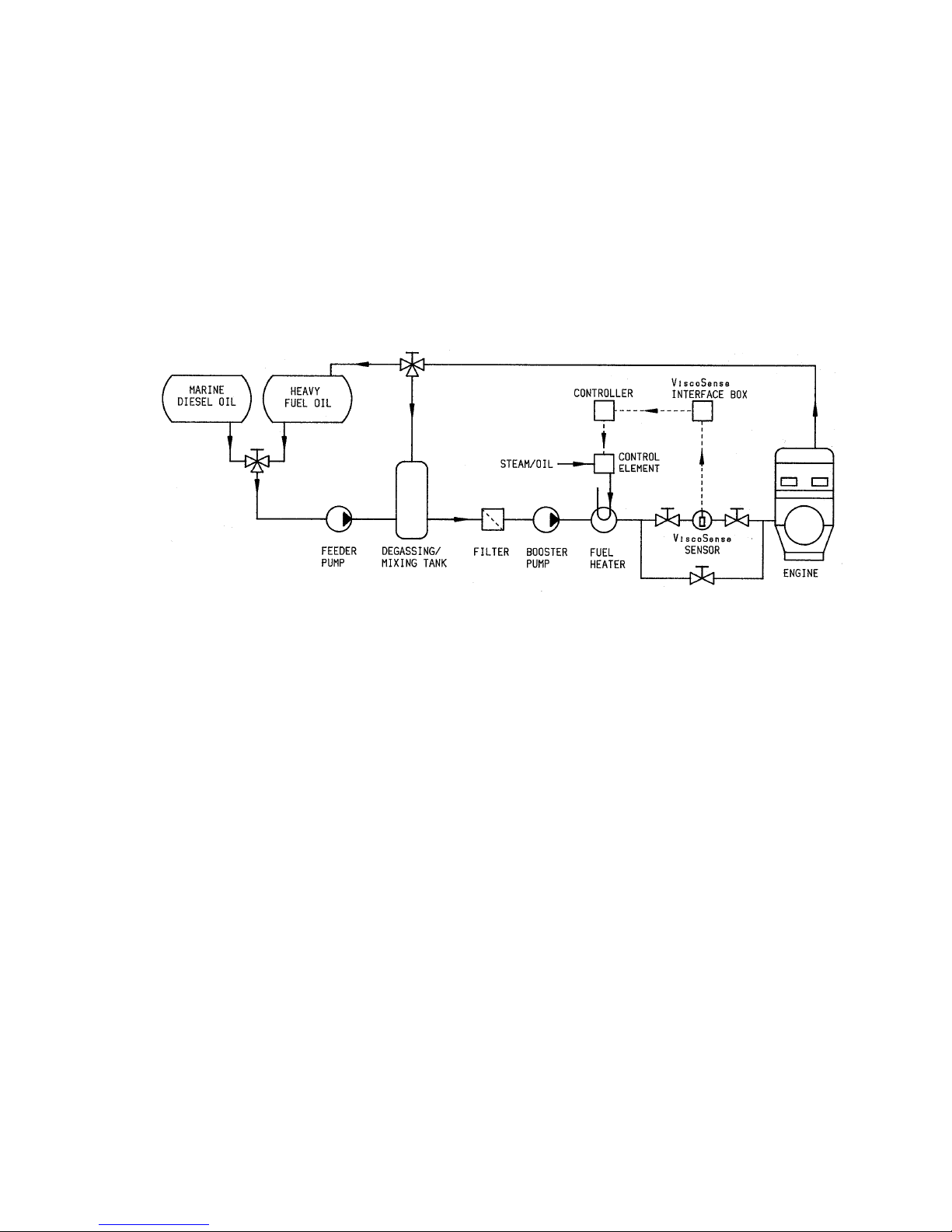
2.1 System description.......................................................................................4
2.2 System components ....................................................................................5
2.3 Principle of operation ...................................................................................6
3. TECHNICAL SPECIFICATION ....................................................... 7
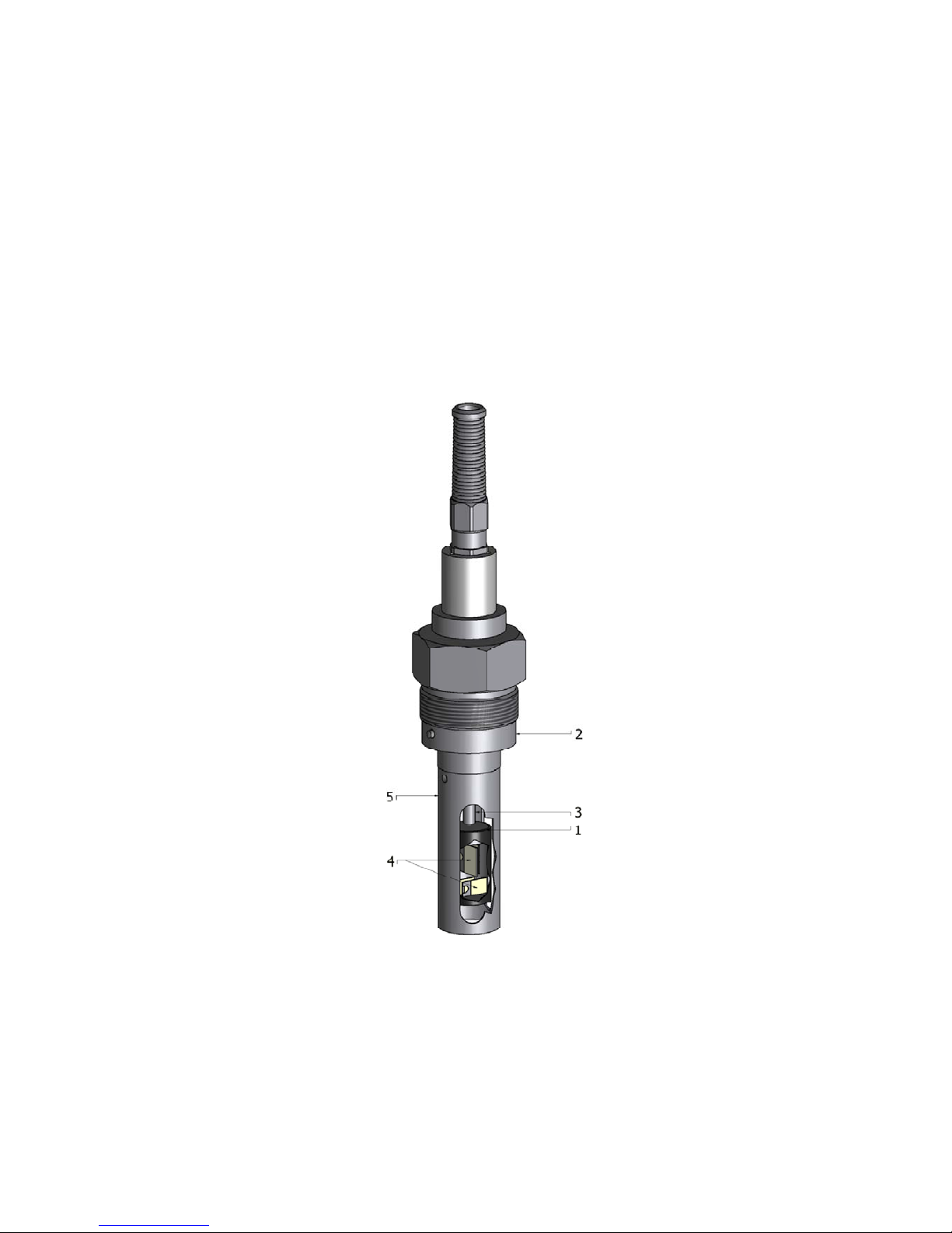
3.1 Sensor .........................................................................................................7
3.2 Sensor housing............................................................................................7
3.3 Interface box ................................................................................................8
4. SAFETY INSTRUCTIONS .............................................................. 8
4.1 Safety precautions .......................................................................................8
5. UNPACKING .................................................................................. 9
6. INSTALLATION .............................................................................. 9
6.1 To record nameplate data............................................................................9
6.2 Conditions for correct working of the ViscoSense®3 sensor ......................10
6.3 General installation recommendations.......................................................11
6.4 Mechanical installation...............................................................................11
6.4.1 ViscoSense®3interface box..............................................................11
6.4.2 ViscoSense®3 housing......................................................................11
6.4.3 To assemble ViscoSense®3 sensor ..................................................13
6.5 Electrical installation ..................................................................................15
6.6 Connection of sensor to interface box........................................................16
6.7 Installation checklist version 1.0.................................................................17
7. OPERATING INSTRUCTIONS..................................................... 19
7.1 Initial start-up .............................................................................................19
7.2 Shut-down on heavy fuel oil.......................................................................19
7.3 Shut-down on diesel oil..............................................................................19
7.4 Routine start-up .........................................................................................19
8. MAINTENANCE............................................................................ 20
8.1 Routine maintenance .................................................................................20
8.2 To clean the ViscoSense®3 sensor............................................................20
8.2.1 General procedure ............................................................................20
9. REPAIR OR REPLACEMENT ...................................................... 21
9.1 Repair ........................................................................................................21
9.2 Replacement..............................................................................................21
9.3 Procedure for using the micro SD card ......................................................21
10. TAKE OUT OF SERVICE ......................................................... 22
11. REMOVAL AND STORAGE OF EQUIPMENT......................... 23
12. MALFUNCTION AND SEND FOR REPAIR ............................. 23

1
13. ENVIRONMENT ....................................................................... 23
14. DISPOSAL................................................................................ 23
15. TROUBLE SHOOTING............................................................. 24
15.1 Disconnection the sensor........................................................................24
15.2 General trouble shooting.........................................................................25
15.3 PI setting errors (for additional viscosity controller).................................27
15.4 How to take a HFO sample for analysis..................................................27
15.5 Diagnostic information ............................................................................28
16. CERTIFICATES........................................................................ 30
17. DRAWINGS .............................................................................. 31
17.1 ViscoSense®3 sensor and sensor housing .............................................31
17.1.1 ViscoSense®3sensor housing with sensor installed.........................31
17.2 ViscoSense®3interface box....................................................................32
17.2.1 ViscoSense®3interface box..............................................................32
18. ABBREVIATIONS..................................................................... 33
19. PARTS LISTS........................................................................... 34
19.1 ViscoSense®3 sensor .............................................................................34
20. WARRANTY CONDITIONS...................................................... 35
21. ENCLOSURE ........................................................................... 37
21.1 Recommendations for a good working booster unit ................................ 37

2
1. PREFACE
1.1 GENERAL
This manual contains instructions for installation, operation and maintenance (IOM) of the VAF
ViscoSense®3 viscosity sensor (VS3) and interface box.
For IOM information of associated equipment supplied by VAF Instruments, refer to the separate
manual supplied with those products.
This manual contains important information for the installer, the operator and for your maintenance
department.
Never use the equipment outside its specifications or beyond common engineering practice
nor use the equipment for other applications or make connections to other equipment than
explicitly described in the order acknowledgement and/or technical manuals of VAF
Instruments.
It is not allowed to make any modifications to the sensor or the interface box without prior
written permission of VAF Instruments BV.
To ensure safe and correct installation and operation, read this manual completely before
installing the equipment and starting operations.
ViscoSense®2and ViscoSense®3 sensor (from serial numbers 70000) and interface box
(from serial numbers 1480000) are not interchangeable with previous model ViscoSense®.
ViscoSense®2and ViscoSense®3 sensor and interface box are interchangeable.
For any additional information contact:
VAF Instruments B.V. Tel. +31 78 618 3100
Vierlinghstraat 24, 3316 EL Dordrecht Fax +31 78 617 7068
The Netherlands Internet: www.vaf.nl
Or your local authorized VAF dealer.
Their addresses can be found on www.vaf.nl

3
1.2 SYMBOLS
The following symbols are used to call attention to specific types of information.
A warning to use caution! In some instances, personal injury or damage to the
ViscoSense®3 unit or control system may result if these instructions are not followed
properly.
An explanation or information of interest.
Warning for hazardous voltages. Symbol is used on the interface box in combination with
the requirement to switch of the power supply to the box before opening it, in order to
avoid personal injury.
1.3 COPYRIGHT
This technical manual is copyrighted with all rights reserved.
While every precaution has been taken in the preparation of this manual, no responsibility for errors or
omissions is assumed. Neither is any liability assumed for damages resulting from the use of the
information contained herein. Specifications can be changed without notice.
ViscoSense®is a registered trademark of VAF Instruments B.V.

4
2. SYSTEM DESCRIPTION
2.1 SYSTEM DESCRIPTION
ViscoSense®3 is, besides other applications, intended for use in fuel oil treatment systems to obtain a
correct measurement and control of the fuel oil viscosity.
Figure 1 shows a typical fuel treatment system with return line from the engine. In this system, the
degassing/mixing tank operates as a fuel buffer, ensuring gradual changes of viscosity which results
in a stable control of the viscosity. The ViscoSense®3 sensor is used to measure the actual viscosity
of the fuel oil. The signal from the sensor is compared to the setpoint of a viscosity controller, which
regulates the output of the fuel heater via a control element (steam or thermal oil valve, or electric
heater cabinet).
Figure 1 Typical example of an automatic control system using steam or thermal oil heater

5
2.2 SYSTEM COMPONENTS
The ViscoSense®3 viscosity system consists of:
the combined viscosity and temperature measuring sensor
the sensor housing
Interface box
The sensor housing is made of ductile iron and has flanges for direct mounting in the fuel line. The
sensor itself is made of stainless steel and is mounted in the housing. The sensor head has a special
DLC coating and it is mechanically protected by a stainless steel flow tube with 3 oval slits. It is
supplied with 5 metres of signal cable for connection to the interface box.
The ViscoSense®3 Interface box is a wall mount electronic unit, processing the signals to and from
the sensor. It provides 4...20 mA signals for remote read-out of viscosity and temperature for a
flowcomputer, controller or other system elements. See separate technical manuals for a description
of these components.
Figure 2 ViscoSense®3 components (sensor in housing and interface box)

6
2.3 PRINCIPLE OF OPERATION
The operating principle of the sensor is that of a torsion pendulum. The sensor consists of a stainless
steel driver / sensor head (1), attached to the base plate (2) by means of a tubular torsion spring (3).
In the head, one pair of piezo elements (driver piezos) (4) actuates the pendulum at its torsional
resonance frequency, while another pair (the receiver piezos) probes the actual movement of the
head. In a low viscosity medium, like air the resonance frequency is in the range of 1600 Hz. In a high
viscosity medium the movement of the head is damped by the liquid. Consequently, the resonance
frequency slightly shifts towards lower frequencies, whilst the width of the resonance peak increases,
which is a measure for the viscosity.
A flow tube (5) is placed around the pendulum, to protect it against mechanical damage.
The flow tube is machined with a smooth surface, as well as with a triplet of oval slits. These slits
increase the refreshing rate between sensor and flow tube.
Figure 2 ViscoSense®3 sensor (VS3)

7
3. TECHNICAL SPECIFICATION
3.1 SENSOR
Sensor type nr. 0279-0096
Viscosity range 0 - 25/50 mPa.s (other ranges on request)
Temperature range 0-200°C
Maximum operating temperature 180C
Temperature transmitter PT 100 element
Accuracy
Viscosity +/- 2% instantaneous or 0.5 mPa.s
Temperature ± 1C
Material
Sensor Stainless steel 316L
Coating Diamond Like Carbon (DLC)
Signal cable length 5 metres, integrated with sensor
Protection class IP65
Weight 1 kg
Warning
For hazardous zone I and II, the ViscoSense®3 Ex d version is required.
(See separate technical manual TIB-777)
3.2 SENSOR HOUSING
Material housing ductile iron
Flange connections DN 50 mm (2”), DIN, ANSI or JIS
DN 65 mm (2,5”), DIN, ANSI or JIS
DN 80 mm (3”), DIN, ANSI or JIS
DN 100 mm (4”), DIN, ANSI or JIS
Maximum pressure rating 40 bar
Weight 2” approx. 10 kg
2,5” approx. 11 kg
3” approx. 12 kg
4” approx. 13 kg

8
3.3 INTERFACE BOX
Interface box type nr. 0279-0112
Supply voltage 100-230 VAC, 50/60 Hz
(Fluctuations should not exceed ±10% of the nominal value)
Power consumption 6 Watt
Internal battery Lithium coin type 3V rechargeable, 5 mAh, 6,8 mm
(Do not exchange without prior consulting VAF Instruments)
Output
Viscosity Isolated active output 4…20 mA, current loop, max. load 400Ω
Range typ. 0 - 25/50 mPa.s (depending on selected range)
Temperature Isolated active output 4…20 mA, current loop, max. load 400Ω
Range typ. 0 - 200° C
Response time Depending on application
Resolution 0,1 mPa.s and 0,1 g/l
Ambient temperature -20 .. + 55 C
Humidity range 0-95% RH
Protection class IP 66
Mounting Wall mounting
Cable connections
Power supply M20 x 1,5, Ø9-13 mm
Output signals M20 x 1,5, Ø9-13 mm
Sensor M16 x 1,5, Ø5-9 mm, integrated with sensor cable
Cable wire
Power supply 3 x 1.5 mm², double isolated heavy duty PVC
Output signals 3 x 2 x 0,50 mm², twisted pair, individually screened, braid shielded
Ventilation requirements No special requirements
Weight 2,0 kg
Max. altitude for use 2000 m above sea-level
4. SAFETY INSTRUCTIONS
4.1 SAFETY PRECAUTIONS
To ensure the safety of personnel and equipment:
Always follow the safety and installation recommendations in this manual.
Always use personal protective means when working with hot, aggressive and toxic process
liquids.
Always use insulated tools when working on electrical installations.
Ensure that local safety regulations are met when installing and operating the equipment.
All personnel who operate and service the equipment should read this manual completely and
make themselves acquainted with the equipment before installing or operating the equipment.
The ViscoSense®3 sensor body will heat up to the process temperature; do not touch the body
housing while process is running!

9
5. UNPACKING
Let the instruments acclimatize in the location where they are going to be installed for at least one
hour inside their shipment box. This is to avoid moisture buildup inside the instrument, or on the
connectors and wires.
When the equipment is taken out of the box, please leave the transport locking cap and the outside
protection, in place as long as possible to avoid any damage.
The ViscoSense®3 sensor has a special DLC coating on the pendulum.
Damage of the coating will influence the working of the sensor.
Special care should be taken not to scratch or damage the DLC coating.
The transport locking cap and the outside protection should be stored, in the unlikely event the
equipment has to be returned for repair.
Dispose of the packing material should be done according to the laws of the country where the
equipment is installed, or according to the rules that are applicable on the vessel.
Figure 4 Transport locking cap Figure 5 Outside protection
6. INSTALLATION
6.1 TO RECORD NAMEPLATE DATA
Before installing a ViscoSense®3 system, record type and serial numbers as stamped on the
ViscoSense®3 sensor and interface box.
Always quote the instrument serial number and the variant number when contacting the
factory or local service representative.
Never exceed the temperature and pressure limits specified on the nameplate of the
ViscoSense®3. Consult the factory if the ViscoSense®3 must be used for a different
process liquid than originally ordered.
A ViscoSense®3 unit may be part of a complete VAF viscosity control system. For information and
instructions covering the other components of this system, refer to the separate technical manuals as
supplied with these components.

10
For identification purposes it is recommended to record also nameplate data of
other ViscoSense®3 system components here.
Housing
Serial number: ……………………………
Variant: ……………………………………
Sensor
Serial number: ……………………………
Interface box
Serial number: ……………………………
Model: ……………………………………
6.2 CONDITIONS FOR CORRECT WORKING OF THE VISCOSENSE®3 SENSOR
The flow is recommended to be in-between the maximum and minimum fluid flow rate as mentioned
in chapter 21.1.
The ViscoSense®3housing should be placed in such a way, that no air can be trapped in the housing.
This can easily happen if the inner diameter of the piping is smaller than the inner diameter of the
ViscoSense®3housing, if it has been installed horizontally.
If the inner diameter of the piping is smaller than the inner diameter of the ViscoSense®3housing, the
transitions between the two diameters should be tapered. The inner diameter of the ViscoSense®3
housing should not be smaller than the piping.
The fluid should be homogenous.
It should not contain any air bubbles or foam.
THE FLUID SHOULD NOT CONTAIN ANY CHEMICALS OR SOLID PARTICALS THAT
CAN DAMAGE THE DLC COATING
THE FUEL SHOULD BE IN COMPLIANCE WITH ISO 8217:2010
(SPECIFICATIONS OF MARINE FUELS)

11
6.3 GENERAL INSTALLATION RECOMMENDATIONS
Mount the ViscoSense®3housing as low as possible, in the fuel system.
Compare your process variables with the specifications. Make sure these are compatible!
Pressure pulsations and variations should be avoided as much as possible.
Mechanical vibrations should be avoided as much as possible.
No special tools are required to install the ViscoSense®3. Ensure that your standard tools
are fit for the job.
Make sure that the working environment is clean. Ensure that no dirt can enter the sensor.
Insulate the pipes and the sensor housing well, to avoid any temperature loss of the fluid.
When fuel viscosity is 500 mPa.s or thicker it is recommended to wrap steam tracing with
sufficient capacity, or 20 Watts/metre resistance wiring around the ViscoSense®3housing.
VAF ViscoSense®3 sensor and interface box are precision instruments. Handle them with
care.
Do not unscrew the cable gland on the top of the ViscoSense®3 sensor or disconnect the
cable from the sensor. This will violate the correct operation of the ViscoSense®3 sensor.
Take care that the pendulum is not damaged and the torsion tube not bent by
mechanical force.
This will violate the ViscoSense®3 signal.
6.4 MECHANICAL INSTALLATION
6.4.1 ViscoSense®3interface box
1. Install the ViscoSense®3interface box in a suitable location, free from excessive vibrations,
humidity and excessive temperature variations.
2. The maximum distance between sensor and the interface box is determined by the cable length
from the sensor, being approx. 5 metres.
3. Allow sufficient space for installation of cables and for servicing.
4. The surface on which the interface box is mounted should at least be able to bear a weight of 10
kg.
6.4.2 ViscoSense®3 housing
1. Remove dust caps from sensor housing and install housing stress-free, with shut-off valves and
bypass valve in the fuel piping as illustrated in figure 6. Take care that the flow direction is in
accordance with the indication on the housing (inlet, outlet and arrow) as illustrated in figure 8.
Support inlet and outlet piping sufficiently.
These shut-off valves and bypass valve are not furnished by VAF Instruments.
2. Note that the distance between fuel heater and sensor housing inlet should not exceed 4 metres.
3. To protect the instrument from excessive vibrations, which can cause malfunctioning of the
instrument, it is recommended to:
Install the ViscoSense®3 as low as possible in the fuel system close to a solid structure or beam.
Install suitable pipe clamps at both sides of the ViscoSense®3 sensor housing.

12
4. Allow at least 50 cm clearance to the sensor housing, to be able to take out the measuring sensor
for service.
5. The sensor needs a stable environment to act as a counterweight for the pendulum movement.
The support must prevent movement and excessive vibrations of the ViscoSense®3housing,
especially movement in the direction of the pendulum movement (see drawing- angular movement
around the sensor axis). Therefore there must be two supports to the inlet and outlet perpendicular
to the pipe and perpendicular to the ViscoSense®3. If one support would be used the lateral
vibrations would be converted to angular vibrations and the situation would be made worse instead
of better.
Figure 6 Sensor installation diagram
The angular position of the supports must always be 90° in relation to the sensor.
The distance from the flange to the support should be two times the diameter of the pipe.
ViscoSense
®
3 housing size T. Max. L. Max.
50 mm (2”) 350 mm 150 mm
65 mm (2 ½”) 400 mm 160 mm
80 mm (3”) 400 mm 165 mm
100 mm (4”) 450 mm 185 mm
Figure 7 Sensor installation diagram

13
6.4.3 To assemble ViscoSense®3 sensor
1. Check the O-ring for damage, before installing the ViscoSense®3 sensor. Replace if necessary.
Make sure only one original o-ring is installed.
2. Remove transport locking cap from bottom side of flow tube.
3. Please make sure not to damage the DLC coating during installation.
Without the transport locking cap the sensor is not protected against excessive
mechanical shocks which can occur during handling.
4. Install sensor carefully in housing with the closed surface facing the flow, illustrated in figure 8.
Make sure the flow tube closed surface is pointing towards the inlet of the sensor
housing, see figure 8.
The sensor will not work correctly if installed wrongly.
Check if the position of the hole inside the housing and the fixation pin on the sensor
match.
5. Tighten the nut (1) by hand. If there is a temperature difference between the sensor and the
housing you should wait until they have the same temperature before tightening the nut.
6. Tighten the nut (1) with a wrench with a recommended torque of 100 Nm.
Make sure that all flange bolts and nuts are tightened correctly before re-pressurizing the
system.
See chapter 15.1

14
7. The ViscoSense®3 system is now ready for electrical installation.
Figure 8 ViscoSense®3 sensor assembly
A
B

15
6.5 ELECTRICAL INSTALLATION
Provide correct power supply to the interface box.
In order to maintain proper EMC protection a shielded cable should be used for 4-20 mA
output signals. Recommended cable: 0,50 mm², twisted pair, individually screened, braid
shielded and PVC insulated.
For correct installation a suitable isolation switch shall be installed in the supply line as
near as possible to the equipment. Maximum fuse current 16A.
To avoid signal grounding problems it is not recommended to connect more than one
device to each 4-20 mA output of the interface box.
1. Remove cover from interface box.
Check that the power supply is connected to terminal J2 in accordance with power
supply source and assure that power can be interrupted by a connector in the cable or
circuit breaker in the proximity of the interface box.
Make sure that the wire to PE is always longer than power wires.
Figure 9 Power supply terminal J2
2. Feed the cable from ViscoSense®3 sensor through gland and connect wires to terminal J6 in
accordance with figure 12.
3. Feed the cable for 4-20 mA viscosity, temperature and density output signals through the cable
glands and connect wires to terminal J1 in accordance with figure 12. When no temperature output
is connected to 3 and 4 on J1 (figure 12), terminals 3 and 4 must be connected together with a wire
link.
4. Feed the cable for power supply through the cable gland and connect the wires to terminal J2 in
accordance with figure 12.
To maintain proper EMC protection the cable glands provided with the interface box
should not be exchanged for cable glands of any other make/type.
5. Make sure that all connectors are properly seated before closing the cover again.
6. Close the cover of the interface box.

16
6.6 CONNECTION OF SENSOR TO INTERFACE BOX
1. Tighten the cable glands with a spanner
2. Install the wires to the appropriate terminals of
terminal J6
Figure 11 Connecting sensor to interface box
Figure 12 External connections at interface box

17
6.7 INSTALLATION CHECKLIST VERSION 1.0
ViscoSense
®
Sensor:
Yes No
The ViscoSense® housing has been installed according the below set-up.
(Mark what is correct)
Capacity circulation fuel pomp _________ m3/h
Does the ViscoSense® housing size match the capacity circulation fuel pomp?
DN50 max. 20m3/h
DN65 max. 34m3/h
DN80 max. 51m3/h
DN100 max. 80m3/h
Has the ViscoSense
®
housing been installed correct according the fuel flow direction?
Has the inlet and outlet piping sufficiently been supported (as per 6.4.2)?
Have fuel pressure dampers been installed at the engine?
Is a pressure regulating valve installed within the fuel system ?
Is an air pocket present in the mixing tank?
Have isolating and bypass valves been installed at the ViscoSense
®
sensor?
Has the ViscoSense® interface box been installed away from the heater?
The ambient temperature at the ViscoSense
®
interface box is not higher than 55⁰C?

18
Have all electric connections for external signals been made with a twisted pair shielded
cable and shields connected at one end only?
Are the original cable glands used at the ViscoSense
®
interface box?
ViscoSense
®
Controller:
The ambient temperature at the ViscoSense
®
controller is not higher than 55⁰C?
Have all electric connections for external signals been made with a shielded a twisted
pair shielded cable and shields connected at one end only?
ViscoSense
®
Heater:
Has the heater control valve been installed with actuator in upward position?
This manual suits for next models
1
Table of contents
Other VAF instruments Accessories manuals
Popular Accessories manuals by other brands

RayTek
RayTek MI Miniature Infrared Sensor operating instructions

Verve
Verve VOSC installation guide

Honeywell
Honeywell RPW202A Mounting instruction

PCB Piezotronics
PCB Piezotronics PCB-352C t Series Installation and operating manual

BBE
BBE Sonic Maximizer 382i User guide and reference manual

Aivia
Aivia HeartStart FRx installation manual