Vaillant VWS 61/2 User manual

VWS 61/2 - 101/2 230 V
VWS 63/2 - 103/2 230 V
VWL 71, VWL 91 230 V
DE, FR, GB, IT, NO, EE, LV, LT, ES, RUS
Art.-No. 0020064070, Art.-No. 0020066204

Montageanleitung - Anlaufstrombegrenzer für VWS/VWL2
DE Seite 6
FR Page 9
GB Page 12
IT Pagina 15
NO Side 18
EE Lehekülg 21
LV 24. lpp.
LT 27 psl.
ES Página 30
RUS Стр. 33

3Montageanleitung - Anlaufstrombegrenzer für VWS/VWL
Hinweis zu den Verdrahtungspläne
Auf den folgenden Seiten sind die Verdrahtungspläne
zusammen gefaßt. Beachten Sie beim Anschluss des An-
laufstrombegrenzers den entsprechenden Verdrahtungs-
plan.
Schémas électriques
Les Schémas électriques sont groupé sur les pages su-
ivantes. Raccordez le limiteur de courant de démarrage
en tenant compte du schéma électrique correspondant.
Hints to the Wiring diagrams
The wiring diagrams are shown on the following pages.
Pay attention to the corresponding wiring diagram when
connecting
the inrush
current limiter
.
Indicazione riguardo ai schemi di cavetteria
Sulle seguenti pagine sono riassunti i schemi di cavette-
ria. Rispettate durante il collegamento del limitatore di
corrente di avviamento lo schema di cavetteria corris-
pondente.
Opplysninger om koblingsskjemaene
På de neste sidene finnes et sammendrag over kob-
lingsskjemaene. Følg tilsvarende koblingsskjema ved tilk-
obling av startstrømbegrenseren.
Juhend elektriskeemi juurde
Järgmistele lehekülgedele on koostatud elektriskeem.
Käivitusvoolupiiraja ühendamisel jälgige vastavat elek-
triskeemi.
Norādes par vadu montāžas shēmām
Nākamajās lappusēs apkopotā veidā ir attēlotas vadu
montāžas shēmas. Pieslēdzot palaides strāvas
ierobežotāju, ņemiet vērā attiecīgo montāžas shēmu.
Nurodymai dėl montavimo schemų
Tolesniuose puslapiuose apibendrintos montavimo sche-
mos. Prijungdami paleidimo srovės ribotuvą, laikykitės
atitinkamos montavimo schemos.
Nota acerca de los esquemas de cableado
En las siguientes páginas están resumidos los esquemas
de cableado. Observe el esquema de cableado corre-
spondiente para la conexión del limitador de la corriente
de arranque.
Замечания кмонтажным схемам
На последующих страницах приведены
схемы электромонтажа. Проводите присоединение
ограничителя пускового тока, используя
соответственную монтажную схему.
INT

Montageanleitung - Anlaufstrombegrenzer für VWS/VWL4
VWS 61/2, 81/2, 101/2 230 V und VWS 63/2, 83/2, 103/2 230 V
2
1
3
4
5
N
L
T4A / 250V
2
1
N
L
2
1
L
N
PE
L
N
PE
L
N
PE
L
N
PE
L
N
2
1
2
1
+
-
2
1
2
1
2
1
2
1
N
A
B
C
D
E
L
R
C
S
CR
CR
N
2
1
T4A / 250V
1
2
3
4
5
SCH
6
7
8
ASB
1xZP
EVU
DCF/AF
DCF OT AF
BUS
SP
VF1
RF1
VF2
NAufZu
HK2
HK2-P
L
N
L
N
L
SK2-P
ZP
NAufZu
LP/UV 1
N
L
ZH
VWS 61/2, 81/2, 101/2 230 V und VWS 63/2, 83/2, 103/2 230 V

5Montageanleitung - Anlaufstrombegrenzer für VWS/VWL
VWL 71, VWL 91 230 V
A9-30-01 A16-30-01
L
LL L N
N N
NPEPE
B B PEL N
1
LL L L L1NNNN N2 21 21NL
23 45SCH 78
ASB
NNAufZu 212121212121
NL DCF OT AF
-+
AufZu
ZH
NL
ZP
NL
SK2-P
NL
HK2-P HK2 VF2 RF1 VF1 SP BUS DCF/AF EVU 1xZPLP/UV 1
NPE L
6
T4A/250 V
T4A/250 V
LNPE
CR
S
2
1
3
4
5
A
C
DE
B
L
R
C
S
CR
CR
N
VWL 71, VWL 91 230 V
INT

6Montageanleitung - Anlaufstrombegrenzer für VWS/VWL
1 Hinweise zur Dokumentation
2 Sicherheitshinweise und Vorschriften
3 Montageort
3 Montageort
3.1 Für VWS 61/2, 81/2, 101/2 230 V
Der Anlaufstrombegrenzer befindet sich unter dem
Schaltkasten (1) auf einem Elektroinstallationsblech.
1
Abb. 3.1 Montageort des Anlaufstrombegrenzers
(für VWS 61/2, 81/2, 101/2 230 V)
3.2
Für VWS 63/2, 83/2, 103/2 230 V und
VWL 71, VWL 91 230 V
Der Anlaufstrombegrenzer befindet sich im Schaltkasten
auf dem Elektroinstallationsblech (1).
1
Abb. 3.2 Montageort des Anlaufstrombegrenzers
(für VWS 63/2, 83/2, 103/2 230 V)
1 Hinweise zur Dokumentation
Für Schäden, die durch Nichtbeachtung dieser Anlei-
tungen entstehen, übernehmen wir keine Haftung.
Mitgeltende Unterlagen
Installationsanleitung geoTHERM VWS
Bedienungsanleitung geoTHERM VWL
Gegebenenfalls gelten auch die weiteren Anleitungen
aller verwendeten Zubehöre und Regler.
Gültigkeit der Anleitung
Diese Montageanleitung gilt ausschließlich für Geräte
mit folgenden Artikelnummern.
Typ Artikelnummer
des Gerätes
Artikelnummer
des Anlaufstrom-
begrenzers
VWS 61/2 230 V 0010005501 0020064070
VWS 81/2 230 V 0010005502 0020064070
VWS 101/2 230 V 0010005503 0020064070
VWS 63/2 230 V 0010005504 0020064070
VWS 83/2 230 V 0010005505 0020064070
VWS 103/2 230 V 0010005506 0020064070
VWL 71 230 V 0010005694 0020064070
VWL 91 230 V 0010005695 0020066204
Tab. 1.1: Artikelnummern der Geräte und der einsetzbaren
Anlaufstrombegrenzer
Die Artikelnummer des Geräts entnehmen Sie bitte dem
Typenschild.
aAchtung!
Um alle Funktionen des Vaillant Gerätes auf
Dauer sicherzustellen und um den zugelassenen
Serienzustand nicht zu verändern, dürfen bei
Wartungs- und Instandhaltungsarbeiten nur ori-
ginal Vaillant Ersatzteile verwendet werden!
Auskünfte erhalten Sie bei allen Vaillant Werks-
kundendienststellen.
2
Sicherheitshinweise und Vorschriften
Der Anlaufstrombegrenzer muss von einem aner-
kannten Fachhandwerker installiert werden, der für die
Beachtung bestehender Normen und Vorschriften ver-
antwortlich ist.
eGefahr!
Stromschlaggefahr! Schalten Sie vor Elektro-
installationsarbeiten immer alle Stromzufuhren
ab. Stellen Sie sicher, dass diese gegen unbeab-
sichtigtes Wiedereinschalten gesichert sind.

7Montageanleitung - Anlaufstrombegrenzer für VWS/VWL
L
L
L1
L1
L2
L2
2
2
L3
L3
L1
L1
L1
L1
L2
L2
2
2
L
L3
L3
3
3
N
N
N
L
L3
L3
3
3
N
N
N
N
N
L1
L1
L1
1
1
L3
L3
L3
3
L2
L2
2
L2
2
2
A9-30-10
A12-30-10
0
Case
Case
L
L
L
L
L
L
L
L
L
L
L
L
L
L
L
L
L
L
L
L
N
N
N
N
N
N
N
N
N
N
N
N
N
N
N
N
L
L
L
N
N
N
L
L
L
N
N
N
Inject
Inject
CH1/P
CH1/P
C
230V
230V
2
Fan
Fan
PBn
PBn
Vcoo
Vcool
Vc
PSw
P Sw
P
omp
omp
Co
ICL
ICL
230V
230V
2
N
N
N
N
Auf
Auf
Zu
u
Zu
L
L
PE
P
PE
P
PE
P
PE
N
N
1
1
2
2
1
1
2
2
1
1
2
2
2
1
1
2
2
1
1
2
2
1
1
2
2
2
DC
CF
OT
AF
A
-
+
+
Auf
Auf
Zu
u
Zu
PE
PE
EP
N
N
L
L
L
PE
P
PE
ZP
N
N
L
L
L
PE
P
PE
SK2-P
P
N
N
L
L
L
PE
P
PE
HK2-P
P
HK2-P
VF2
RF
VF1
SP
BUS
S
WR
PW
R
1xZP
1xZP
UV1
L1L2 L3
Case
LLLLLLNLNNNNNNLNLN
InjectCH1/P230VFanPBnVcoolP SwCompICL
230V
NNAufZu LPEPEN121212121212 DCFOTAF - uZfuA+PE
EP
NLPE
ZP
NLPE
SK2-P
NLPE
HK2-PHK2-PVF2RFVF1SPBUSPWR1xZP UV1
1
A9-30-10 A16-30-10
L1
L1L1 L1 N
N N
NPEPE
B B PEL1 N
Abb. 3.3 Montageort des Anlaufstrombegrenzers
(für VWL 71, VWL 91 230 V)
4 Montage
4.1 Lieferumfang:
- Anlaufstrombegrenzer
- Montageanleitung (Art.-Nr. 0020068997)
4.2 Anlaufstrombegrenzer anschließen
• Lösen Sie alle Ein- und Ausgangsleitungen und ziehen
Sie alle Stecker vom Anlaufstrombegrenzer ab.
• Ziehen Sie die Platine von den 4 Haltern ab.
• Montieren Sie die Platine des Anlaufstrombegrenzers
auf das Elektroinstallationsblech (1), indem sie die Pla-
tine in die vorhandenen Halter einklipsen.
hHinweis
Achten sie darauf, dass die Platine des Anlauf-
strombegrenzers richtig in den Haltern einge-
rastet ist!
• Schließen Sie die Ein- und Ausgangsleitungen des An-
laufstrombegrenzers farbrichtig an den Anlaufstrom-
begrenzer an. Beachten Sie dabei den entsprechenden
Verdrahtungsplan auf den ersten Seiten dieser Anlei-
tung und die Abbildung in Kapitel 5.
aAchtung!
Überhitzungsgefahr!
Die Steuer- und Anschlussleitungen dürfen
weder über die Hauptplatine noch über die
Anlaufstrombegrenzerplatine geführt werden.
Verlegen Sie die Leitungen zum Anlaufstrom-
begrenzer seitlich entlang der Platinen.
Montage 4
DE

8Montageanleitung - Anlaufstrombegrenzer für VWS/VWL
5 Elektrischer Anschluss
4 x
1
2
3
4
567 10 9 8
Abb. 5.1 Übersicht über die elektrischen Anschlüsse
Für VWS ..1/2 230V und VWS ..3/2 230 V:
Nr. Farbe, Erklärung Kennzeichnung auf der Platine Bauteil, Verdrahtungsplan
1 grau, von Hauptanschlussklemme L D
2 schwarz/braun/grau,
Stecker der Steuerleitung von der Hauptplatine
-C
3 blau, zum Kompressor R A
4 blau, von Hauptanschlussklemme N D
5 grau, zum Betriebskondensator CR B
6 schwarz, zum Kompressorschütz - E
7 schwarz, zum Kompressor C A
8 braun, zum Betriebskondensator - B
9 braun, zum Kompressor - A
10 schwarz/schwarz, Leitung von der Hauptplatine ASB C
Für VWL 71 230 V und VWL 91 230 V:
Nr. Farbe, Erklärung Kennzeichnung auf der Platine Bauteil, Verdrahtungsplan
1 grau, von Kompressorschütz L E
2 schwarz/braun/grau,
Stecker der Steuerleitung von der Hauptplatine
-C
3 blau, zum Kompressor R A
4 blau, von Hauptanschlussklemme N D
5 grau, zum Betriebskondensator CR B
6 nicht belegt - -
7 nicht belegt - -
8 braun, zum Betriebskondensator - B
9 braun, zum Kompressor - A
10 schwarz/schwarz, Leitung von der Hauptplatine ASB C

9Notice de montage - Limiteur de courant de démarrage pour VWS/VWL
1
Remarques relatives à la documentation
Nous déclinons toute responsabilité en cas de dom-
mages occasionnés par la non-observation des in-
structions du présent manuel.
Documents applicables
Notice d’installation geoTHERM VWS
Notice d’emploi geoTHERM VWL
Toutes les manuels d’autres accessoires et des appareils
de régulation incorporer dans l’installation.
Validité de la notice
Cette notice est applicable uniquement pour les produits
listés dans le tableau ci-après.
Désignation Référence de
l'appareil
Référence de
l'accessoire
VWS 61/2 230 V 0010005501 0020064070
VWS 81/2 230 V 0010005502 0020064070
VWS 101/2 230 V 0010005503 0020064070
VWS 63/2 230 V 0010005504 0020064070
VWS 83/2 230 V 0010005505 0020064070
VWS 103/2 230 V 0010005506 0020064070
VWL 71 230 V 0010005694 0020064070
VWL 91 230 V 0010005695 0020066204
Tab. 1.1: Référence de l'appareil et utilisable limiteur de
courant de démarrage
La référence du produit est indiquée sur la plaque
signalétique.
aAttention !
Pour garantir toutes les fonctions de votre ap-
pareil Vaillant sur la durée et afin de ne pas mo-
difier l‘état de série homologué, vous ne devez
utiliser que des pièces d‘origine Vaillant dans le
cadre des travaux de maintenance et
d‘entretien ! Pour obtenir des informations sup-
plémentaires, veuillez vous adresser au service
après-vente Vaillant.
2
Consignes de sécurité et prescriptions
Seul un installateur agréé -respectant sous sa responsa-
bilité les normes et réglementations en vigueur- est
habilité à installer la carte de limiteur de courant de
démarrage.
eDanger !
Danger d‘électrocution ! Avant d‘effectuer des
travaux sur les installations électriques, veuillez
couper toutes les arrivées de courant. Prenez
les mesures nécessaires permettant d‘empêcher
toute remise en marche non intentionnelle.
3 Lieu de montage
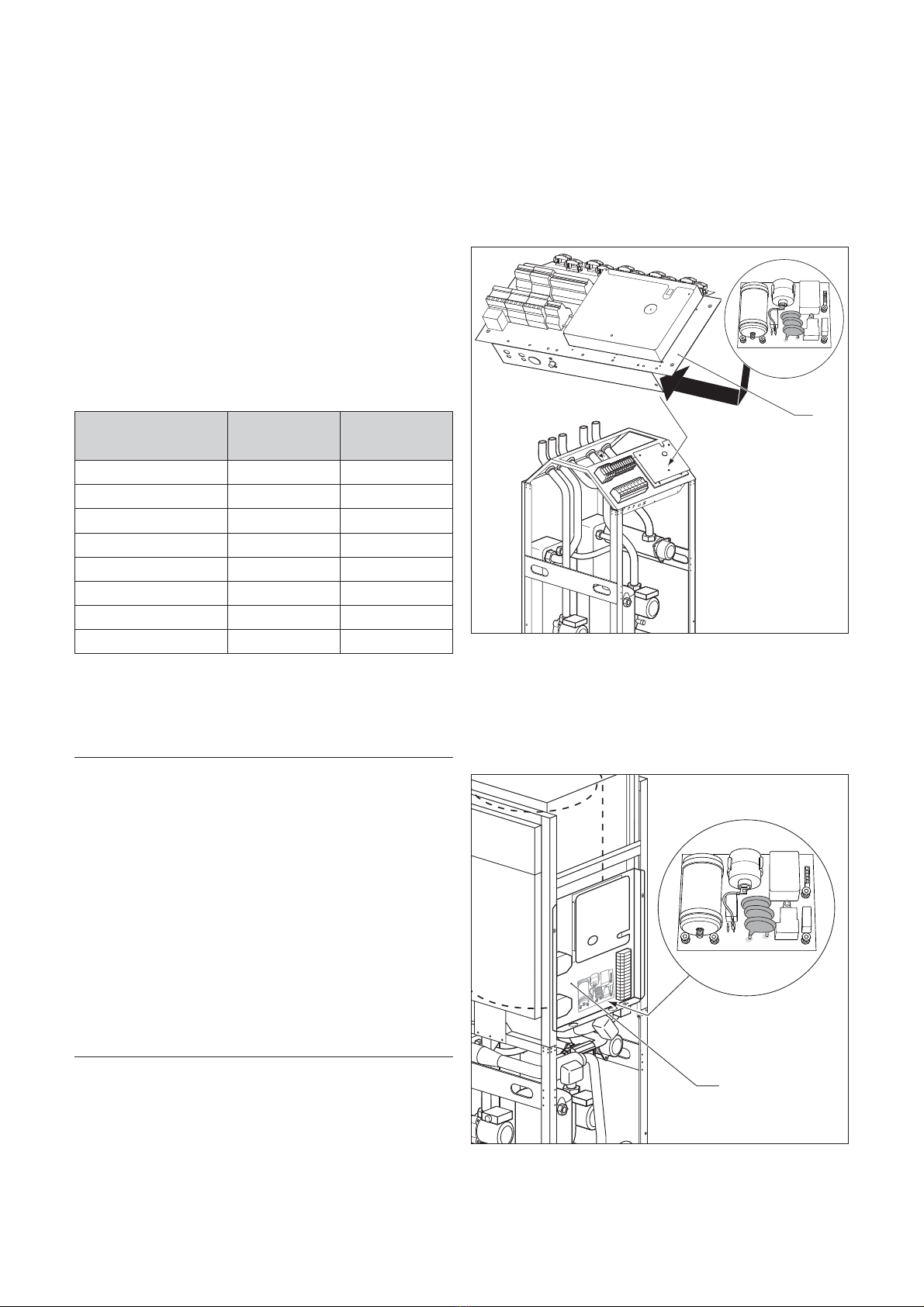
3.1 Pour VWS 61/2, 81/2, 101/2 230 V
La platine de limiteur de courant de démarrage se trouve
dans le boîtier de commande sous la plaque d‘installation
électrique (1).
1
Fig. 3.1 Lieu de montage de la platine
(pour VWS 61/2, 81/2, 101/2 230 V)
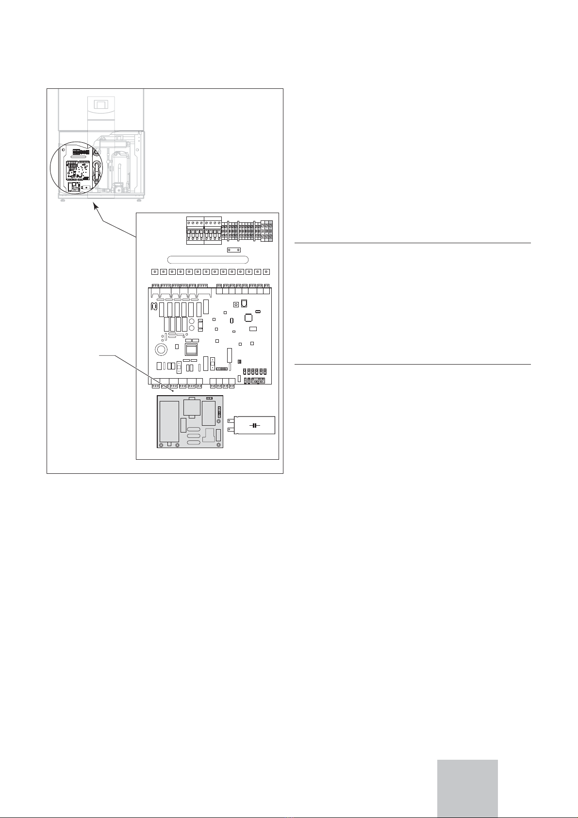
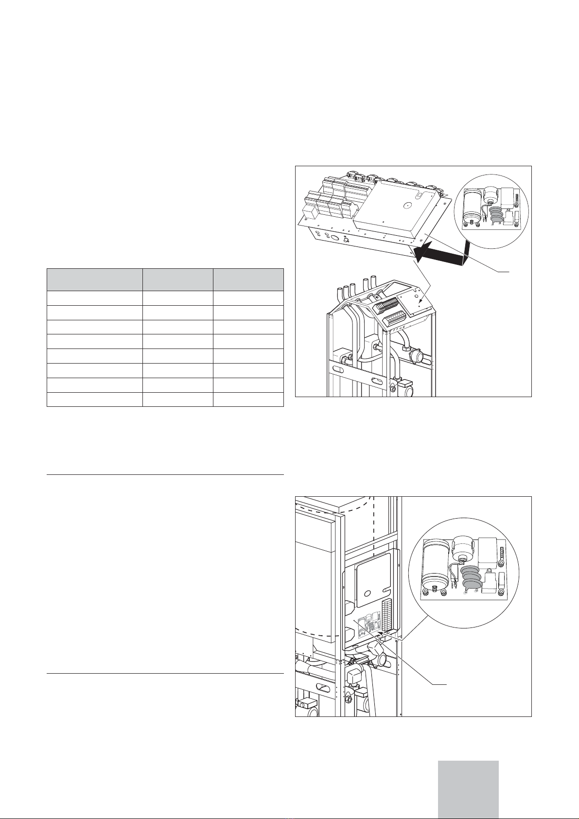
3.2
Pour VWS 63/2, 83/2, 103/2 230 V et
VWL 71, VWL 91 230 V
La platine de limiteur de courant de démarrage se trouve
dans le boîtier de commande sur la plaque d‘installation
électrique (1).
1
Fig. 3.2 Lieu de montage de la platine
(pour VWS 63/2, 83/2, 103/2 230 V)
Remarques relatives à la documentation 1
Consignes de sécurité et prescriptions 2
Lieu de montage 3
FR

10 Notice de montage - Limiteur de courant de démarrage pour VWS/VWL
4 Montage
4 Montage
4.1 Colisage
- Platine de limiteur de courant de démarrage
- Manuel d’installation (Référence 0020068997)
4.2 Raccorder le limiteur de courant de démarrage
• Retirez toutes
les lignes d‘entrée et de sortie et
debranchez toutes les fiches de la platine.
• Retirez la platine des quatre supports.
• Dans le boîtier de commande, montez la platine du li-
miteur de courant de démarrage sur la plaque
d‘installation électrique (1) en enclenchant la platine
dans les supports prévus à cet effet.
hAttention
Veillez à ce que la platine du limiteur de courant
de démarrage s‘enclenche bien dans les
supports !
• Raccordez les lignes d‘entrée et de sortie du limiteur
de courant de démarrage sur les bornes de raccorde-
ment en tenant compte des couleurs. Respectez aussi
le schéma électrique correspondant sur les premières
pages de ce manuel et la figure au chapitre 5.
aDanger!
Risque de surchauffe !
Les lignes de commande et de raccordement ne
doivent passer ni par la platine principale, ni par
la platine du limiteur de courant de démarrage.
Posez les lignes menant au limiteur de courant
de démarrage sur le côté en les faisant passer
le long des platines.
L
L
L1
L1
L2
L2
2
2
L3
L3
L1
L1
L1
L1
L2
L2
2
2
L
L3
L3
3
3
N
N
N
L
L3
L3
3
3
N
N
N
N
N
L1
L1
L1
1
1
L3
L3
L3
3
L2
L2
2
L2
2
2
A9-30-10
A12-30-10
0
Case
Case
L
L
L
L
L
L
L
L
L
L
L
L
L
L
L
L
L
L
L
L
N
N
N
N
N
N
N
N
N
N
N
N
N
N
N
N
L
L
L
N
N
N
L
L
L
N
N
N
Inject
Inject
CH1/P
CH1/P
C
230V
230V
2
Fan
Fan
PBn
PBn
Vcoo
Vcool
Vc
PSw
P Sw
P
omp
omp
Co
ICL
ICL
230V
230V
2
N
N
N
N
Auf
Auf
Zu
u
Zu
L
L
PE
P
PE
P
PE
P
PE
N
N
1
1
2
2
1
1
2
2
1
1
2
2
2
1
1
2
2
1
1
2
2
1
1
2
2
2
DC
CF
OT
AF
A
-
+
+
Auf
Auf
Zu
u
Zu
PE
PE
EP
N
N
L
L
L
PE
P
PE
ZP
N
N
L
L
L
PE
P
PE
SK2-P
P
N
N
L
L
L
PE
P
PE
HK2-P
P
HK2-P
VF2
RF
VF1
SP
BUS
S
WR
PW
R
1xZP
1xZP
UV1
L1L2 L3
Case
LLLLLLNLNNNNNNLNLN
InjectCH1/P230 VFanP BnVcoolP SwCompICL
230V
NNAufZu LPEPEN121212121212 DCFOTAF - uZfuA+PE
EP
NLPE
ZP
NLPE
SK2-P
NLPE
HK2-PHK2-PVF2RFVF1SPBUSPWR1xZP UV1
1
A9-30-10 A16-30-10
L1
L1L1 L1 N
N N
NPEPE
B B PEL1 N
Fig. 3.3 Lieu de montage de la platine
(pour VWL 71, VWL 91 230 V)

11Notice de montage - Limiteur de courant de démarrage pour VWS/VWL
Connexions électriques 5
5 Connexions électriques
4 x
1
2
3
4
567 10 9 8
Fig. 5.1 Vue d’ensemble des connexions électriques
Pour VWS ..1/2 230 V et VWS ..3/2 230 V:
No. Couleur, explication Signe sur la platine Élément dans le schéma électrique
1 gris, du bloc d’alimentation L D
2 noir/marron/gris,
fiche la ligne de commande dès la platine principale
-C
3 blue, au compresseur R A
4 blue, du bloc d’alimentation N D
5 gris, du condensateur CR B
6 noir, au contacteur du compresseur - E
7 noir, au compresseur C A
8 marron, au condensateur - B
9 marron, au compresseur - A
10 noir/noir, câble dès la platine principale ASB C
Pour VWL 71 230 V et VWL 91 230 V:
No. Couleur, explication Signe sur la platine Élément dans le schéma électrique
1 gris, dès le contacteur du compresseur L E
2 noir/marron/gris,
fiche la ligne de commande dès la platine principale
-C
3 blue, au compresseur R A
4 blue, du bloc d’alimentation N D
5 gris, du condensateur CR B
6 pas utiliser - -
7 pas utiliser - -
8 marron, au condensateur - B
9 marron, au compresseur - A
10 noir/noir, câble dès la platine principale ASB C
FR

12 Installation instructions - Inrush current limiter for VWS/VWL
1 Notes on the documentation
2 Safety instructions and regulations
3 Installation location
3.1 For VWS 61/2, 81/2, 101/2 230 V
The inrush current limiter is located under the installati-
on panel (1) in the electronics box.
1
Fig. 3.1 Installation location of the inrush current limiter
(for VWS 61/2, 81/2, 101/2 230 V)
3.2
For VWS 63/2, 83/2, 103/2 230 V and VWL 71,
VWL 91 230 V
The inrush current limiter is located on the installation
panel (1) in the electronics box.
1
Fig. 3.2 Installation location of the inrush current limiter
(for VWS 63/2, 83/2, 103/2 230 V)
1 Notes on the documentation
We accept no liability for damage caused by a failure
to observe these instructions.
Auxiliary service equipment
Installation instructions geoTHERM VWS
Instructions for use geoTHERM VWL
All manuals of accessories and control units installed in
the heating system.
Applicability of the manual
These installation instructions apply exclusively to
appliances with the following part numbers:
Appliance type Part number of
the appliance
Part number of
the accessories
VWS 61/2 230 V 0010005501 0020064070
VWS 81/2 230 V 0010005502 0020064070
VWS 101/2 230 V 0010005503 0020064070
VWS 63/2 230 V 0010005504 0020064070
VWS 83/2 230 V 0010005505 0020064070
VWS 103/2 230 V 0010005506 0020064070
VWL 71 230 V 0010005694 0020064070
VWL 91 230 V 0010005695 0020066204
Tab. 1.1: Part numbers of the appliances and the corresponding
accessories
The part number of the appliance can be found on the
identification plate.
aWarning !
To ensure all the functions of your Vaillant
appliance on a continuing basis and in order not
to change the approved original condition, only
original Vaillant replacement parts may be used
for service and maintenance work!
Information can be obtained from Vaillant
Customer Service Centres.
2
Safety instructions and regulations
The inrush current limiter may only be installed by a
competent qualified person registered with Corgi.
To ensure the safe installation of your appliance, the
laws, regulations, technical rules and standards
pertaining to the installation must be considered and
adhered to.
eDanger !
Danger of death from electric shock! The supply
terminals in the terminal box of the device are
under voltage even if the mains switch is off.
Before working on the appliance, turn off the
power supply

13Installation instructions - Inrush current limiter for VWS/VWL
L
L
L1
L1
L2
L2
2
2
L3
L3
L1
L1
L1
L1
L2
L2
2
2
L
L3
L3
3
3
N
N
N
L
L3
L3
3
3
N
N
N
N
N
L1
L1
L1
1
1
L3
L3
L3
3
L2
L2
2
L2
2
2
A9-30-10
A12-30-10
0
Case
Case
L
L
L
L
L
L
L
L
L
L
L
L
L
L
L
L
L
L
L
L
N
N
N
N
N
N
N
N
N
N
N
N
N
N
N
N
L
L
L
N
N
N
L
L
L
N
N
N
Inject
Inject
CH1/P
CH1/P
C
230V
230V
2
Fan
Fan
PBn
PBn
Vcoo
Vcool
Vc
PSw
P Sw
P
omp
omp
Co
ICL
ICL
230V
230V
2
N
N
N
N
Auf
Auf
Zu
u
Zu
L
L
PE
P
PE
P
PE
P
PE
N
N
1
1
2
2
1
1
2
2
1
1
2
2
2
1
1
2
2
1
1
2
2
1
1
2
2
2
DC
CF
OT
AF
A
-
+
+
Auf
Auf
Zu
u
Zu
PE
PE
EP
N
N
L
L
L
PE
P
PE
ZP
N
N
L
L
L
PE
P
PE
SK2-P
P
N
N
L
L
L
PE
P
PE
HK2-P
P
HK2-P
VF2
RF
VF1
SP
BUS
S
WR
PW
R
1xZP
1xZP
UV1
L1L2 L3
Case
LLLLLLNLNNNNNNLNLN
InjectCH1/P230 VFanP BnVcoolP SwCompICL
230V
NNAufZu LPEPEN121212121212 DCFOTAF - uZfuA+PE
EP
NLPE
ZP
NLPE
SK2-P
NLPE
HK2-PHK2-PVF2RFVF1SPBUSPWR1xZP UV1
1
A9-30-10 A16-30-10
L1
L1L1 L1 N
N N
NPEPE
B B PEL1 N
Fig. 3.3 Installation location of the inrush current limiter
(for VWL 71, VWL 91 230 V)
4 Assembly
4.1 Scope of delivery
- Inrush current limiter
- Maunal (Art.-Nr. 0020068997)
4.2 Connecting the inrush current limiter
• Unfasten all incoming and outgoing connections and
unplug all connectors on the inrush current limiter.
• Withdraw the printed circuit board form the four
fasteners.
• Install the new printed circuit board of the inrush
current limiter onto the installation panel (1) in the
electronics box by clicking the printed circuit board on
the fasteners.
hHint
Ensure that the printed circuit board of the
inrush current limiter is tightly engage in the
fasteners!
• Connect all incoming and outgoing connections to the
inrush current limiter respecting colours of the
electrical contacts.
Pay attention to the corresponding wiring diagram on
the first pages of this manual and the figure in chapter 5.
aWarning!
Risk of overheating!
The control and wiring cables must not be laid
over the inrush current limiter or the
mainboard. Install the cables laterally to these
printed circuit boards.
Assembly 4
GB

14 Installation instructions - Inrush current limiter for VWS/VWL
5 Electrical connection
4 x
1
2
3
4
567 10 9 8
Fig. 5.1 Overview of the electrical connections
For VWS ..1/2 230 V and VWS ..3/2 230 V:
No. Colour, explanation Marking on circuit board Component on wiring diagram
1 gray, from main terminal clamp L D
2black/brown/gray,
plug of the der control cable from mainboard
-C
3 blue, to compressor R A
4 blue, from main terminal clamp N D
5 gray, to condenser CR B
6 black, to compressor contactor - E
7 black, to compressor C A
8 brown, to condenser - B
9 brown, to compressor - A
10 black/black, cable from the mainboard ASB C
Für VWL 71 230 V and VWL 91 230 V:
No. Colour, explanation Marking on circuit board Component on wiring diagram
1 gray, from compressor contactor L E
2black/brown/gray,
plug of the der control cable from mainboard
-C
3 blue, to compressor R A
4 blue, from main terminal clamp N D
5 gray, to condenser CR B
6 Not used - E
7 Not used C A
8 brown, to condenser - B
9 brown, to compressor - A
10 black/black, cable from the mainboard ASB C

15Montageanleitung - Anlaufstrombegrenzer für VWS/VWL
1 Indicazioni riguardo alla documentazione
2 Indicazioni di sicurezza e norme
3 Luogo di montaggio
1 Indicazioni riguardo alla documenta-
zione
Non assumiamo la responsabilità per danni che ven-
gono causati dall’inosservanza di questo manuale.
Documenti validi in più
Manuale d‘installazione geoTHERM VWS
Manuale d‘uso geoTHERM VWL
All’occorrenza valgono anche i manuali di tutti gli acces-
sori e regolatori usati.
Validità del manuale
Questo manuale di montaggio vale esclusivamente per
gli apparecchi con i seguenti numeri di articolo.
Tipo Num. articolo
dell‘apparecchio
Num. art. del li-
mitatore di corr.
di avviamento
VWS 61/2 230 V 0010005501 0020064070
VWS 81/2 230 V 0010005502 0020064070
VWS 101/2 230 V 0010005503 0020064070
VWS 63/2 230 V 0010005504 0020064070
VWS 83/2 230 V 0010005505 0020064070
VWS 103/2 230 V 0010005506 0020064070
VWL 71 230 V 0010005694 0020064070
VWL 91 230 V 0010005695 0020066204
Tab. 1.1: Num. articolo dell’apparecchio e dei limitatori di
corrente di avviamanto utilizzabili
Il numero dell’articolo dell’aparecchio è riportato sulla
targhetta indicatrice del tipo.
aAttenzione!
Per garantire a lungo andare tutte le funzioni
dell‘apparecchio Vaillant e per non modificare lo
stato di serie ammesso sono permessi solo
pezzi di ricambio originali di Vaillant durante I
lavori di manutenzione e di riparazione! Per ot-
tenere informazioni, rivolgetevi ad un ufficio per
clienti Vaillant.
2 Indicazioni di sicurezza e norme
Il limitatore di corrente di avviamento deve essere instal-
lato da uno specialista autorizzato che è responsabile
per l’osservanza delle norme e delle disposizioni in vi-
gore.
ePericolo!
Pericolo di una scossa di corrente! Spegnete
sempre tutte le alimentazioni di corrente prima
di effettuare lavori di installazione elettriche.
Assicuratevi che esse sono protette contro un
riavviamento non intenzionale.
3 Luogo del montaggio
3.1 Per VWS 61/2, 81/2, 101/2 230 V
Il limitatore di corrente di avviamento si trova sotto la
cassetta degli interruttori (1) su una lamiera di installazi-
one elettrica.
1
Imm. 3.1 Luogo di montaggio del limitatore di corrente di
avviamento (per VWS 61/2, 81/2, 101/2 230 V)
3.2
Per VWS 63/2, 83/2, 103/2 230 V und
VWL 71, VWL 91 230 V
Il limitatore di corrente di avviamento si trova nella cassetta
degli interruttori sulla lamiera di installazione elettrica (1).
1
Imm. 3.2 Luogo di montaggio del limitatore di corrente di
avviamento (per VWS 63/2, 83/2, 103/2 230 V)
IT

Montageanleitung - Anlaufstrombegrenzer für VWS/VWL16
Montaggio 4
L
L
L1
L1
L2
L2
2
2
L3
L3
L1
L1
L1
L1
L2
L2
2
2
L
L3
L3
3
3
N
N
N
L
L3
L3
3
3
N
N
N
N
N
L1
L1
L1
1
1
L3
L3
L3
3
L2
L2
2
L2
2
2
A9-30-10
A12-30-10
0
Case
Case
L
L
L
L
L
L
L
L
L
L
L
L
L
L
L
L
L
L
L
L
N
N
N
N
N
N
N
N
N
N
N
N
N
N
N
N
L
L
L
N
N
N
L
L
L
N
N
N
Inject
Inject
CH1/P
CH1/P
C
230V
230V
2
Fan
Fan
PBn
PBn
Vcoo
Vcool
Vc
PSw
P Sw
P
omp
omp
Co
ICL
ICL
230V
230V
2
N
N
N
N
Auf
Auf
Zu
u
Zu
L
L
PE
P
PE
P
PE
P
PE
N
N
1
1
2
2
1
1
2
2
1
1
2
2
2
1
1
2
2
1
1
2
2
1
1
2
2
2
DC
CF
OT
AF
A
-
+
+
Auf
Auf
Zu
u
Zu
PE
PE
EP
N
N
L
L
L
PE
P
PE
ZP
N
N
L
L
L
PE
P
PE
SK2-P
P
N
N
L
L
L
PE
P
PE
HK2-P
P
HK2-P
VF2
RF
VF1
SP
BUS
S
WR
PW
R
1xZP
1xZP
UV1
L1L2 L3
Case
LLLLLLNLNNNNNNLNLN
InjectCH1/P230 VFanP BnVcoolP SwCompICL
230V
NNAufZu LPEPEN121212121212 DCFOTAF - uZfuA+PE
EP
NLPE
ZP
NLPE
SK2-P
NLPE
HK2-PHK2-PVF2RFVF1SPBUSPWR1xZP UV1
1
A9-30-10 A16-30-10
L1
L1L1 L1 N
N N
NPEPE
B B PEL1 N
Imm. 3.3 Luogo di montaggio per il limitatore di corrente di
avviamento (per VWL 71, VWL 91 230 V
4 Montaggio
4.1 Entità di consegna:
- Limitatore di corrente di avviamento
- Manuale di montaggio (Nr. art. 0020068997)
4.2
Collegare il limitatore di corrente di avviamento
• Staccate tutti i collegamenti di entrata e di uscita e
staccate tutte le spine dal limitatore di corrente di av-
viamento.
• Tirate la piastrina dai 4 supporti.
• Montate la piastrina del limitatore di corrente di avvia-
mento sulla lamiera di installazione elettrica (1) aggan-
ciando la piastrina nei supporti presenti.
hIndicazione
Assicuratevi che la piastrina del limitatore di
corrente di avviamento sia agganciata in modo
corretto nei supporti!
• Collegate i collegamenti di entrata e di uscita del limi-
tatore di corrente di avviamento al limitatore di cor-
rente di avviamento rispettando i colori corretti. Os-
servate lo schema di cavetteria corrispondente ripor-
tato sulle prime pagine di questo manuale e
l’immagine in capitolo 5.
aAttenzione!
Pericolo di surriscaldamento!
Le linee di comando e di collegamento non
devono né essere condotte sopra la piastrina
principale, né sopra la piastrina del limitatore di
corrente di avviamento. Posate le linee verso il
limitatore di corrente di avviamento
lateralmente lungo le piastrine.

17Montageanleitung - Anlaufstrombegrenzer für VWS/VWL
Collegamento elettrico 5
5 Collegamento elettrico
4 x
1
2
3
4
567 10 9 8
Imm. 5.1 Visione d’insieme dei collegamenti elettrici
Per VWS ..1/2 230V e VWS ..3/2 230 V:
Nr. Colore, spiegazione Marcatura sulla piastrina Elemento, schema cavetteria
1 grigio, dal morsetto principale L D
2 nero/marrone/grigio,
spina del circuito di controllo dalla piastrina principale
-C
3 blu, verso il compressore R A
4 blu, dal morsetto principale N D
5 grigio, verso il condensatore d‘esercizio CR B
6 nero, verso il relè del compressore - E
7 nero, verso il compressore C A
8 marrone, verso il condensatore d‘esercizio - B
9 marrone, verso il compressore - A
10 nero/nero, collegamento dalla piastrina principale ASB C
Per VWL 71 230 V e VWL 91 230 V:
Nr. Colore, spiegazione Marcatura sulla piastrina Elemento, schema cavetteria
1 grigio, dal relè del compressore L E
2 nero/marrone/grigio,
spina del circuito di controllo dalla piastrina principale
-C
3 blu, verso il compressore R A
4 blu, dal morsetto principale N D
5 grigio, verso il condensatore d‘esercizio CR B
6 non occupato - -
7 non occupato - -
8 marrone, verso il condensatore d‘esercizio - B
9 marrone, verso il compressore - A
10 nero/nero, collegamento dalla piastrina principale ASB C
IT

Montageanleitung - Anlaufstrombegrenzer für VWS/VWL18
1 Henvisninger om veiledningene
2 Sikkerhetshenvisninger og forskrifter
3 Monteringssted
1 Henvisninger om veiledningene
Vi overtar intet ansvar for skader som oppstår fordi
disse veiledningene ikke følges.
Supplerende dokumenter
Installasjonsveiledning geoTHERM VWS
Bruksveiledning geoTHERM VWL
Eventuelt gjelder også ytterligere veiledninger for alt til-
behør og regulatorer som brukes.
Veiledningens gyldighet
Denne monteringsveiledningen gjelder utelukkende for
apparater med følgende artikkelnummer.
Type Apparatets
artikkelnummer
Startstrømbe-
grenserens
artikkelnummer
VWS 61/2 230 V 0010005501 0020064070
VWS 81/2 230 V 0010005502 0020064070
VWS 101/2 230 V 0010005503 0020064070
VWS 63/2 230 V 0010005504 0020064070
VWS 83/2 230 V 0010005505 0020064070
VWS 103/2 230 V 0010005506 0020064070
VWL 71 230 V 0010005694 0020064070
VWL 91 230 V 0010005695 0020066204
Tab. 1.1: Apparatenes artikkelnummer og de
startstrømbegrensere som kan brukes
Apparatets artikkelnummer er angitt på typeskiltet.
aObs!
For å sikre alle funksjoner på Vaillant-apparatet
over tid og for at den godkjente serietilstanden
ikke skal endres, må det kun brukes originale
reservedeler fra Vaillant ved vedlikeholds- og
reparasjonsarbeider! Opplysninger får du hos
alle Vaillant kundeservicesteder.
2
Sikkerhetshenvisninger og forskrifter
Startstrømbegrenseren må installeres av en autorisert
håndverker, som er ansvarlig for at de respektive stan-
darder og forskrifter overholdes.
eFare!
Fare for strømstøt! Strømtilførselen må alltid
kobles ut før installasjonsarbeider på det elek-
triske anlegget gjennomføres. Kontroller at
strømtilførselen er sikret mot utilsiktet gje-
ninnkobling.
3 Monteringssted
3.1 For VWS 61/2, 81/2, 101/2 230 V
Startstrømbegrenseren befinner seg under bryterboksen
(1) på en installasjonsplate.
1
Fig. 3.1 Monteringssted for startstrømbegrenseren
(for VWS 61/2, 81/2, 101/2 230 V)
3.2
For VWS 63/2, 83/2, 103/2 230 V og
VWL 71, VWL 91 230 V
Startstrømbegrenseren befinner seg i bryterboksen på
installasjonsplaten (1).
1
Fig. 3.2 For VWS 63/2, 83/2, 103/2 230 V og
VWL 71, VWL 91 230 V

19Montageanleitung - Anlaufstrombegrenzer für VWS/VWL
Montering 4
L
L
L1
L1
L2
L2
2
2
L3
L3
L1
L1
L1
L1
L2
L2
2
2
L
L3
L3
3
3
N
N
N
L
L3
L3
3
3
N
N
N
N
N
L1
L1
L1
1
1
L3
L3
L3
3
L2
L2
2
L2
2
2
A9-30-10
A12-30-10
0
Case
Case
L
L
L
L
L
L
L
L
L
L
L
L
L
L
L
L
L
L
L
L
N
N
N
N
N
N
N
N
N
N
N
N
N
N
N
N
L
L
L
N
N
N
L
L
L
N
N
N
Inject
Inject
CH1/P
CH1/P
C
230V
230V
2
Fan
Fan
PBn
PBn
Vcoo
Vcool
Vc
PSw
P Sw
P
omp
omp
Co
ICL
ICL
230V
230V
2
N
N
N
N
Auf
Auf
Zu
u
Zu
L
L
PE
P
PE
P
PE
P
PE
N
N
1
1
2
2
1
1
2
2
1
1
2
2
2
1
1
2
2
1
1
2
2
1
1
2
2
2
DC
CF
OT
AF
A
-
+
+
Auf
Auf
Zu
u
Zu
PE
PE
EP
N
N
L
L
L
PE
P
PE
ZP
N
N
L
L
L
PE
P
PE
SK2-P
P
N
N
L
L
L
PE
P
PE
HK2-P
P
HK2-P
VF2
RF
VF1
SP
BUS
S
WR
PW
R
1xZP
1xZP
UV1
L1L2 L3
Case
LLLLLLNLNNNNNNLNLN
InjectCH1/P230 VFanP BnVcoolP SwCompICL
230V
NNAufZu LPEPEN121212121212 DCFOTAF - uZfuA+PE
EP
NLPE
ZP
NLPE
SK2-P
NLPE
HK2-PHK2-PVF2RFVF1SPBUSPWR1xZP UV1
1
A9-30-10 A16-30-10
L1
L1L1 L1 N
N N
NPEPE
B B PEL1 N
Fig. 3.3 Monteringssted for startstrømbegrenseren
(for VWL 71, VWL 91 230 V)
4 Montering
4.1 Leveringsomfang:
- Startstrømbegrenser
- Monteringsveiledning (art.-nr. 0020068997)
4.2 Koble til startstrømbegrenser
• Løsne alle inn- og utgangsledninger og trekk alle
støpsler av startstrømbegrenseren.
• Trekk kretskortet av de 4 holderne.
• Monter kretskortet for startstrømbegrenseren på in-
stallasjonsplaten (1) ved å klipse kortet inn i holderne.
hMerk
Pass på at kortet for startstrømbegrenseren
smekker riktig inn i holderne!
• Koble inn- og utgangsledningene for startstrømbe-
grenseren med riktig farge til startstrømbegrenseren.
Følg det tilsvarende koblingsskjemaet på de første si-
dene i denne veiledningen og bildet i kapittel 5.
aObs!
Fare for overoppheting!
Styre- og tilkoblingsledningene må ikke føres
over hovedkretskortet eller over kretskortet for
startstrømbegrenseren. Legg ledningene til
startstrømbegrenseren på siden langs kortene.
NO

Montageanleitung - Anlaufstrombegrenzer für VWS/VWL20
5 Elektrisk tilkobling
4 x
1
2
3
4
567 10 9 8
Fig. 5.1 Oversikt over elektriske tilkoblinger
For VWS ..1/2 230V og VWS ..3/2 230 V:
Nr. Farge, forklaring Markering på kretskortet Komponent, koblingsskjema
1 grå, fra hovedtilkoblingsklemme L D
2 sort/brun/grå,
støpsel for styreledningen fra hovedkretskortet
-C
3 blå, til kompressor R A
4 blå, fra hovedtilkoblingsklemme N D
5 grå, til driftskondensator CR B
6 sort, til kompressorkontaktor - E
7 sort, til kompressor C A
8 brun, til driftskondensator - B
9 brun, til kompressor - A
10 sort/sort, ledning fra hovedkretskort ASB C
For VWL 71 230 V og VWL 91 230 V:
Nr. Farge, forklaring Markering på kretskortet Komponent, koblingsskjema
1 grå, fra kompressorkontaktor L E
2 sort/brun/grå,
støpsel for styreledningen fra hovedkretskortet
-C
3 blå, til kompressor R A
4 blå, fra hovedtilkoblingsklemme N D
5 grå, til driftskondensator CR B
6 ikke i bruk - -
7 ikke i bruk - -
8 brun, til driftskondensator - B
9 brun, til kompressor - A
10 sort/sort, ledning fra hovedkretskort ASB C
This manual suits for next models
15
Table of contents
Languages:
Other Vaillant Heat Pump Accessories manuals