4 Operating
8Instructions for use VRC 470 0020116689_01
3.4.2 Hot water generation
You can use the controller to set the temperature and time
for the hot water generation. The heat generator heats the
water in the domestic hot water cylinder until it reaches the
set temperature. You can set a time period during which hot
water should be available in the domestic hot water cylinder.
3.4.3 Circulation
If a circulation pump is installed in the heating installation,
you can set a period for circulation. During the set period, hot
water circulates from the domestic hot water cylinder to the
water taps and back to the domestic hot water cylinder. If, for
example, you turn on a water tap during this time, hot water
will come out of the tap immediately.
3.5 Frost protection function
The frost protection function protects the heating system and
apartment from frost damage. The frost protection function
monitors the outside temperature.
If the outside temperature
–falls below 3 °C, the controller switches the heater on
after a frost protection delay time, and brings the target
room temperature to 5 °C.
–rises above 4 °C, the controller does not switch the
heater on but monitors the outside temperature.
Note
Your competent person will set the frost protection
delay time during the installation.
3.5.1 Enhanced frost protection function
If the heat pump is connected and you have activated the
Cooling operating mode, the additional enhanced frost pro-
tection function is also available.
–If the outside temperature falls below 4 °C for longer than
10 minutes, the controller switches off the Cooling oper-
ating mode.
4 Operating
4.1 Operating structure
4.1.1 Access level for the operator
Through the access level for the operator, you access im-
portant information and set-up options which do not require
any special prior knowledge. Via a menu structure, you can
access configurable or read-only values.
4.1.2 Access level for the skilled tradesman
The skilled tradesman will set further values for the heating
installation via the access level for the skilled tradesman.
The settings may only be made by someone with specialist
knowledge; this level is therefore code-protected.
4.1.3 Menu structure design
The menu structure of the controller is split into four levels.
There are three selection levels and one setting level. From
the basic display, you access selection level 1 and, from
there, you can access the menu structure for one level up or
down. The setting level is accessed from the lowest selection
level.
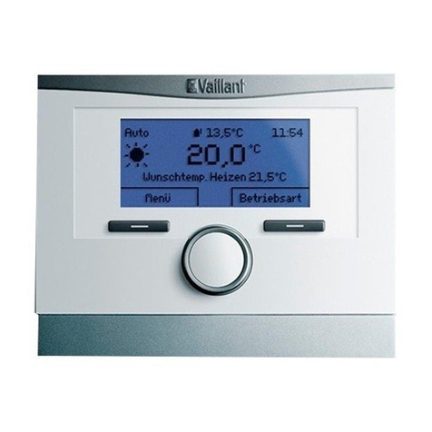
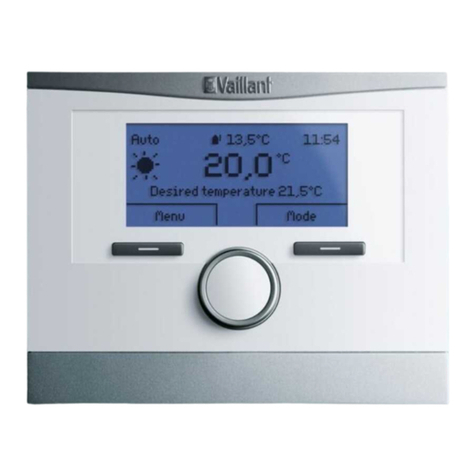
4.1.4 Basic display
Auto 5,0°C
°C
19,5
15:34
Desired heating temp. 20,0°C
Menu Op. mode
1
3
4
5
9
8
6
7
2
1 Symbol for the current
outside temperature
2 Current outside temperat-
ure
3 Current room temperature
4 Time
5 Current function of the
right-hand selection button
6 Current function of the left-
hand selection button
7 Desired setting (e.g. de-
sired heating temp.)
8 Symbol for Auto operating
mode
9 Operating mode set
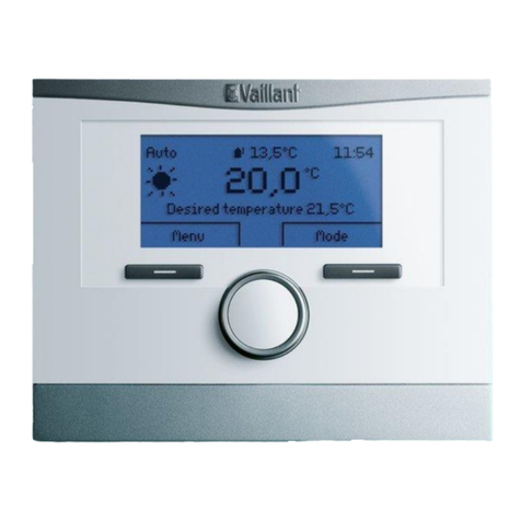
The basic display shows the current settings and values of
the heating installation. If you make a setting on the control-
ler, the display on the screen switches from the basic display
to the display with the new setting.
The basic display appears when you:
–press the left-hand selection button and thus exit selec-
tion level 1.
–do not operate the controller for more than 5 minutes.
The basic display shows the key displays heating, cooling
and ventilation and the corresponding operating modes as
well as the status of the time period.
If your heating installation has two independent heating cir-
cuits, the competent person will determine during installation
whether or not the basic display shows the values of HEAT-
ING 1 or HEATING 2.
