Head Office:
VAISALA Oy
PL 26, FIN-00421 Helsinki
FINLAND
Phone (int.): (+358 0) 894 91
Telefax: (+358 0) 894 9227
Telex: 122832 vsala fi
ISO 9001
CERTIFIED
QUALITY
SYSTEM
TECHNICAL DATA
Sensor/Transducer type Optical code disc
Measuring range 0 ... 360°
Starting threshold < 0.4 m/s
Resolution 5.6°
Damping Ratio 0.14
Overshoot Ratio 0.65
Delay Distance 0.4 m
Accuracy better than ± 3°
Input power supply 9.5 ... 15.5 VDC, 20 mA typical
Heating power supply 20 VDC or VAC, 500 mA typical
Output 6-bit parallel GRAY code 1)
Transducer output level
(Iout < +5 mA) High state > Uin 1.5 V
(Iout > 5 mA) Low state < 1.5 V
Settling time after power turn-on < 100 µs
Electrical connections MIL-C-26482 type; 10-wire cable
Operating temperature 50 ... +55 °C (with shaft heating)
Storage temperature 60 ... +70 °C
Material
Housing AlMgSi, grey anodized
Vane AlSi12, anodized
Dimensions & Weight 300 (h) × 90 (Ø) mm; 660 g
Swept radius of vane: 172 mm
MAINTENANCE AND REPAIR
Ball bearings must be checked once a year visually and by rotating
the sensor shaft. To do this, remove the vane assembly. To ensure
proper operation, the shaft should spin smoothly and it should not
create any detectable noise.
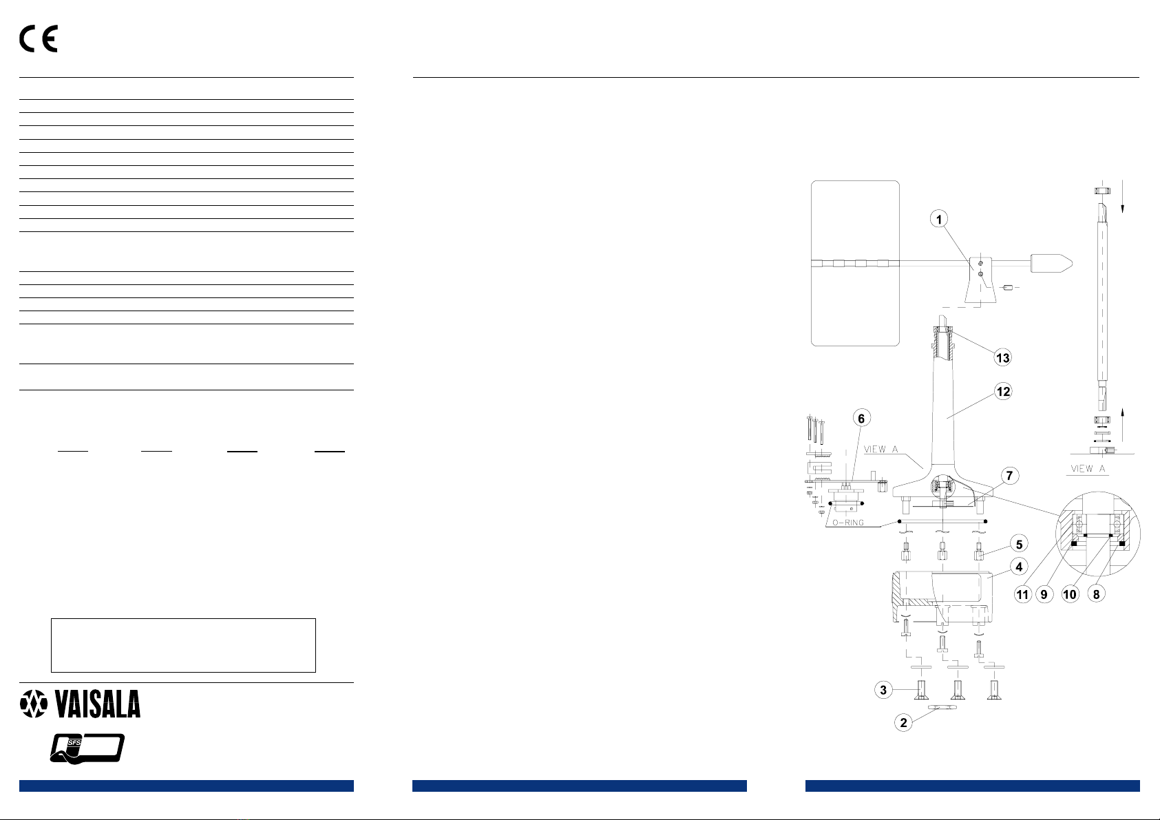
To replace the ball bearings
1Remove the vane assembly.
There are three screws at the vane assembly center. Do not
loosen the glue filled screw at the far side. The lockscrew
for the vane assembly is the lower one shown in figure 4.
2Loosen the hex nut of the connector (with 27 mm tool).
Caution: Bending may break the connector pins!
3Loosen the three pan head screws at the bottom of the sen-
sor body (with 7 mm tool).
4Remove the lower body assembly by pulling it straight out-
wards.
5Loosen the spacer screws and the heating element outlet.
6Remove the printed circuit board. Do not twist nor bend
the connector; bending may break pins.
7Loosen the code disc fixing screw and remove the disc.
8Remove the retaining ring (using narrow-pointed pliers).
9Remove the spacer ring.
10 Remove the external retaining ring at the shaft (using
narrow-pointed pliers).
11 Remove the lower bearing.
12 Push out the shaft through the upper body.
13 Remove the top bearing.
Be careful when handling the ball bearings.
Reverse work order for assembling the sensor.
The disc must be positioned so that it does not touch the opto-
coupler at any rotary position of the shaft.
When placing the lower body assembly, make sure that the O-
ring is correctly positioned between the upper and lower bodies.
It is recommended to replace the O-ring by a new one before re-
assembly.
The heating resistance element cannot be removed without special
tools. It is recommended that replacing of the heating element is
carried out by the manufacturer.
The wind vane has been counterbalanced at the factory but can be
readjusted, if necessary. To do this, loosen the vane assembly and
place it on its side on the table. A correctly balanced vane will stay
in horizontal position.
Spare parts: Order number:
Wind tail 6386WA
Set of bearings & gasket 16644WA
1) Output from connector pins C...H:
(°) Output (°) Output
CDEFGH CDEFGH
N 0 000000 E 90 011000
6 000001 96 011001
11 000011 101 011011
17 000010 107 011010
23 000110 113 011110
28 000111 118 011111
34 000101 124 011101
39 000100 129 011100
45 001100 135 010100
51 001101 141 010101
56 001111 146 010111
62 001110 152 010110
68 001010 158 010010
73 001011 163 010011
79 001001 169 010001
84 001000 174 010000
(°) Output (°) Output
CDEFGH CDEFGH
S 180 110000 W 270 101000
186 110001 276 101001
191 110011 281 101011
197 110010 287 101010
203 110110 293 101110
208 110111 298 101111
214 110101 304 101101
219 110100 309 101100
225 111100 315 100100
231 111101 321 100101
236 111111 326 100111
242 111110 332 100110
248 111010 338 100010
253 111011 343 100011
259 111001 349 100001
264 111000 354 100000
Figure 4. WAV151 assembly
Ref. WAV151-U185en-1.1


