manuals.online logo
Brands
  1. Home
  2. •
  3. Brands
  4. •
  5. Vaisala
  6. •
  7. Transmitter
  8. •
  9. Vaisala PDT102 User manual

Vaisala PDT102 User manual

Vaisala Differential Pressure Transmitter
PDT102
M211285EN-F___________________________________________________________________________________ 1
Die deutschsprachige Version kann von www.vaisala.com/PDT102
heruntergeladen werden.
Vous pouvez télécharger la version française sur www.vaisala.com/PDT102.
日本語版は www.vaisala.com/PDT102 からダウンロードできます。
您可以访问 www.vaisala.com/PDT102 下载简体中文翻译。
WARNING - READ BEFORE INSTALLATION
Vaisala Differential Pressure Transmitter PDT102 is a high-performance
instrument designed primarily for use in life science and cleanroom
applications. PDT102 is not authorized for use as a critical component in life
support devices or systems. Consult Vaisala before installing if there are any
questions or concerns.
Overpressure: Pressure spikes in excess of the rated overpressure capability
of the transmitter may cause irreversible electrical and/or mechanical damage
to the transmitter.
Static electrical charges: To avoid damage to the transmitter the
operator/installer should follow proper ESD (electrostatic discharge)
protection procedures.
TECHNICAL SPECIFICATION
Performance
Measurement range (bidirectional)
±50 Pa or
±0.25 in H
2O
Overpressure
Proof pressure
0.7 bar
Burst pressure
1.7 bar
Static pressure
1.7 bar
Pressure type
Differential, gauge, vacuum and compound
Accuracy
(incl. non-linearity, hysteresis,
repeatability and zero/span
calibration settings)
0.25 % span
or 0.5 % span,
depending on choice
Repeatability
for 0.25 % span accuracy
0.03 %
for 0.5 % span accuracy
0.05 %
Electrical resolution
1 x 10⁻⁴ span
Long-term stability
≤0.5 % span/year
Response time (10...90 %)
250 ms
Warm-up time
15 s
Compensated temperature range
+2...+57 °C
(+35.6...+134.6 °F)
Temperature dependence
±(0.036 Pa + 0.036 % of reading)/°C
or
±(0.0001 inH2
O + 0.02% of reading)/°F
(reference 21 °C or 70 °F)
Mounting position error (zero adjustable)
≤0.25 %
Adjustments (front accessible)
Zero (span low)
±5 % span
Span (span high)
±3 % span
Operating environment
Operating temperature
-29...+70 °C (-20.2...+158 °F)
Storage temperature
-40...+82 °C (-40...+179.6 °F)
Electromagnetic compatibility
EN61326-1, Basic immunity
test requirements
Note: If used in an electromagnetic field of 3 V/m, with narrow frequency area
of 80
- 120 Mhz, it is possible that the current output of PDT102 can deviate
max. 0.3 % (with accuracy specified 0.25%).
Inputs and outputs
Process connection
1/8 NPT female according to ANSI/ASME B1.20.1
Output signal
2-wire
4...20 mA
3-wire
0...5 V
Operating voltage
12...36 VDC
Max. loop resistance for 4...20 mA
≤(Supply voltage - 12V)/0.022 A
Supply current
for 0...5 V output
max. 10 mA
for 4...20 mA output
max. 20 mA
Electrical connection
Screw terminals, 12...22 AWG (0.33 up to 3.31 mm2)
Mechanics
Medium (measured gas)
Clean and dry air, non-conducting and
non-corrosive gases
Material
Process connection
Brass
Sensor element
Silicon, aluminum, glass
Case
Polycarbonate, glass filled (UL94-V-1)
Mounting
DIN rail EN 50022, EN 50035 and EN 50045
Housing classification
IP30
Weight
0.16 kg
MOUNTING
When securing to EN50022 rail first hook the top portion of the rear clip onto
the top of the rail and push gently into place. To remove, simply place finger
behind lower rear lever and pull forward. To remove from the EN50035 rail,
grasp the unit, push up, and rotate the bottom out. For the EN50045, pull
down and rotate the bottom out.
Multiple units can be stacked across the rail. Internal circuitry is vented
through the bottom of each unit. Tag holes are fabricated into the lower rear
lever and the housing below the terminal strip for calibration reference tagging
and/or ID location.
125.99
Span
Zero
V+ V– Out
22.6
99.6
80.8
Figure 1 Dimensions (in mm)
134.4
Span
Zero
V+ V– Out
22.6
99.6
80.8
Test:
+
-
Figure 2 Dimensions with Process Valve Actuator and
Test Jacks (in mm)
Quick Guide ______________________________________________________________________________ PDT102
© Vaisala 2015. All rights reserved. __________________________________________________________________ 2
ELECTRICAL WIRING
PDT102 with voltage output operates on any supply voltage between
12...36 VDC drawing less than 10 mA (24 VDC typical).
Use of a shielded cable, with the shield grounded, is required. Do not connect
the shield to the transmitter. Maximum cable length for voltage output wiring
is 30 m (98.4 ft).
+
–
+
–
POWER
SUPP
LY
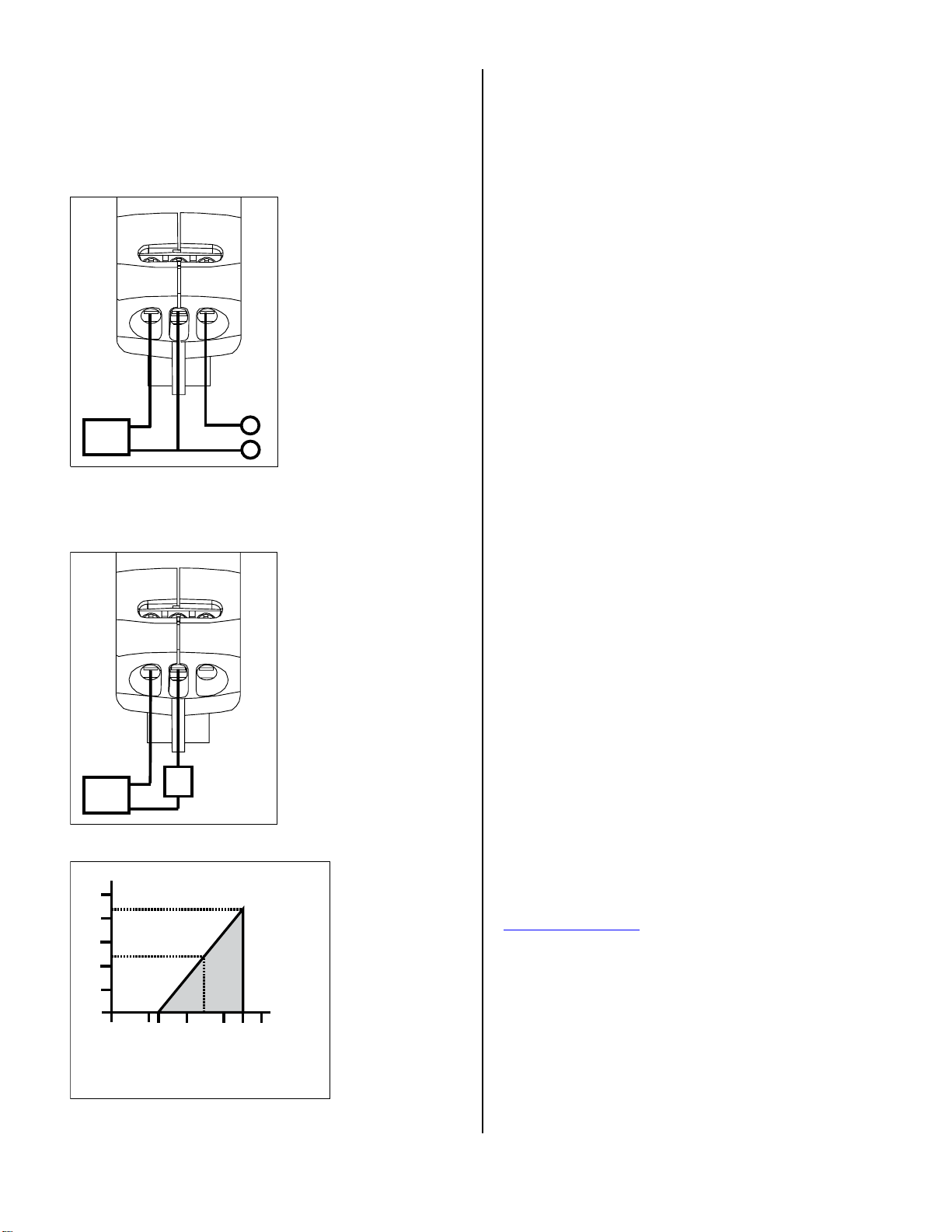
Figure 3 Voltage Output Wiring
The voltage required for a 4...20 mA output is dependent on the loop
resistance of the circuit. Refer to Figure 5 showing the minimum supply
voltage (Vmin) required for a given Loop Resistance (RL).
+
–
R
S
POWER
SUPP
LY
Figure 4 Current Output Wiring
010 12 20 30 36 40
1250
1091
1000
750
500
250
0
545
24
Loop Resistance (Ω)
Supply
Voltage (V)
Vmin = 34V+ [0244A*(R L)]
*includes a 10% safety factor
RL = RS + RW
RL = Loop Resistance (ohms)
RS = Sense Resistance (ohms)
RW = Wire Resistance (ohms)
Figure 5 Load Limitations
FRONT ACCESS TEST JACKS (OPTION)
The front access test jacks provide on-line process reference signal or
calibration signal without disconnecting power supply wiring. Measurements
can be made using a standard multimeter. Reference signals through the test
jacks are made in series for 4...20 mA output and in parallel for voltage
output.
Gold plated contacts accept standard 0.08˝ microtip test leads, snapping in
place for secure measurements.
PROCESS VALVE ACTUATOR (OPTION)
The process valve actuator option includes the process valve actuator,
actuator tool, and 7˝ of silicon tubing. The actuator tool identifies the
Calibration (CAL) and Monitoring (MON) modes, and has ports for the (HI)
and (LO) pressure references. From the (OFF) position the actuator tool can
be inserted and removed.
-In the CAL mode the PDT102 is isolated from the process and allows
externally generated test pressure input for calibration.
-In the MON mode the system pressures can be monitored using a
handheld pressure instrument without physically unplugging the process
tubes. In this mode an on-line measurement can be captured. Using the
front access test jacks, a reference signal can also be captured without
process interruption.
CALIBRATION
Calibration should be performed after installation and after 100 days from
installation. Yearly recalibration is recommended.
1. Pneumatically connect the transmitter’s pressure ports to each other. If the
transmitter has the process valve actuator option, rotate it clockwise 90
degrees to isolate the PDT102 from the process, and short the HI and LO
ports on the actuator tool using the silicon tubing supplied.
2. Measure the analog output of the transmitter to establish the zero offset.
3. If the reading is not at the middle of the output range (for example, 12 mA
for 4 … 20 mA output), the zero point of the transmitter has shifted. To
remove the zero shift, adjust the transmitter as described below.
ADJUSTMENT
Note: You need a high accuracy pressure standard and high quality electrical
meter to adjust the PDT102.
1. Connect the pressure standard to the ports of the PDT102.
2. Bring the pressure to 0 % of the transmitter’s span (-50 Pa or -0.25 in H2O,
depending on model).
3. Adjust the zero potentiometer on the front of the transmitter so that the
analog output value is at the low end of its range. Use a 3/32” or 2.5 mm
slotted or Phillips screwdriver to turn the potentiometer.
4. Now bring the pressure to 100 % of the transmitter’s span (+50 Pa or
+0.25 in H2O, depending on model).
5. Adjust the span potentiometer on the front of the transmitter so that the
analog output value is at the high end of its range.
WARRANTY
For warranty information, visit our Internet pages at:
www.vaisala.com/warranty.
DISPOSAL
Dispose of the unit according to local regulations. Do not dispose of
with regular household waste. Recycle all applicable material.

Other Vaisala Transmitter manuals

Vaisala WXT510 User manual

Vaisala

Vaisala WXT510 User manual

Vaisala TMI110 User manual

Vaisala

Vaisala TMI110 User manual

Vaisala Indigo300 User manual

Vaisala

Vaisala Indigo300 User manual

Vaisala HUMICAP HMT100 User manual

Vaisala

Vaisala HUMICAP HMT100 User manual

Vaisala WAT12 User manual

Vaisala

Vaisala WAT12 User manual

Vaisala HUMICAP HMP140A User manual

Vaisala

Vaisala HUMICAP HMP140A User manual

Vaisala Indigo500 Series User manual

Vaisala

Vaisala Indigo500 Series User manual

Vaisala WAC155 User manual

Vaisala

Vaisala WAC155 User manual

Vaisala HMDW60 User manual

Vaisala

Vaisala HMDW60 User manual

Vaisala Indigo 202 User manual

Vaisala

Vaisala Indigo 202 User manual

Vaisala HUMICAP HMD70U User manual

Vaisala

Vaisala HUMICAP HMD70U User manual

Vaisala HUMICAP HMT360 SERIES Installation and operating manual

Vaisala

Vaisala HUMICAP HMT360 SERIES Installation and operating manual

Vaisala HUMICAP HMT360 SERIES User manual

Vaisala

Vaisala HUMICAP HMT360 SERIES User manual

Vaisala Indigo 202 User manual

Vaisala

Vaisala Indigo 202 User manual

Vaisala Indigo300 User manual

Vaisala

Vaisala Indigo300 User manual

Vaisala eather Shield  MMT162 User manual

Vaisala

Vaisala eather Shield MMT162 User manual

Vaisala HMD60 Series User manual

Vaisala

Vaisala HMD60 Series User manual

Vaisala HUMICAP HMT120 Series User manual

Vaisala

Vaisala HUMICAP HMT120 Series User manual

Vaisala HMD82M Instruction Manual

Vaisala

Vaisala HMD82M Instruction Manual

Vaisala WXT510 User manual

Vaisala

Vaisala WXT510 User manual

Vaisala GMM220 Series User manual

Vaisala

Vaisala GMM220 Series User manual

Vaisala HUMICAP HMT100 User manual

Vaisala

Vaisala HUMICAP HMT100 User manual

Vaisala Drycap DMT152 User manual

Vaisala

Vaisala Drycap DMT152 User manual

Vaisala Humicap HMW60U User manual

Vaisala

Vaisala Humicap HMW60U User manual

Popular Transmitter manuals by other brands

DAITEM 230-21X installation manual

DAITEM

DAITEM 230-21X installation manual

Aplisens LI-24L manual

Aplisens

Aplisens LI-24L manual

BWI Eagle AIR-EAGLE XLT Product information bulletin

BWI Eagle

BWI Eagle AIR-EAGLE XLT Product information bulletin

RKI Instruments 65-2643-05SS-4S Operator's manual

RKI Instruments

RKI Instruments 65-2643-05SS-4S Operator's manual

Transmitter Solutions Firefly 315 manual

Transmitter Solutions

Transmitter Solutions Firefly 315 manual

DMP Electronics 1144INT Series installation guide

DMP Electronics

DMP Electronics 1144INT Series installation guide

Peiying URZ0479 owner's manual

Peiying

Peiying URZ0479 owner's manual

Siqura UTF 4200 TX-MSA /Bilinx user manual

Siqura

Siqura UTF 4200 TX-MSA /Bilinx user manual

M-system Mini-M M2UDS2 instruction manual

M-system

M-system Mini-M M2UDS2 instruction manual

Endress+Hauser FHX50 installation instructions

Endress+Hauser

Endress+Hauser FHX50 installation instructions

Oldham olct 80 user manual

Oldham

Oldham olct 80 user manual

Alava Ingenieros Vaisala HUMICAP HMT310 user guide

Alava Ingenieros

Alava Ingenieros Vaisala HUMICAP HMT310 user guide

Siemens 7NG4122 operating instructions

Siemens

Siemens 7NG4122 operating instructions

MYE MWTD-S8 Operation manual

MYE

MYE MWTD-S8 Operation manual

Daspi HAPPY manual

Daspi

Daspi HAPPY manual

NuTone 300 Series quick start guide

NuTone

NuTone 300 Series quick start guide

Elpas 5-LW200037-1 user guide

Elpas

Elpas 5-LW200037-1 user guide

RF SOLUTIONS SCORPION Series manual

RF SOLUTIONS

RF SOLUTIONS SCORPION Series manual

manuals.online logo
manuals.online logoBrands
  • About & Mission
  • Contact us
  • Privacy Policy
  • Terms and Conditions

Copyright 2025 Manuals.Online. All Rights Reserved.