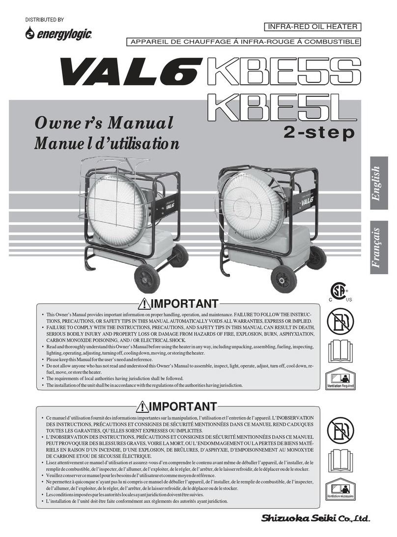
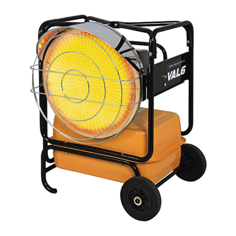
Val6 FIR-X5 User manual

2
3
3
4
4
5
6
14
15
7.
Troubleshooting ………………………………………….
Standard resistance & Voltage …………………………
Check & Repair …………………………………………
Names of Components …………………………………
Safety Devices ……………………………………………
Error Code ………………………………………………
Sequence Time Chart …………………………………….
Wiring Diagram ……………………………………………
Specifications …………………………………………….
6.
9.
8.
5.
ED2 2021.08
Contents
1.
2.
4.
3.
Maintenance Manual
1

【Names of Components】
1 Combustion chamber 16 Solenoid valve 30 Off-timer display lamp
2 Radiation tube 17 Solenoid valve 31 Down button
3 Guard 18 Flame monitor 32 Up button
4 Operation panel 19 Draft tube 33 Conbustion level lamp
5 Exhaust port 20 igniter 34 Mode switching button
6 Wheel 21 Control board 35 Thermo control mode lamp
7 Fuel tank 22 Fuel preheater 36 Auto control mode lamp
8 Fuel gauge 23 Fuse 37 Off-timer setting button
9 Fuel tank cap 24 Preheating lamp 38 Continuous Conbustion lamp
10 Burner cover (Burner inside) 25 Run lamp 39 1hour lamp
11 Tip-over switch 26 Low fuel lamp 40 2hours lamp
12 Fuel sensor 27 Display 41 4hours lamp
13
Overheat protection
(The backside of the
burner)
28 Display switching button 42 8hours lamp
14 External thermostat cord 29 Temperature display lamp 43 Operation switch
15 Combustion fan
1
2

2【Safety Devices】
3【Error Code】
Display Safety device Explanation
A1 Flame detection
When misfire occurs or flame goes out during the operation, the heater shuts
down automatically.
A2 Low fuel
No fuel in the fuel tank.
A3 Overheat
When overheating is detected, the heater shuts down automatically.
A4 Tip-over
When the heater receives a large vibration or shock, it shuts down
automatically.
A5 Abnormal fan speed
When an abnormality of the combustion fan is detected during combustion,
the heater shuts down automatically.
A6 Low voltage stop
When the supply voltage is about 70V or less, the heater shuts down
automatically.
A7 3 consecutive misfire
When there are 3 consecutive misfire, the operation is prohibited
automatically.
A8 Circuitboard communication abnomality
When communication between the control board and the operation board
fails, the operation is prohibited automatically.
HV High voltage
When the heater is connected to an abnormal high voltage, the operation is
prohibited automatically.
LV Low voltage detection
When the power supply volatage drops below appoximately 90volts during
operation, 「LV 」is displayed and the operation is continued.
※Refer to「7.Troubleshooting (P.6)」for countermeasure.
Safety Devices Detecting condition Working condition after detecting
Flame detection(Misfire) When the heater cannot detect a ignition during operation.
The error code「A1」is displayed and the fan cools down the heater for
about 5 minutes ( hereafter refferd to as Post-purge).
When the heater detects a out of fuel at the beginning
of operation.
The error code「A2」is displayed .
When it pasted 60 minutes after the heater detects
a out of fuel.
The error code「A2」is displayed and Post-purge sequence runs for 5
minutes.
Overheat protection
When the heater overheats.
The error code「A3」is displayed and if the heater is operating , Post-
purge sequence will run for 5 minutes.
Tip-over When the heater detects a vibration or an impacts.
The error code「A4」is displayed and if the heater is operating, Post-purge
sequence will run for 5 minutes.
Abnormal fan speed
When the heater detects an abnormal fan speed.
The error code 「A5」is displayed and if the heater is operating, Post-
purge sequence will run for 5 minutes.
High voltage
When the heater detects a high voltage(about 145V) at
the beginning of the operation.
The error code「HV」is displayed and the operation is prohibited.
Low voltage stop
When the heater detects a low voltage(about 70V) at the
during of the operation.
The error code「A6」is displayed and if the heater is operating, Post-purge
sequence will run for 5 minutes.
3 consecutive misfire When there are three consecutive misfire.
There error code「A7」is displayed and the heater runs for 5 minutes.After
that the operation is pohibited.
Circuitboard communication
abnomality
When a communication between the control board and the
operation board fails.
The error code 「A8」is displayed and if the heater is operating, Post-
purge sequence will run for 5 minutes.
Low voltage detection
When the heater detects low voltage (about 90V) during
the operation.
The error code「LV」is displayed and the operation is continued.
Power outage safety device
When the power supply is restored after it shuts down
during operation because of blackout or other reason.
The error code「--」is displayed and the operation is prohibited.
Low fuel
3

4【Sequence Time Chart】
5【Wiring Diagram】
CN12
CN9
CN11
CN10
CN13
CN5
CN6
CN8
CN7
CN4
CN1
CN3
CN2
CN17
Ignition
a: Ignition delay timer d: Post ignition
b: Pump delay timer e: Stable time
c: Solenoid valve delay timer
※Fuel pre-heater : When the power cord is connected, the heater preheats for 3 minutes if the outside temperature is
less than 41℉.
50sec
e
300sec
Post purge
Fuel pre-heater
15sec
a
2sec
b
5sec
c
10sec
d
Operation Switch
Fan Motor
Igniter
Fuel Pump
Solenoid Valve
Flame Monitor
PLUG
SWITCH
SWITCH
IN
ON
OFF
4

6【Specifications】
Specifications
Model Type VAL6 FIR-X5
Type Radiated / Direct-fired
Ignition System High intensity discharge
Fuel Kerosene or Fuel-Oil no heavier than No.2(Diesel)
Fuel Consumption
(Heat Output)
Level 5 : 0.53 GAL/h, 1.72 kg/h (75,100 BTU, 22.0 kW)
Level 4 : 0.50 GAL/h, 1.63 kg/h (71,300 BTU, 20.9 kW)
Level 3 : 0.48 GAL/h, 1.55 kg/h (67,600 BTU, 19.8 kW)
Level 2 : 0.45 GAL/h, 1.46 kg/h (63,800 BTU, 18.7 kW)
Level 1 : 0.42 GAL/h, 1.38 kg/h (60,100 BTU, 17.6 kW)
Tank Capacity 7.9 gallons(29.9L)
Continuous Operating Time Level 5 : 14 hours(Stopped by fuel sensor)
Dimensions (inch) 46.0 H x 59.6 W x 13.6 D
Weight (w/empty tank) 172 Lbs, 78kg
Power Supply AC 120V (60Hz)
Power Consumption
Igniting : 65W,
Burning : 45W(Lv.5), 41W(Lv.4), 37W(Lv.3), 34W(Lv.2), 31W(Lv.1)
+44W When Preheater is operating
Electric Fuse 3A 250V
Operating Noise Level 56 dBA(Lv.5), 55dBA(Lv.4), 54dBA(Lv.3), 53dBA(Lv.2), 52dBA(Lv.1)
Safety Systems
Tip-over Switch
Flame Monitor
Electrical System Protection
(High Voltage, Low Voltage,
Prevention of automatic ignition after black-out)
Overheat Protection
Anomaly detection system for fan motor
Other Systems
Preheater for fuel supply
Solenoid valve for remaining fuel
Valve for draining air
Functions
Combustion mode
Thermo control mode
( The combustion level is manually maintained. )
Auto control mode
( The combustion level is automatically adapted
to programed temperature setting )
OFF-timer ( 1, 2, 4, 8 hours )
Display(7seg) switching
( Temperature[F], OFF-timer remaining time )
5

【Troubleshooting】
Contents
Page
7
8
9
11
11
12
12
13
13
13
13
1
Fuel leaks
4
3
10
The heater does not start
The heater does not ignition
Smoke comes out
Fuse blows out
Smell of fuel comes out
8
7
Combustion is not stable
Misfire within 40 seconds after ignition
7
Display「LV」
Combustion stop during the operation
9
№
2
Phenomenon
5
11
6
Noise occurs
6

Result Cause Remedy
1
A. When the plug is put into an outlet.
0Ω Failure of transformer Replace transformer
0Ω
0Ω Failure of pre-heater Replace pre-heater
B. When the switch is turned on.
Failure of fan motor Replace fan motor
0Ω
C.
Failure of igniter Replace of igniter
D.
Failure of fuel pump Replace of fuel pump
0Ω
E. Failure of solenoid valve Replace of solenoid valve
0Ω
When fuse blows out about 17
seconds after turning on.
※When igniter is operated.
※When fuel pump is operated.
※When solenoid valve is operated.
Replace burner controller
Standard: white-white:about 110Ω ⇒ Figure 3
(P.17)
yellow-yellow:about 20Ω
Failure of burner controller
Replace burner controller
Unplug pre-heater connector, then measure coil
resistance values
Surge absorber is short-
curcuited.
Standard: black-black(Thick):
about 4kΩ ⇒ Figure 3
(P.17)
Unplug fan motor connector (CN 3) from burner
controller, then measure resistance values
Fuse does not blow out
Unplug solenoid valve connector (CN 6) from burner
controller, then measure resistance values
Unplug igniter connector(CN 4) from electrode、then
measure coil resistance values of the high voltage side
Fuse does not blow out
standard red-red:about 1.8kΩ ⇒ Figure 3(P.17)
Unplug fuel pump connector(CN 5) from burner
controller, then turn on
How to check
Unplug igniter connector(CN 4) from burner controller,
then turn on
0Ω
Fuse blows out.
Unplug fan motor connector (CN 3) from burner
controller, then turn on
※When fan moter is operated.
Standard: other than 0Ω ⇒ Figure 5 (P.18)
Standard: red-blue:about 520kΩ ⇒ Figure 3 (P.17)
Disconnect all connectors from the burner controller,
then plug the power cable into an outlet
red-red:about 3Ω
Fuse does not blow out
Unplug transformer connector (CN 2) from burner controller,
then measure coil resistance values
Phenomenon
When fuse blows out about 15
seconds after turning on.
Fuse blows out
Measure resistance at surge absorber (SA1)
When fuse blows out about 22
seconds after turning on.
Unplug solenoid valve connector(CN 6) from burner
controller, then turn on
Unplug fuel pump connector (CN 5) from burner
controller, then measure resistance values
standard: blue-blue:about 88Ω ⇒ Figure 3 (P.17)
Standard: white-blue:about 400Ω ⇒ Figure 3 (P.17)
7

Result Cause Remedy
How to check
Phenomenon
2
A. The lamp does not light on.
AC 0V No power source is supplied Operate with appropriate power source
Fuse blows out Replace fuse
Disconnection of power cable Replace power cord
AC 0V
AC 0V Failure of transformer Failure of transformer.
∞Ω Disconnection of transformer Replace transformer
Failure of operating switch Replace operation switch
Failure of burner controller Replace burner controller
B.
Power source is restored
after blackout when operating
Power cord is connected with
switching on
Failure of burner controller
Replace burner controller.
C. Refuel the fuel tank and operate the heater It works normally. No fuel in the fuel tank. Refuel
Failure of fuel sensor
Replace fuel sensor
Replace fuel sensor cord
Standard: black-black : Conducting (0Ω) with fuel
Failure of burner controller Replace burner controller
Display「A2」
Pour the fuel in the fuel tank about a one-third and,
unplug fuel sensor connector (CN10), and then check
conduction with multimeter
※When it does not correspond to the above content
If the multimeter reads ∞ Ω,
Disconnection of fuel sensor
cord
Disconnection of power cable
The heater does not start.
Disconnection of transformer
Failure of burner controller
Disconnection of operation
switch connector
Disconnection of operation
switch cord
※When power outage safety device
is operated
It works normally
(Lamps is lit)
standard: yellow-yellow:AC 16V
yellow-yellow:about 20Ω
Measure voltage at output side of transformer connector
Unplug transformer connector (CN 2) from burner
controller, then measure coil resistance values
Replace burner controller
It does not conduct when operation
switch is turned on(∞Ω)
It works normally.
( A ambient temperature is
displayed)
※When it does not correspond to the above content
Plug connector (CN17) firmly
Replace operation switch cord
standard: white-white:AC 120V ⇒ Figure4 (P.17)
Plug connector (CN1) firmly
-
Standard: red-red : Conducting (0Ω) when turned on
Plug connector (CN2) firmly
※When it does not correspond to the above content
It works normally
(Lamps is lit)
Replug power cable(CN1), and then turn on
Unplug operation switch connector (CN17), and then
check conduction with multimeter
red-red:about 3Ω
Replug operation switch connector (CN17) , and then
turn on
red-red:AC 12.5V ⇒ Figure4 (P.17)
Display「--」
Turn off the operating switch, and then turn on
Standard: white-white:about 110Ω ⇒ Figure3 (P.17)
Measure voltage at (CN1) terminal burner controller
standard: AC 120V ⇒ Figure 4 (P.17)
Replug in transformer connector (CN 2), and then turn
on
Measure voltage at input side of transformer connector
It works normally
(Lamps is lit)
8

Result Cause Remedy
How to check
Phenomenon
2
D. Display「A3」
Failure of overheat protection Replace overheat protection
Disconnection of overheat
protection cord.
Replace overheat protection cord
Lack of burner packing Add burner packing
Deterioration of burner packing
Replace burner packing
Failure of burner controller. Replace burner controller
E. Display「A4」
※Tip-over detector operation.
Failure of tip-over switch
cord
Replace tip-over switch cord
Failure of burner controller Replace burner controller
F. Display「A5」
Does not rotate or it move slowly Combustion fan is locked Cancel the lock or replace combustion fan
DC 170V Failure of combustion fan Replace combution fan
DC 0V Failure of burner controller Replace burner controlller
G. Display「A6」
Lower than AC70V Supplied voltage is too low Operate with appropriate power source
Failure of burner controller Replace burner controller
H. Display「HV」 Measure the voltage of AC outlet
More than AC 145V Supplied voltage is too high Operate with appropriate power source
Failure of burner controller. Replace burner controller
I. Display「A7」
Failure of burner controller. Replace burner controller
3
Display「A1」
A. Fuel pump does not operate at all. ∞Ω Failure of fuel pump.
※High voltage detection.
「A7」is not displayed
(A ambient temperature is displayed)
Disconnection of fuel pump
connector
「A3」is not displayed
(A ambient temperature is displayed)
Plug connector (CN11) firmly
Disconnection of overheat
protection connector.
Plug connector (CN3) firmly
Normal indication after 3
consecutive misfire
Plug connector (CN11) firmly
Replace tip-over switch
※When overheat protection is operated
Plug connector (CN5) firmly
Disconnection of fuel pump
connector
-
※Low voltage stop.
Standard: black-black : Conduction in horizontal(0Ω) ⇒
Figure3 (P.17)
※3 consecutive misfire.
※Combustion fan abnomality detection .
Plug connector (CN1) firmly
「A5」is not displayed
(A ambient temperature is displayed)
standard: AC 120V ⇒ Figure4 (P.17)
「A6」is not displayed
(A ambient temperature is displayed)
「A3」is not displayed
(A ambient temperature is displayed)
Replug in combustion fan connector (CN 3) and then
turn on
Replug in tip-over detector connector (CN 11), and
then turn on
standard: AC 120V ⇒ Figure 4 (P.17)
Unplug the fuel pump (CN 5) from burner controller,
then measure resistance values
Replug in power cable(CN1), and then turn on
Replug in the fuel pump connector (CN 5), and then
turn on
Measure the voltage of AC outlet
Turn off the operation switch, and then plug the power
cable again
※When it does not correspond to the above content
※When it does not correspond to the above content.
※When it does not correspond to the above content
Measure the voltage at CN3 terminal on burner controller
Unplug tip-over detector connector (CN 11),
and then check lead with multimeter
Confirmation of burner packing ⇒ Figure15 (P.23)
※When it does not correspond to the above content
「A1」is not displayed
(A ambient temperature is
displayed)
※When it does not correspond to the above content
Replug overheat protection connector (CN 11) , and
then turn on
The heater does not ignite.
Unplug overheat protection connector (CN 11), and
then check conduction with multimeter
The heater does not start.
Standard: red-red : Conduction(0Ω) ⇒ Figure3
(P.17)
Turn the combustion fan by hand
standard: DC 170V ⇒ Figure4 (P.17)
It does not conduct when operation
switch is turned on(∞Ω)
(Overheat protection is not
detected)
It does not conduct when operation
switch is turned on(∞Ω)
(Overheat protection is detected)
Disconnection of tip-over
connector
Failure of tip-over switch
Disconnection of combustion fan
connector.
Disconnection of power
source connector
It does not conduct in horizontal
Replace pump
standard: blue-blue:about 88Ω ⇒ Figure3 (P.17)
9

Result Cause Remedy
How to check
Phenomenon
Display「A1」 There is a hole
Stop of operation due to light
leakage detection
Replace combustion chamber
A. Fuel pump does not operate at all. Failure of flame monitor Replace flame monitor
Check if the pipe is clogged
Fuel line is clogged Flow rate is lower by clogged Clean fuel line
B.
Fuel pump works but no fuel supply or
Check if filter element is dirty ⇒ Figure7(P.19)
Filter element is dirty Filter element is clogged Replace filter element
low supply. Check looseness of each joints
The connection has become loose Air is coming Fasten joints more tightly
Check if the fuel pump is clogged
Pipe is clogged Flow rate is lower by clogged Replace pump
Nozzle is clogged Flow rate is lower by clogged Replace nozzle
About DC 110V(For reference) Failure of solenoid valve Replace solenoid valve
0V Failure of burner controller Replace burner controller
∞Ω Failure of solenoid valve Replace solenoid valve
C. Igniter does not spark.
Igniter does spark. Plug connector (CN4) firmly
AC 120V Failure of igniter Replace igniter
Disconnection of Igniter
connector
AC 0V Failure of burner controller Replace burner controller
∞Ω Failure of igniter. Replace igniter
D. Igniter does spark. Check the fuel ⇒ Figure 8(P.19) Use fuel other than diesel and kerosene Low quality fuel Operate with appropriate fuel
Be mixed with water
Diesel and kerosenel goes bad
Measure the alignment of electrode. Part is out of standard position. Replace electrode
Check air inlet opening of fan moter. Air inlet opening is unusual. Operate with appropriate air inlet opening
Measure voltage at the CN4 terminal burner controller
Alignment of electrode is out
of standard
Check if there is a hole in the combustion section part
Standard: ⇒ Figure10(P.20)
Check if the nozzle is clogged
Unplug the solenoid valve connector (CN 6) from the
burner controller, then measure the resistance values
standard: 3.0 ⇒ Figure 13 (P.22)
standard: red-red:1.8kΩ ⇒ Figure3 (P.17)
Unplug the igniter connector(CN 4) from the
electrode、then measure the coil resistance values
Replug in igniter connector (CN 4), and then turn on
Voltage of flame monitor
The valves does not change or it is
much different from the standard
standard: dark:DC 5V or higher ⇒ Figure4 (P.17)
Measure voltage at CN6 terminal on burner controller
standard: black-black:about DC110V ⇒ Figure4 (P.17)
light:DC 5V or lower
Standard: black-black(Thick):about 4kΩ ⇒ Figure3(P.17)
standard: AC 120V ⇒ Figure4(P.17)
Replug in solenoid valve connector(CN 6) , and then
turn on
Improper quantity of
combustion air
「A1」is not displayed
(A ambient temperature is displayed)
Disconnection of solenoid
valve connector
Plug connector (CN6) firmly
Disconnection of Igniter
connector.
10

Result Cause Remedy
How to check
Phenomenon
4
lens of flame monitor is dirty
Lock of light quantity to flame
monitor
Clean flame monitor lens
Plug connector (CN 9) firmly
Display「A1」
The value is higher than DC 5V Failure of burner controller Replace burner controller
Nozzle is clogged Flow rate is lower by clogged Replace nozzle
Make sure that the filter element is dirty ⇒ Figure7(P.19)
Filter element is dirty Filter element is clogged Replace filter element
Check air inlet opening of fan moter Air inlet opening is unusual Operate with appropriate air inlet opening
Failure of burner controller. Replace burner controller
5 Combustion stop during the operation. Check the fuel ⇒ Figure 8(P.19)
Use fuel except diesel and kerosene
Low quality fuel Operate with appropriate fuel
A. Display「A1」 Be mixed with water
Diesel and kerosenel goes bad
Check air inlet opening of fan moter Air inlet opening is unusual. Operate with appropriate air inlet opening
lens of flame monitor is dirty.
Lock of light quantity to flame
monitor Clean flame monitor lens
Check looseness of each joints
The connection has become loose. Air is coming Fasten joints more tightly
B. Refuel and operate the heater It works normally. No fuel in the fuel tank. Refuel
Failure of fuel sensor
Replace fuel sensor
Replace fuel sensor cord
Standard: black-black : Conducting (0Ω) with fuel
Failure of burner controller Replace burner controller
C. Display「A3」 Check the ambient temperature Operate in lower than 30℃(86°F)
Failure of overheat protection Replace overheat protection
Disconnection of overheat
protection cord.
Replace overheat protection cord
Lack of burner packing Add burner packing
Deterioration of burner packing
Replace burner packing
D. Failure of tip-over detector Replace tip-over switch
※Tip-over detector operation
Disconnection of tip-over
detector connector
Replace tip-over switch cord
Disconnection of tip-over connector Plug connector (CN11) firmly
Ambient temperature is too
high
Failure of flame monitor
※ Ignition not detected during
operation
It does not conduct when operation
switch is turned on(∞Ω)
(Overheat protection is detected)
Confirmation of burner packing ⇒ Figure15 (P.23)
Display「A4」
Plug connector (CN11) firmly
It does not conduct in horizontal(∞
Ω)
「A3」is not displayed
(A ambient temperature is displayed)
Replace flame monitor
Check if the nozzle is clogged
Improper quantity of
combustion air
Improper quantity of
combustion air
※When it does not correspond to the above content
standard: 3.0 ⇒ Figure 13 (P.22)
light:DC 5V or lower
standard: 3.0 ⇒ Figure 13 (P.22)
The valves does not change or it is
much different from the standard.
standard: dark:DC 5V or higher ⇒ Figure4(P.17)
Replug overheat protection connector (CN 11) , and
then turn on
※Overheat protector operation.
※Ignition not detected during
operation.
Replug tip-over detector connector (CN 11), and then
check conduction with multimeter
Standard: black-black : Conduction(0Ω) when turned
on.
「A1」is not displayed
(A ambient temperature is displayed)
Disconnection of flame
monitor connector
Unplug overheat protection connector (CN 11), and
then check conduction with multimeter
It does not conduct when operation
switch is turned on(∞Ω)
(Overheat protection is not detected)
Misfire within 40 seconds after
ignition.
Standard: red-red : Conduction(0Ω) ⇒ Figure3
(P.17)
Check dirty of flame monitor lens ⇒ Figure11(P.21)
Display「A2」
※When it does not correspond to the above content
Check voltage of flame monitor
Replug in the flame monitor connector (CN 9) , and
then turn on
Standard: Lower than 30℃(86゜F)
Pour the fuel in the fuel tank about a one-third and,
unplug fuel sensor connector (CN10), and then check
conduction with multimeter
Disconnection of operation
fuel sensor cord
More than 30℃(86°F)
If the multimeter reads ∞ Ω,
Disconnection of overheat
protection connector.
11

Result Cause Remedy
How to check
Phenomenon
6 Smell of fuel comes out. Check air inlet opening of fan moter Air inlet opening is unusual Operate with appropriate air inlet opening
Check if the pipe is clogged
Fuel line is clogged Flow rate is lower by clogged Clean fuel line
Check if filter element is dirty ⇒ Figure7(P.19)
Filter element is dirty Filter element is clogged Replace filter element
Check looseness of each joints
The connection has become loose Air is coming Fasten joints more tightly
Nozzle is clogged Flow rate is lower by clogged Replace nozzle
Marking is incorrect Incorrect nozzle. Use correct nozzle
Check the fuel ⇒ Figure 8(P.19)
Use fuel except diesel and kerosene
Low quality fuel Operate with appropriate fuel
Be mixed with water
Diesel and kerosenel goes bad
7 Smoke comes out. Check air inlet opening of fan moter. Air inlet opening is unusual. Operate with appropriate air inlet opening
Fan is dusty. Supplied air is reduced Clean combustion fan
Less than standard Operate with appropriate power source
Marking is incorrect. Incorrect nozzle. Use correct nozzle
An oxygen concentration is
low
Check the fuel ⇒ Figure 8(P.19) Use fuel except diesel and kerosene Low quality fuel Operate with appropriate fuel
Be mixed with water
Diesel and kerosenel goes bad
8 Fuel leaks Check looseness of each joints
The connection has become loose Air is coming Fasten joints more tightly
Be damaged and cracked Failure of drain packing Replace drain packing
9Display「LV」
Less than AC 90V Supplied voltage is low Operate with appropriate power source
Low voltage detection.
(continue ignition)
Failure of burner controller Replace burner controller
Extend combustion air inlet opening
standard : 3
Check the altitude where heater is used
It is being used at higher than the
altitude of 1000m(3000ft)
※When it does not correspond to the above content
The rotation number of
combustion fan is reduced
Check if the nozzle is clogged
Improper quantity of
combustion air
Check the dust of combustion fan
Check the power supply voltage
standard:AC 108~132V ⇒ Figure7 (P.19)
standard: 3.0 ⇒ Figure 13 (P.22)
Check the marking of the nozzle
mark: 0.40 G 80゜AJ (DELAVAN)
Check the condition of each part of drain packing
Check the power supply voltage
standard:AC 108~132V
standard: 3.0 ⇒ Figure 13 (P.22)
mark: 0.40 G 80゜AJ (DELAVAN)
Improper quantity of
combustion air
12

Result Cause Remedy
How to check
Phenomenon
10 Check air inlet opening of fan moter. Air inlet opening is unusual Operate with appropriate air inlet opening
Marking is incorrect Incorrect nozzle. Use correct nozzle
Check the fuel ⇒ Figure 8(P.19) Use fuel except diesel and kerosene Low quality fuel Operate with appropriate fuel
Be mixed with water
Diesel and kerosenel goes bad
11 Combustion is not stable. Check looseness of each joints
The connection has become loose Air is coming Fasten joints more tightly
An oxygen concentration is
low
Improper quantity of
combustion air
Check the altitude where heater is used
It is being used at higher than the
altitude of 1000m(3000ft)
Extend combustion air inlet opening
standard : 3
Noise occurs.
Noise occurs.
mark: 0.40 G 80゜AJ (DELAVAN)
standard: 3.0 ⇒ Figure 13 (P.22)
Check the marking of the nozzle
13

【Standard resistance & Voltage】
<Standard resistance of functional parts>
Connector No
Lead Condition Resistance Memo
On 0Ω
Off ∞Ω
not in working 0Ω
in working ∞Ω
not in working 0Ω
in working ∞Ω
CN4 1-2PIN black-Black(Thick) Output(Electrode side) about 4kΩ
CN5 1-3PIN Blue-Blue --- about 88Ω
CN6 2-4PIN Red-Red --- about 1.8kΩ
Disconnection ∞Ω
20℃ 13.0kΩ
Short 0Ω
CN8 1-3PIN WhiteーBlue --- 400Ω
4-8PIN White-White Input side 110Ω
CN2 1-2PIN Red-Red Output1 3Ω
5-6PIN Yellow-Yellow Output2 20Ω
enough fuel 0Ω
out of fuel ∞Ω
<Input &Output of each component>
Connector No
Lead Condition Voltage Memo
CN1 Black-White - AC 120V
CN4 Black-Black Input side AC 120V
CN3 Red-Blue -DC 170V
CN5 Blue-Blue - about DC 50V
4-8PIN White-White Input side AC120V
CN2 1-2PIN
Red-Red Output1 about 12.5V
5-6PIN Yellow-Yellow Output2 about 16V
CN6 2-4PIN Blue-Blue -about DC110V
CN8 1-3PIN WhiteーBlue - AC120V
68±9゜F → OFF
41±9゜F → ON
8
Operating Switch
CN17
1-2PIN
Red-Red
Power Cable
Parts
Black-Black
Transformer
Fuel pre-heater
Tip-over Switch
CN11
1-2PIN
Red-Red
Solenoid valve
---
about 520kΩ
Overheat Protection
CN11
3-4PIN
CN3
Red-Blue
Igniter
Solenoid valve
Fuel pre-heater
Temperature sensor
CN12
1-3PIN
Black-Black
Fan Motor
Black-Black
Fuel sensor
Igniter
Parts
Fuel Pump
Transformer
Normal scale :3.0
Fan Motor
CN10
1-2PIN
Fuel Pump
14

【Check & Repair】
Removing a burner cover
Removing a burner unit
Mesuring resistance
Mesuring voltage
Checking a surge absorber (SA1)
Replacing a fuse
Checking a filter element
Checking a fuel tank
Checking a fuel pump
Positioning a electrode
Cleaning a flame monitor
Checking a burner cone ・Whirl vane ・Stabilizer
Adjusting an air inlet opening of fan motor
Overheat protection system
Burner packing
P.19
P.19
P.20
P.20
P.21
P.21
P.16
P.16
P.17
P.17
P.18
P.18
Figure12
Figure13
Figure14
Figure15
P.22
P.22
P.23
Figure5
Figure6
Figure7
Figure8
Figure9
Figure10
Figure11
Figure1
Figure2
Figure3
Figure4
9
15

Removing a burner cover
Loosen five screws and take the burner cover off.
Removing a burner unit
サーモモードランプ
①
Figure2
Disconnect the 4 connectors from the burner controller.
参考資料(機能部品の基準抵抗)・・・・・・・
点検・修理方法図・・・・・・・・・・・・・・
(① Overheat prevention & Tip-over switch, ② Fuel sensor, ③ Operation board
connector, ④Temperature sensor : refer to Wiring diagram(P.4)
Figure1
仕様・・・・・・・・・・・・・・・・・・・・
修理マニュアル・・・・・・・・・・・・・・・
Screw
Burner cover
1
2
3
4
16

②
Mesuring resistance Mesuring voltage
①①
②
③
④
※
※
Measurement value refer to 「Standard resistance & Voltage」.(P.14)
※
Be careful not to insert the lead head of resistor strongly since damage in
connector may occur.
②
Figure4
Figure3
Remove the flare nut, high nut, hose, external thermostast cord and power code.
Make sure the power cord is disconnected.
Make sure the power cord isdisconnected.(when measuring resistance)
Operate the heater.
Turn on the multimeter and set AC
voltage range (partially direct current
range).
③
Insert the lead head of multimeter to
connector and measure voltage.
Unplug an intended connector from
burner controller.
Insert the lead head of multimeter to
connector [lead wire side] and
measure resistance.
Turn on the multimeter and set
multimeter range.
CAUTION
17

Checking a surge absorber (SA1)
Replacing a fuse
1.Loosen five screws of burner cover and then take the cover cover off.
2.Take out the fuse from the fuse holder.
3.Replace with a new one.
4.Close the fuse holder.
5.Put the burner cover back and then tighten screws.
Figure6
Figure5
Take out the operation board, and then point the lead head at solder part of SA1
SA1
Fuse holder
Fuse
18

Checking a filter element
1. Remove the suction pipe from the fuel tank.
2. If the filter is dirty, replace it with a new one.
3. Return the suction pipe to the fuel and firmly secure.
Checking a fuel tank
⑦
Figure7
Figure8
③
④
⑤
remaining in the fueltank, place the container under
①
②
Remove the fuel cap and insert a suctionpump into
the tank.
Remove as much fuel as possible (with the suction
pump). Be sure that the fuel being removed is put
the fuel tank).
and tilt the fuel tank until the fuel is completely
drained out of the tank. (At the same time, be
careful not to lose the drain bolt packing.)
only into a can or other container approved in your
Next, use a 24mm wrench to remove the drain bolt
Tighten the fuel cap firmly.
the drain bolt (of the fueltank).
(1.1gallons)capacity: to hold kerosene and water
and Fuel-Oil no heavier than No.2 (Diesel).
area for holding flammable liquids such as kerosene
Prepare an empty container of about 4 liters
⑥
Restore the drain bolt packing and tighten the
6drain bolt firmly so that fuel can not leak out (of
Wipe off kerosene or water spilled over the tank
and the surrounding area.
19

Checking a fuel pump
Take out a fuel outlet line then check whether or not fuel comes out.
Please be careful because the fuel strongly comes out.
Positioning a electrode
・Take out a burner and check each clearance as below.
Figure9
Figure10
Fuel outlet
9.6±0.5 mm
3.8±0.2 inch
2.3±0.2 inch
5.9±0.5 mm
20
Table of contents
Other Val6 Heater manuals
Popular Heater manuals by other brands

Everdure
Everdure HCT2075D Operation, maintenance and safety instructions

Salton elite
Salton elite SFH16E Instructions and warranty

Fanelite
Fanelite X01A USER MANUAL, INSTALLING AND OPERATING MANUAL

Sentiotec
Sentiotec Concept R Instructions for installation and use

Dimplex
Dimplex XLS24N installation instructions

Generac Mobile
Generac Mobile MFH500 owner's manual

Klarstein
Klarstein WONDERWALL 45 manual

Siemens
Siemens DE 1113415 Installation and operating instructions

Frost Fighter
Frost Fighter IDF500HS Installation - Operation/Maintenance Instructions and Parts List

Nesco
Nesco Spa Pro SP-08 user manual

EQUATION
EQUATION BH-1701T Assembly, Use, Maintenance Manual

OYPLA Home
OYPLA Home 3940 user manual